1
Heritage Series ADSL Bridge/ Router
Heritage Series
Multi-Mode
xDSL Router
User’s Manual
Dec. 2003
Heritage Series ADSL Bridge/ Router
Copyright
All rights reserved. No part of this document may be reproduced in any
form or by any means without written permission from the product
manufacturer.
Changes are periodically made to the information in this document. They
will be incorporated in subsequent editions. The product manufacturer
may make improvements and/or changes in the product described in this
document at any time.
Heritage Series ADSL Bridge/ Router
Table of Contents
Chapter 1 Introduction
1.1 Overview
1.2 Features and Compatibility
1.3 What’s in the package?
1.4 Important Rules for Safe Operation
1.5 Front Panel
1.6 Real Panel
1-1
1-1
1-2
1-4
1-5
1-8
1-9
Chapter 2 Installing and Configuring your xDSL
Router
2-1
2.1 Preparation for Hardware and Software Installation
2.2 Hardware Installation
2.3 Windows 95/98 setting for Ethernet LAN connection
2.3.1 Check TCP/IP protocol
2.3.2 TCP/IP installation
2.3.3 TCP/IP setting
2.4 Configuring the Router
2.4.1 Using TELNET via Ethernet interface
2.4.2 Using terminal program via serial console port
Chapter 3
Basic Configurations
3.1 Factory default configuration
3.2 Bridged RFC1483
3.3 Routed RFC1483
3.4 Classical IP (RFC1577)
3.5 PPP Over ATM (RFC2364)
3.6 PPP Over Ethernet (RFC2516)
Chapter 4
2-2
2-4
2-5
2-5
2-7
2-9
2-12
2-12
2-13
3-1
3-2
3-3
3-5
3-7
3-9
3-13
Advanced Configurations
4-1
4.1 Add NAT to Classic IP, PPP over ATM and PPP over
Ethernet
4-2
4.2 Enables NAT to RFC1483, Classic IP (RFC1577), PPP over
ATM (RFC2364) and PPP over Ethernet (RFC2516) in
Routing mode
4-4
4.3 Changing DHCP server configuration
4-6
4.4 Changing DHCP client configuration
4-9
4.5 PPTP Tunneling Configuration
4-11
Chapter 5
Managing The xDSL Router
5.1 Booting the xDSL Router from Ethernet
Network
5.2 Upgrading on-board flash memory from Ethernet
Network
5.3 SNMP
Chapter 6
xDSL Link Performance Statistics
Chapter 7 Command Sets for Command Line
Interface
Command Line Interface Conventions
Basic system command sets
Commands for ISFS and FLASHFS process
Commands for Bridge process
Commands for DHCP server process
Commands for DHCP client process
Commands for IP process
Commands for NAT process
Commands for PPP process
Commands for SNMP process
Commands for DSL process
Chapter 8
DHCP Server Operation
8.1 DHCP Server Overview
8.2 DHCP Server Configuration
8.3 Informal configuration guide
5-1
5-1
5-2
5-3
6-1
7-1
7-1
7-2
7-5
7-7
7-16
7-18
7-20
7-38
7-42
7-52
7-54
8-1
8-1
8-2
8-2
Heritage Series ADSL Bridge/ Router
8.4 Configuration reference guide
Chapter 9
DHCP Client Configuration
9.1 Protocol Timing
9.2 Lease requirements and requests
9.3 Other declarations
9.4 DHCP Options
Appendix A Product Specifications
Appendix B Troubleshooting
Appendix C Glossary
Appendix D Government Compliance Notices
8-4
9-1
9-2
9-3
9-4
9-5
A-1
A-4
A-8
A-16
Heritage Series ADSL Bridge/ Router
Chapter 1
Introduction
1-1
Introduction
1.1 Overview
This xDSL Router features two broadband technologies such as ADSL and
SHDSL. Multi-mode ADSL technology that provides a downstream rate of
up to 8Mbps over existing copper wire lines, which is more than 100 times
faster than a traditional 56K analog modem.
SHDSL technology that provides a symmetric upstream and downstream
rate of up to 2.3Mbps over existing copper wire lines.
And it can be connected to your PC or LAN through the 10Base-T or
100Base-T Ethernet interface.
This xDSL Router is designed to meet both the needs of single user, and
multiple users at small office and home office who want fast Internet access.
A wide variety of features and interoperability offer scalability and
flexibility for all the applications
1-2
Introduction
1.2 Features and Compatibility
This Heritage series Router provides the following features:
!
!
!
!
!
!
!
!
!
!
!
!
!
!
!
!
!
!
Multi-mode ADSL technology supports ITU-T G.dmt, G.lite, G.hs
and ANSI T1.413 issue 2 to provide interoperability with most of
DSLAM equipments.
SHDSL technology supports ITU-T G.shdsl, G.hs and ANSI
T1E1.4 to provide interoperability with most of DSLAM
equipments.
ATM (Asynchronous Transfer Mode) protocol allows the
QoS(Quality of Service) transmission over a network
Support for text-based and Windows-GUI based console
management over Telnet and serial connection
Support for remote configuration by your network administrator
via IP network.
Support IEEE 802.1d transparent bridging with spanning tree
algorithm.
Bridge filtering allows a network administrator to control the
flow of packets across the router
NAT : let multiple users on the LAN share one Internet
connection simultaneously
SNMP agent: allows monitoring and configuration by a standard
SNMP manager.
BOOTP/TFTP enable the remote configuration
DHCP client : let an ISP dynamically issue an address upon initial
connection.
DHCP server : automatically assigns IP addresses to all computer
on the LAN.
DNS relay : allows for automatic name resolution when no DNS
information is configured by the user.
PPTP tunneling enable VPN configuration.
Point-to-Point Protocol (PPP)
RFC 1483 Link Protocol
Password Authentication Protocol (PAP) and Challenge
Handshake Authentication Protocol (CHAP) security under PPP
protocol
IP routing support includes the RIP(Routing Information Protocol)
which allows the exchange of routing information on a TCP/IP
Heritage Series ADSL Bridge/ Router
!
!
Introduction
1-3
network
Flash memory for Software upgrade
Status LEDs for easy monitoring and troubleshooting
Some models of xDSL Router provides more features:
! Including 4-port 10/100 Base-T Ethernet Stackable Switch Hub.
1-4
Introduction
1.3 What’s in the package?
!
!
!
!
!
!
One xDSL Router
One 9VDC or 12VDC Adaptor, depend on different model
One RJ-11 Telephone Cable
One 10Base-T Ethernet straight-through Cable
One 9-pin to 9-pin RS-232 Cable (option)
One User’s Guide
All packages have been checked carefully for their completeness and
functionality before shipped. Please contact the place of purchase if any of
the above listed items are missing or damaged.
If you encountered any difficulty in using this product while all the above
items are complete, please refer to Appendix C for Troubleshooting
information before making the decision to return your xDSL Router to your
dealer.
Heritage Series ADSL Bridge/ Router
Introduction
1-5
1.4 Important Rules for Safe Operation
In addition to the careful attention devoted to quality standards on the
manufacture of your ADSL Router, safety is a major factor in the design of
every product. However, safety is your responsibility, too. This section lists
important information that will help assure your enjoyment and proper use
of the ADSL Router and accessory equipment. Please read them carefully
before operation and using your Router.
! Read and Follow Instructions – you should read all the safety and
operating instructions before operating the Router.
! Retain Instructions – You should save all the safety and operating
instructions, for your future reference.
! Heed Warning – Comply with all warnings on the products and in
the operating instructions.
! Check Power Sources – Operate this product only from the type of
power source indicated on the product’s marking label. If you
are not sure of the type of power supplied to your home, consult
your dealer or local power company.
! Be Careful of Overloading – Do not overload wall outlets or
extension cords, as this can result in a risk of fire or electric shock.
Overloaded AC outlets, extension cords, frayed power cords,
damaged or cracked wire insulation, and broken plugs are
dangerous. They may result in a shock or fire hazard.
Periodically examine the cord, and if its appearance indicates
damage or deteriorated insulation, have it replaced by your
service technician.
! Protect Power Cords – Route power supply cords so that they are
not likely to be walked on or pinched by items placed upon or
against them. Pay particular attention to cords where they are
attached to plugs and convenience receptacles, and examine the
point where they exit from the product.
! Check Ventilation – Slots and openings in the enclosure are
provided for ventilation to ensure reliable operation of the
product and to protect it from overheating. Do not block or cover
these openings. Never block these openings by placing the
product on a bed, sofa, rug, or other similar surface. Never place
this product near or over a radiator or heat register, or any other
1-6
!
!
!
!
!
!
!
!
!
!
!
!
Introduction
heat source (including amplifiers). Do not place this product in a
built-in installation, such as a bookcase or equipment rack, unless
you provide proper ventilation.
Do Not Use Accessories – Do not use attachments, unless they are
recommended by your vendor, as they may cause electrical or
fire hazards.
Use the Recommended Power Adaptor – You must use the Power
Adaptor that comes with your ADSL Router.
Do Not Use Near Water – Do not use this product near water. For
example, near a swimming pool, bath tub, wash bowl, and the
like.
Do Not place Near High Temperature Source – For example near
a steamer, kitchen range fire, and the like.
Use Caution in Mounting This Product – Do not place this
product on an unstable surface or support. The product may fall,
causing serious injury to a child or adult, as well as serious
damage to the product.
Use Care in Moving Product-and-Cart Combinations – Quick
stops, excessive, force and uneven surfaces may cause the
product-and-cart combination to overturn.
Unplug Power Before Cleaning – Do not use liquid cleaner or
aerosol cleaner. Use a damp cloth for cleaning.
Keep Objects Out of Openings – Never push objects of any kind
into this product through openings, as they may touch
dangerous voltage or “short-out” parts, which could result in a
fire or electric shock. Never spill liquid on the product.
Protect From Lightning – For added protection for this product
during a lightning storm, or when it is left unattended and
unused for long periods of time, unplug it from the wall outlet,
and disconnect the cable system. This will prevent damage to the
product due to lightning and power line surges.
Turn Off the Power Switch Between DC Plug Off and On.
Do Not Remove Covers – Do not attempt to service this product
yourself, as opening or removing covers may expose you to
dangerous voltage or other hazards.
Unplug this Product From Wall Outlet Carefully, as the Power
Adaptor May Be Hot.
Heritage Series ADSL Bridge/ Router
Introduction
1-7
! Refer Servicing to Qualified Service Personnel Under the
Conditions Listed Below.
# When the power supply cord or plug is damaged.
# If liquid has been spilled or objects have fallen into the
product.
# If the product has been exposed to rain or water.
# If the product does not operate normally by following the
operating instructions. Adjust only those controls that are
covered by the operating instructions.
# If the product has been dropped or the cabinet has been
damaged.
# When the product exhibits a distinct change in
performance, such as the inability to perform basic
functions – this indicates a need for service.
! Require Safety Check – Upon completion of any service or repairs
to this product, ask the service technician to perform safety
checks recommended by service point to determine that the
products is in safe operating condition.
Introduction
1-8
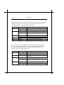
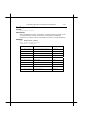
1.5 Front Panel
The xDSL Router has five status LEDs for diagnostics. You can monitor the
LEDs during operation. Following table shows the xDSL Router status
LEDs and identifies what each LED light means.
Function
POWER
xDSL
PC
RX
TX
Behavior
Dark
Light
Flashing slowly
Light
Dark
Light
Flashing
Flashing
Definition
Power off
Power on
xDSL training in progress
xDSL link is establish and ready to
transfer data
Ethernet link absent or power off
Ethernet link present
Receiving data from xDSL link
Transmitting data to xDSL link
The xDSL Router which including 4-port stackable switch hub that has
several status LEDs for diagnostics. You can monitor the LEDs during
operation. Following table shows the xDSL Router status LEDs and
identifies what each LED light means.
Function
POWER
TX/RX
Behavior
Dark
Light
Flashing
LINK
Flashing slowly
Light
L1 ~ L4
Dark
Light
Definition
Power off
Power on
Transmitting/Receiving data to/from
xDSL link
xDSL training in progress
xDSL link is establish and ready to
transfer data
Ethernet link absent or power off
Ethernet link present
Heritage Series ADSL Bridge/ Router
Introduction
1-9
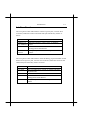
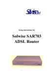
1.6 Rear Panel
The rear panel of the xDSL Router consist of power jack, Console Port
connector, Ethernet connect and xDSL link jack which they means as
below:
Function
xDSL
10Base-T or
10/100Base-T
Console
DC 9V or
DC12V
Definition
xDSL jack connect to DSL line from TelCo.
Ethernet interface connect to PC or HUB for
LAN.
This is RS232C interface and use to
management xDSL Router.
The power jack connects to Adaptor from wall
outlet.
The rear panel of the xDSL Router which including 4-port stackable switch
hub consist of power jack, Console Port connector, Ethernet connects and
xDSL link jack which they means as below:
Function
xDSL
Up-Link
L1 ~ L4
Console
DC 9V
Definition
xDSL jack connect to xDSL line from TelCo.
This is HUB feature cascade to another HUB for
expand LAN.
Ethernet Ports: Port1 to Port4
This is RS232C interface and use to
management xDSL Router.
The power jack connects to Adaptor from wall
outlet.
1-10
Introduction
Heritage Series ADSL Bridge/ Router
Installing and Configuring your xDSL Router
Chapter 2
2-1
Installing and
Configuring your xDSL
Router
The major functions of the xDSL Router are performed by using Ethernet
10Base-T or 10/100Base-T network interface. Your computer has to install
an Ethernet NIC card and set up the TCP/IP protocol before start to using
the xDSL Router.
The xDSL Router also provides a serial console port for monitoring and
configuring the Router via the xDSL Configuration Tool or HyperTerminal
program.
2-2
Installing and Configuring your xDSL Router
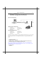
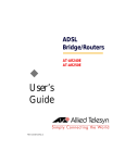
2.1 Preparation for Hardware and software
installation
Before start the hardware installation. Please prepare all the materials listed
below regarding to your application.
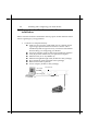
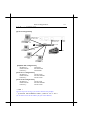
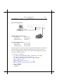
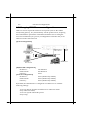
1.
Connect to a computer directly
! xDSL service provider or ISP/NSP service contract. Please
sign an appropriate Internet connection contract with a
reliable ISP/NSP and get necessary connection information
that will help you configuring your Router.
! Personal computer with OS that support Ethernet interface
! TCP/IP protocol installed in your personal computer
! Ethernet card (10 or 10/100Base-T)
! Ethernet straight-through cable (included in this package)
! RJ-11 telephone cable (included in this package)
! RS-232 serial cable (optional)
! Power adaptor (include in this package)
Serial Port
Console Port
Ethernet Port
Ethernet Port
DSLAM/ISP
Heritage Series ADSL Bridge/ Router
Installing and Configuring your xDSL Router
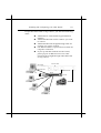
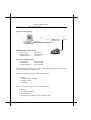
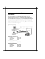
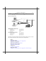
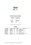
2.
2-3
Connect to more than one computer
Excepts the items listed on step 1 above, you still need following
items:
! Additional PC with OS that support Ethernet
interface.
! Additional Ethernet card for each PC you want
to connect
! Additional Ethernet Straight-through cable for
each PC you want to connect.
! One Ethernet Hub is required for more than one
computer connection.
! If your up-link hub without cascade switch,
please prepare an Ethernet crossover cable
instead of the straight-through cable that listed
on step 1 above.
Console Port
Serial Port
Ethernet Port
Ethernet Port
HUB
PC A
Up-Link
PC B
DSLAM/ISP
PC C
PC N
2-4
Installing and Configuring your xDSL Router
2.2 Hardware Installation
Before start to configure your Router, you have to complete all the
hardware installation. The following steps provide instructions for
installing your Router.
1.
2.
3.
4.
5.
6.
Be sure the power switch on the right side of the Router is at the
OFF status.
Connect the power adaptor to the power jack that marked Power
at the rear panel of the Router, then plug in the DC power
adaptor to the wall electrical outlet.
Connect the Ethernet cable.
A) If connect to computer directly
Connect one end of Ethernet straight-through cable to the
Ethernet port on your computer, then connect the other
end of Ethernet straight-though cable to the connector that
marked 10/100Base-T at the rear panel of the Router.
B) If connect to more than one computer via Hub Connect one
end of Ethernet straight-through cable (If your up-link hub
without cascade switch, please use an Ethernet crossover
cable instead) to the uplink port on the Ethernet Hub, then
connect the other end of Ethernet cable to the connector that
marked 10/100Base-T at the rear panel of the Router.
Connect one end of RJ11 telephone cable to the xDSL line jack
that marked xDSL at the rear panel of the Router, then connect
the other end of RJ-11 telephone cable to the xDSL service port
that your xDSL service provider or ISP installed.
Connect the male (9 pin) end of the RS-232 serial cable to the
connector that marked Console port at the rear panel of the
Router, then plug the other end of the RS-232 serial cable to the
RS-232 serial port of your computer.
Turn on the power switch. The Router should perform a self-test,
and then be ready for use.
Heritage Series ADSL Bridge/ Router
Installing and Configuring your xDSL Router
2-5
2.3 Windows 95/98 setting for Ethernet LAN
connection
Either connect to Internet or configure the Router via Ethernet, the TCP/IP
protocol is really necessary. And your computer must be on the same
subnet with the Router.
When you directly connect the Router to your computer through the
Ethernet network, you will first configure your computer to obtain an IP
address automatically from your Router’s DHCP server, or specify an IP
address and Subnet Mask to the same subnet as remote host. The
following steps provides the instructions to setup your computer to obtain
an IP address by using Windows 95/98 on a PC
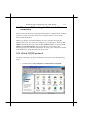
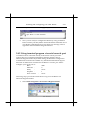
2.3.1 Check TCP/IP protocol
To check if TCP/IP is properly installed, please proceed to the following
steps.
1.
Double-click on My computer->Control Panel->Network
2-6
2.
3.
4.
Installing and Configuring your xDSL Router
In Network window, check if TCP/IP is shown and properly
setup for the Ethernet card that installed in your computer (for
example, TCP/IP->Realtek RTL8029(AS) PCI Ethernet NIC).
When TCP/IP has properly installed, please proceed to 2.3.3
TCP/IP Setting
When TCP/IP has not properly installed, go to next section to
install the TCP/IP protocol.
Heritage Series ADSL Bridge/ Router
Installing and Configuring your xDSL Router
2-7
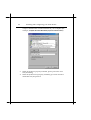
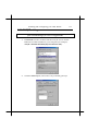
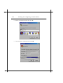
2.3.2 TCP/IP installation
Attention: When install TCP/IP protocol, you need Windows CD-ROM
1.
2.
In Network window, click the Add button.
Choose the Protocol and click Add.
3.
In Select Network Protocol window, choose Microsoft in
Manufacturers and TCP/IP in Network Protocols. Then click OK
2-8
4.
Installing and Configuring your xDSL Router
Confirm if the TCP/IP protocol has been correctly setup with
your Ethernet card.
Heritage Series ADSL Bridge/ Router
Installing and Configuring your xDSL Router
2-9
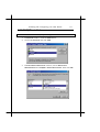
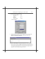
2.3.3 TCP/IP setting
Attention: When connecting your xDSL Router with existing LAN, consult
your network manager for correct configurations
1.
In Network window, double-click the TCP/IP service for the
Ethernet card that installed in your computer (for example,
TCP/IP > Realtek RTL8029(AS) PCI Ethernet NIC).
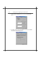
2.
Click the Gateway tab, and remove any installed gateways.
2-10
Installing and Configuring your xDSL Router
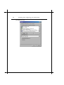
3.
Click the DNS configuration tab, and click the disable DNS
button.
4.
For DHCP client, Click the IP address tab, and click the Obtain
an IP address automatically button.
Heritage Series ADSL Bridge/ Router
Installing and Configuring your xDSL Router
5.
6.
7.
2-11
For Fixed IP or DHCP server, Click the IP address tab, and click
the Specify an IP address button. Then set IP Address and
Subnet Mask to the same subnet as remote host. Refer to Chapter
3.2 for example.
Click OK to save the new setting.
Click Yes when prompted for “Do you want to restart your
computer ?”. Your computer will restart to make the new setting
in effects.
Now your computer is ready to access your Router via Ethernet
network.
2-12
Installing and Configuring your xDSL Router
2.4 Configuring the Router
There is some setup required to get your xDSL Router working properly.
The configuration of the xDSL Router can be accessed in three ways:
# Using TELNET via Ethernet interface
# Using terminal program via serial console port
# Using xDSL Configuration Tool (ACT) via serial console port
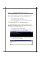
2.4.1 Using TELNET via Ethernet interface
To access the command line interface via Ethernet interface, you can use
TELNET to log in the Router from the local Ethernet network using the
Ethernet IP address that assigned to your xDSL Router. The Ethernet IP of
the xDSL Router is default set to 192.168.7.1.
1.
2.
Select Start->Programs->MS-DOS Prompt.
Find the IP address of the Router’s Ethernet port. Then use
TELNET to login the Router. For example, TELNET
192.168.7.1
3.
You will see that a telnet dialog pops up asking for password
(case sensitive), then enter admin ↵
Heritage Series ADSL Bridge/ Router
Installing and Configuring your xDSL Router
2-13
4.
Then you will see the following prompt, DSL >
5.
Now you are ready to configure the Router by using command.
Please contact your ISP/NSP to obtain the detail command sets of
your Router. If the Router does not return any message, refer to
Appendix B for troubleshooting information.
2.4.2 Using terminal program via serial console port
A terminal can be connected directly to the Serial console port. This
requires the use of a terminal emulation software package such as
Microsoft HyperTerminal. By default setting, the Router is configured to
communicate at a baud rate of 9600. Any standard terminal that support
baud rate of 9600 can be connected to the Router’s console port. Please
configure your serial port as:
BPS :
9600
Data bits :
8
Parity
:
None
Stop Bits :
1
Flow Control :
None
Following steps provide the instructions to log on to the Router via
Microsoft HyperTerminal.
1.
Select Start->Programs->Accessories->HyperTerminal
2-14
Installing and Configuring your xDSL Router
2.
Enter a connection name and click OK
3.
Select properly COM port and click OK
Heritage Series ADSL Bridge/ Router
Installing and Configuring your xDSL Router
2-15
4.
Enter the following parameters :
Bits per second
9600
Data bits
8
Parity
None
Stop bits
1
Flow Control
None
Then click OK
6.
When the HyperTerminal window appears, you must press the
enter key several time to get the command prompt for the
Router’s command line interface.
7.
Now you are ready to configure the Router by using command.
Please contact your ISP/NSP to obtain the detail command sets of
your Router. If the Router does not return any message, refer to
Appendix B for troubleshooting information.
2-16
Installing and Configuring your xDSL Router
Heritage Series ADSL Bridge/ Router
Basic Configurations
Chapter 3
3-1
Basic Configurations
This chapter contains configuration information, instructions and examples
for the basic link protocols that supported by the xDSL Router. The
information needed to configure the Router is depending on the chosen
link protocol. The link protocol is determined by your NSP(Network
Service Provider). Therefore, It is necessary to know the link protocol
which your NSP support before you refer to the configuration information
that will apply to your setup.
3-2
Basic Configurations
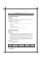
3.1 Factory default configuration
The Router is shipped with factory default settings. You may or may not
need to change them depend on what kind of network that your Router is
going to be installed.
Configuration item
Ethernet Interface
IP address
Network Mask
xDSL interface
IP address
Network Mask
ATM VPI/VCI number
Data Encapsulation Protocol
Machine Name
Domain name
DHCP Server
DHCP Client
DNS Relay
NAT
RIP
IP filtering
Bridge filtering
Spanning Tree
Telnet login password
SNMP access password
Default settings of xDSL Router
192.168.7.1
255.255.255.0
None
None
0/32
RFC1483
DSL
Disabled
Disabled
Disabled
Disabled
Disabled
Disabled
Disabled
Disabled
Disabled
admin
admin
Heritage Series ADSL Bridge/ Router
Basic Configurations
3-3
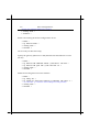
3.2 Bridged RFC1483
(Default configuration for Router)
[System configuration]
//
r1483
Ethernet Port
192.168.7.2
[ISP/DSLAM configuration]
IP address :
192.168.7.3
Subnet mask :
255.255.255.0
Gateway :
None
[Local PC configuration]
IP address :
192.168.7.2
Subnet mask :
255.255.255.0
Gateway :
None
Ethernet Port
192.168.7.1
//r1483
DSLAM/NSP
192.168.7.3
The Router already default to support the RFC 1483. However, you can use
following procedure to reconfigure the Router to support the RFC 1483
again.
> ip device flush
> bridge device add edd
> bridge device add bun/port=r1483/rfc1483=true/mode=<x>/
txvpi=<y>/txvci=<z>/rxvpi=<y>/rxvci=<z>
(<x> is the encapsulation mode of RFC1483, it can be one of LlcBridged and
VcMuxBridged, and the setting of encapsulation mode is case sensitivity. <y> is
the VPI value, and <z> is the VCI value)
> config save
> restart
Basic Configurations
3-4
The following describes how to remove all configurations properly so that
we start from a fresh configuration.
>
>
>
>
isfs rm
isfs rm
isfs rm
restart
resolve↵
initbridge↵
initppp↵
↵
Heritage Series ADSL Bridge/ Router
Basic Configurations
3-5
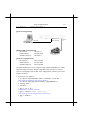
3.3 Routed RFC1483
[System configuration]
Ethernet Port
10.107.1.130
Ethernet Port
10.107.1.129
PC A
HUB
10.99.
48.50
Up-Link
PC B
10.107.1.131
10.99.48.1
DSLAM/ISP
10.107.1.132
PC C
PC N
[ISP/DSLAM configuration]
IP address :
10.99.48.1
Subnet mask :
255.255.255.0
Gateway :
10.99.48.50
[Local PC A configuration]
IP address :
10.107.1.130
Subnet mask :
255.255.255.248
Gateway :
10.107.1.129
[Local PC B configuration]
IP address :
10.107.1.131
Subnet mask :
255.255.255.248
Gateway :
10.107.1.129
> home ↵
(ignores any error message, just ensures back to root prompt)
> ip device add ethernet ether //edd 10.107.1.129 ↵
(set 10.107.1.129 as the IP address for your xDSL Router)
Basic Configurations
3-6
> ip device add mpoa ptp //bun/port=r1483/rfc1483=true/mode=<x>/
txvpi=<y>/txvci=<z>/rxvpi=<y>/rxvci=<z> 10.99.48.50↵
(assume 10.99.48.50 is the static IP address assigned by your service provider for
the PC); (<x> is the encapsulation mode of RFC1483, it can be one of LlcRouted
and VcMuxRouted, and the setting of encapsulation mode is case sensitivity. <y>
is the VPI value, and <z> is the VCI value)
> ip route add default 0.0.0.0 10.99.48.1 0:0:0:0 ↵
(10.99.48.1 is the IP address of your service provider)
> ip relay all↵
(enable routing between rfc1483 and ethernet ports)
config save ↵
restart ↵
You can use following procedure to remove existing RFC 1483 setting.
>
>
>
>
isfs rm
isfs rm
isfs rm
restart
resolve↵
initbridge↵
initppp↵
↵
Heritage Series ADSL Bridge/ Router
Basic Configurations
3-7
3.4 Classical IP (RFC1577)
[System configuration]
Ethernet Port
202.1.136.254
Ethernet Port
192.168.
1.2
202.1.136.100
[ISP/DSLAM Configuration]
IP Address :
192.168.1.1
Subnet Mask :
255.255.255.0
Default Gateway :
192.168.1.2
DSLAM/NSP
192.168.1.1
[Local PC Configuration]
IP Address :
202.1.136.100
Subnet Mask :
255.255.255.0
Default Gateway :
202.1.136.254
The following describes how to remove all configurations properly so that
we start from a fresh configuration.
Remove all existing bridge module configuration
>
>
>
>
home ↵
config reset bridge ↵
config save ↵
restart ↵
Remove all existing router module configuration
>
>
>
>
home ↵
ip device flush ↵
ip norelay ↵
ip ipatm pvc delete ipoa r1483 0/32 ↵
Basic Configurations
3-8
(use the same VPI/VCI of RFC 1577 setting)
> config save ↵
> restart ↵
Remove all existing IP module configuration device
>
>
>
>
home ↵
ip device flush ↵
config save ↵
restart ↵
We are ready for RFC1577 setup
Specify the gateway (RFC1577 on ISP/DSLAM site and Ethernet on local
PC site)
>
>
>
>
>
home ↵
ip device add ethernet ether //edd 202.1.136.254 ↵
ip device add ipoa atm //atm 192.168.1.2 ↵
config save ↵
restart ↵
Enable forwarding between router interface
> home ↵
> ip relay all ↵
> ip ipatm pvc add ipoa r1483 x/y remoteip 192.168.1.1 ↵
(‘ x’ is the VPI, ‘ y’ is the VCI. Check with your service provider)
> config save ↵
> restart ↵
Heritage Series ADSL Bridge/ Router
Basic Configurations
3-9
3.5 PPP Over ATM (RFC2364)
[System configuration]
Ethernet
Ethernet Port
202.1.136.254
192.168.
1.2
202.1.136.100
[ISP/DSLAM Configuration]
IP Address :
192.168.1.1
Subnet Mask :
255.255.255.0
Default Gateway :
192.168.1.2
DSLAM/NSP
192.168.1.1
[Local PC Configuration]
IP Address :
202.1.136.100
Subnet Mask :
255.255.255.0
Default Gateway :
202.1.136.254
The xDSL Router also can be setup to support RFC 2364(PPP over ATM)
with following procedure. Before setup RFC 2364, you have to ensure
remove existing RFC 1483 or RFC 1577 configuration with the procedure
mentioned above.
• IP dial out over PPPoA
> ip device add Ethernet ether //edd 202.1.136.254 ↵
(This is the IP of Ethernet port of xDSL Router)
> ip device add ppp_device ether //ppp/DEVICE=1 ↵
> config save ↵
> restart ↵
> ppp 1 pvc 0 32 ↵
(Set channel 1 to VPI=0, VCI=32)
> ppp 1 welogin <name> <password> ↵
(This is the login name and password of PPP server)
> ppp 1 enable ↵
3-10
Basic Configurations
> config save ↵
> restart ↵
> ip relay all ↵
> config save ↵
> restart ↵
• Remote bridging over PPPoA
>
>
>
>
bridge device add edd ↵
bridge device add ppp/DEVICE=2 ↵
config save ↵
restart ↵
>
>
>
>
ppp 1 pvc 32 mac ↵
ppp 1 interface 2 ↵
ppp 1 enable ↵
restart ↵
The RFC 2364 configuration also can be removed by following procedure.
Please ensure to remove the RFC 2364 configuration before set the xDSL
Router to other configuration.
• IP dial out over PPPoA
> ip device flush ↵
> config save ↵
> restart ↵
>
>
>
>
>
ppp 1 pvc none ↵
ppp 1 welogin none ↵
ppp 1 interface 0 ↵
ppp 1 disable ↵
restart ↵
> ip norelay ↵
> config save ↵
> restart ↵
Heritage Series ADSL Bridge/ Router
Basic Configurations
• Remote bridging over PPPoA
> config reset bridge ↵
> config save ↵
> restart ↵
>
>
>
>
ppp 1 pvc none ↵
ppp 1 interface 0 ↵
ppp 1 disable ↵
restart ↵
3-11
3-12
Basic Configurations
Heritage Series ADSL Bridge/ Router
Basic Configurations
3-13
3.6 PPP Over Ethernet (RFC2516)
[System configuration]
Ethernet
Ethernet Port
202.1.136.254
192.168.
1.2
202.1.136.100
[ISP/DSLAM Configuration]
IP Address :
192.168.1.1
Subnet Mask :
255.255.255.0
Default Gateway :
192.168.1.2
DSLAM/NSP
192.168.1.1
[Local PC Configuration]
IP Address :
202.1.136.100
Subnet Mask :
255.255.255.0
Default Gateway :
202.1.136.254
The xDSL Router also can be setup to support RFC 2516(PPP over Ethernet)
with following procedure. Before setup RFC 2516, you have to ensure
remove existing RFC 1483 or RFC 1577 or RFC 2364 configuration with the
procedure mentioned above.
• IP dial out over PPPoE
> ip device add ethernet ether //edd 202.1.136.254 ↵
(This is the IP of Ethernet port of xDSL Router)
> ip device add ppp_device ether //ppp/DEVICE=1 ↵
> ppp 1 pppoe 0 32 ↵
(Set channel 1 to VPI=0, VCI=32)
> ppp 1 welogin <name> <password> chap↵
(This is the login name and password of PPP server)
> ppp 1 enable ↵
> config save ↵
> restart ↵
3-14
Basic Configurations
> ip relay all ↵
> config save ↵
> restart ↵
The RFC 2516 configuration also can be removed by following procedure.
Please ensure to remove the RFC 2516 configuration before set the xDSL
Router to other configuration.
> isfs rm resolve
> isfs rm initppp
> restart
Heritage Series ADSL Bridge/ Router
Advanced Configurations
4-1
Chapter 4 Advanced Configurations
This Chapter described the advanced features that are primarily intended
for experienced users and network administrators to perform network
management and more complex configurations.
Advanced Configurations
4-2
4.1 Add NAT to Classic IP, PPP over ATM or PPP
over Ethernet
NAT is an IP address conversion feature that translates a PC’s local
(internal) address into a temporary global (outside/Internet) IP address.
NAT is needed when a PC (or several PCs) on a Local Area Network wants
to connect to the outside Internet to get to a remote network: NAT swaps
the local IP address to a global IP address. Our version of NAT goes one
step further by allowing several PCs to share one single IP address to the
Internet, thus reducing connection costs. In effect, it allows a whole LAN to
connect to the Internet as a single user.
[System configuration]
Ethernet Port
Ethernet Port
PC 1
202.1.136.101
PC 8
202.1.136.108
[ISP/DSLAM configuration]
IP address :
192.168.102.3
Subnet mask :
255.255.255.0
Gateway :
None
[Local PC 1 configuration]
IP address :
202.1.136.101
Subnet mask :
255.255.255.0
Gateway :
202.1.136.254
[Local PC 8 configuration]
IP address :
202.1.136.108
Subnet mask :
255.255.255.0
Gateway :
202.1.136.254
HUB
Up-Link
DSLAM/NSP
Heritage Series ADSL Bridge/ Router
Advanced Configurations
4-3
The following command tell you how to adding a Network Address
Translation protocol to the Classic IP(RFC1577) or PPP over ATM(RFC2364)
or PPP over Ethernet(RFC2516) configuration that mentioned above. The
following command must be added after the “ip device add …”
commands have been given and the Router restarted.
Enables NAT on a Classic IP (RFC1577)
> ip nat add ipoa ↵
Enables NAT on a PPP over ATM (RFC2364) or PPP over Ethernet
(RFC2516)
> ip nat add ppp_device ↵
Advanced Configurations
4-4
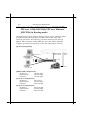
4.2 Enables NAT to RFC1483, Classic IP (RFC1577),
PPP over ATM (RFC2364), PPP over Ethernet
(RFC2516) in Routing mode
The xDSL Router can be setup to adding NAT protocol to a Routing Mode
configuration like RFC1483, RFC 1577, RFC 2364 or RFC 2516 with
following procedure. The following procedure must be typed after ip
device add command ( in RFC1483, RFC 1577, RFC 2364 or RFC2516
configure procedure) have been given and the xDSL Router restarted.
[System configuration]
Ethernet Port
202.1.136.254
Ethernet Port
PC 1
202.1.136.1
PC N
202.1.136.100
[ISP/DSLAM configuration]
IP address :
192.168.102.3
Subnet mask :
255.255.255.0
Gateway :
192.168.102.2
[Local PC 1 configuration]
IP address :
202.1.136.1
Subnet mask :
255.255.255.0
Gateway :
202.1.136.254
[Local PC 8 configuration]
IP address :
202.1.136.100
Subnet mask :
255.255.255.0
Gateway :
202.1.136.254
HUB
192.168
.102.2
Up-Link
192.168.102.3
DSLAM/NSP
Heritage Series ADSL Bridge/ Router
Advanced Configurations
4-5
• Add NAT to RFC 1483 to above RFC 1483 Routing Mode example
> ip nat add mpoa ↵
(ipoa is the device name same as you configure in RFC 1483 example)
• Remove NAT to RFC 1483 to above RFC 1483 Routing Mode example
> ip nat delete mpoa ↵
• Add NAT to RFC 1577 to above RFC 1577 Routing Mode example
> ip nat add ipoa ↵
(ipoa is the device name same as you configure in RFC 1577 example)
• Remove NAT to RFC 1577 to above RFC 1577 Routing Mode example
> ip nat delete ipoa ↵
• Add NAT to RFC 2364/RFC2516 to above RFC 2364/RFC2516 Routing
Mode example
> ip nat add ppp_device ↵
(ppp_device is the device name same as you configure in RFC 2364/RFC2516
example)
• Remove NAT to RFC 2364/RFC2516 to above RFC 2364/RFC2516
Routing Mode example
> ip nat delete ppp_device ↵
Advanced Configurations
4-6
4.3 Changing DHCP server configuration
DHCP is used to acquire IP addresses and options (such as the subnet
mask, DNS, gateway, etc.) automatically. On the practical level, acquiring
these initialization parameters with DHCP translates into avoiding the
more involved Router/PC process (reconfiguration of Router and/or PC
addresses in the same network.
[System configuration]
Ethernet Port
PC 1
202.1.136.1
Ethernet Port
202.1.136.254
HUB
PC N
202.1.136.100
[ISP/DSLAM configuration]
IP address :
Subnet mask :
Gateway :
[Local PC configuration]
IP address :
Subnet mask :
Gateway :
192.168
.102.2
Up-Link
192.168.102.3
DSLAM/NSP
192.168.102.3
255.255.255.0
None
None (obtained by DHCP)
None (obtained by DHCP)
None (obtained by DHCP)
By default, the xDSL Router is configured as a DHCP server with the
following settings :
% Do not allocate dynamic IP addresses to unknown clients
deny unknown-clients;
% Do not repond to BOOTP queries
deny bootp;
Heritage Series ADSL Bridge/ Router
Advanced Configurations
4-7
% Use 255.255.255.0 as subnet mask for all clients in 10.0.0.0 subnet
subnet 10.0.0.0 netmask 255.255.255.0 {
% Range of dynamic IP addresses (change only the last digit)
range 10.0.0.2 10.0.0.5;
% If client does not request a specific lease time allocate 3600
% seconds
% (change as required)
default-lease-time 3600;
% If client requests specific expiration time, allocate 7200
% seconds
%(change as required)
max-lease-time 7200;
% Set clients default gateway to this (do not change)
option routers 10.0.0.1;
% Set clients primary/secondary DNS as these (change as required)
option domain-name-servers 206.13.28.12, 206.13.31.12;
% Set clients domain name as this (change as required)
option domain-name "pacbell.net";
}
% Use 255.255.255.248 as subnet mask for the IP addr 63.193.197.114
% Define subnet for the IP address used by NAT (change as needed)
subnet 63.193.197.114 netmask 255.255.255.248 {
}
The basic procedure to change the default setting is that you have to delete
the existing configuration and reentering new configuration.
> home ↵
> dhcpserver config ↵
(displays the current DHCP server configuration)
> dhcpserver config flush ↵
(deletes current DHCP server settings)
> dhcpserver config confirm ↵
(confirm the previous action)
> config save ↵
(save the new configuration)
> dhcpserver config ↵
(displays the current DHCP server configuration. Should be empty.)
Now add the new settings for DHCP server.
4-8
Advanced Configurations
> dhcpserver config add subnet 10.0.0.0 netmask 255.255.255.0 {
range 10.0.0.A 10.0.0.B; default-lease-time C; max-lease-time D;
option routers 10.0.0.1; option domain-name-servers
eee.fff.ggg.hhh, iii.jjj.kkk.lll; option domain-name “mmmm” } ↵
(A, B are integers in the range 2--255, C/D indicate time in
seconds,eee.fff.ggg.hhh/iii.jjj.kkk.lll are IP addresses of primary/secondary
DNS, mmmm is domain name. All these values are assigned by your
service provider.)
> dhcpserver config add subnet aaa.bbb.ccc.ddd netmask
eee.fff.ggg.hhh { } ↵
(aaa.bbb.ccc.ddd is the static IP address assigned by your service provider
for the PC, eee.fff.ggg.hhh is the subnet mask assigned by your service
provider to PC)
> dhcpserver config confirm ↵
(confirm the new configuration)
> config save ↵
(save the new configuration)
> restart ↵
(after restart new configuration will take effect)
Heritage Series ADSL Bridge/ Router
Advanced Configurations
4-9
4.4 Changing DHCP client configuration
[System configuration]
Ethernet Port
PC 1
202.1.136.1
Ethernet Port
202.1.136.xxx
HUB
Up-Link
PC N
202.1.136.100
[ISP/DSLAM configuration]
IP address :
Subnet mask :
Gateway :
[Local PC 1 configuration]
IP address :
Subnet mask :
Gateway :
192.168
.102.2
192.168.102.3
DSLAM/NSP
192.168.102.3
255.255.255.0
None
202.1.136.101
255.255.255.0
202.1.136.xxx
The basic procedure to change the current setting is that you have to delete
the existing configuration and reentering new configuration.
> home ↵
> dhcpclient config ↵
(displays the current DHCP client configuration)
> dhcpclient config flush ↵
(deletes current DHCP client settings)
> dhcpclient config confirm ↵
(confirm the previous action)
> config save ↵
(save the new configuration)
> dhcpclient config ↵
(displays the current DHCP client configuration. Should be empty.)
4-10
Advanced Configurations
Now add the new settings for DHCP client.
> ip device add Ethernet ether //edd dhcp ↵
> dhcpclient config add timeout 300; ↵
> dhcpclient config add retry 2000; ↵
> dhcpclient config add reboot 500; ↵
> dhcpclient config add backoff-cutoff 240; ↵
> dhcpclient config add interface “ethernet” { send
dhcp-client-identifier xx:xx:xx:xx:xx:xx; send dpch-lease-time 900; }
↵
(xx:xx:xx:xx:xx:xx is the Ethernet Mac address of your xDSL Router)
> dhcpclient config confirm ↵
(confirm the new configuration)
> config save ↵
(save the new configuration)
> restart ↵
(after restart new configuration will take effect)
Heritage Series ADSL Bridge/ Router
Advanced Configurations
4-11
4.5 PPTP Tunneling Configuration
The xDSL Router can be configured to supports PPTP as following
procedure. But the xDSL Router currently provides the PPTP Access
Concentrator (PAC) end of a PPTP tunnel. And the PC must run an OS,
which supports PPTP, providing a PPTP Network Server (PNS).
Windows 98, Me, 2000 or Windows XP provide.
• PPTP dial out
In the following example, the PC connects to the xDSL Router firstly must
be configured as:
IP address of PNS
Subnet mask of PNS
Gateway of PNS
IP address of PAC
: 192.168.10.1
: 255.255.255.0
: 192.168.10.2
: 192.168.10.2
> ip device add Ethernet ether //edd 192.168.10.2 ↵
> config save ↵
> restart ↵
> ppp 2 pvc 0 32 ↵
(Set channel 2 to VPI=0, VCI=32)
> ppp 2 interface 0 ↵
> ppp 2 tunnel 1 pptp out ↵
> ppp 2 enable ↵
> pptp bind 192.168.10.2 ↵
> pptp 1 create listen ↵
> config save ↵
> restart ↵
Advanced Configurations
4-12
• PPTP dial in
In the following example, the PC connects to the xDSL Router firstly must
be configured as:
IP address of PNS
Subnet mask of PNS
Gateway of PNS
IP address of PAC
: 192.168.10.1
: 255.255.255.0
: 192.168.10.2
: 192.168.10.2
> ip device add Ethernet ether //edd 192.168.10.2 ↵
> config save ↵
> restart ↵
> ppp 2 pvc 0 32 listen ↵
(Set channel 2 to VPI=0, VCI=32)
> ppp 2 interface 0 ↵
> ppp 2 tunnel 1 pptp in ↵
> ppp 2 enable ↵
>
>
>
>
pptp bind 192.168.10.2 ↵
pptp 1 create 192.168.10.1 ↵
config save ↵
restart ↵
The PPTP configuration can be removed by following procedure. Please
ensure to remove the PPTP configuration before set the xDSL Router to
other configuration
• Remove PPTP either dial out or dial in
> ip device flush ↵
> config save ↵
> restart ↵
>
>
>
>
ppp
ppp
ppp
ppp
2
2
2
2
pvc none ↵
interface 0 ↵
tunnel 0 ↵
disable ↵
> pptp 1 delete ↵
Heritage Series ADSL Bridge/ Router
Advanced Configurations
> pptp bind none ↵
> config save ↵
> restart ↵
4-13
4-14
Advanced Configurations
Heritage Series ADSL Bridge/ Router
Managing the xDSL Router
Chapter 5
5-1
Managing the xDSL
Router
5.1 Booting the xDSL Router from Ethernet Network
By default, the Router is configured to boot from the on-board flash
memory. But it is possible boot via Ethernet network as well. The
executable image is stored in the local PC and is downloaded to the Router
via Ethernet network upon every reset. For this, the Router needs to be
configured and also a TFTP/BOOTP utility needs to be installed on the
local PC.
!
Router Configuration
# Turn off the Router and turn it on again
# Keep the * key be pressed
# At the ‘Boot from Ethernet, USB or Flash? (E/U/F)’
prompt type E ↵
!
Local PC Configuration
To download the software you need a TFTP/BOOTP server.
You can use any. Be aware that every time the board is restarted
the image will be transferred from the local PC to the Router.
5-2
Managing the xDSL Router
5.2 Upgrading on-board flash memory from
Ethernet network
You can update the on-board flash memory after you booting the new
firmware from the Ethernet network by issue the following commands.
> home ↵
> flashfs rewrite boot.bin ↵
(this command is available for update boot code only)
> flashfs update ↵
> flashfs ls ↵
You should see some messages about the file name and file sizes that
stored in the Router. If you get “no flash content” something went
wrong.
Heritage Series ADSL Bridge/ Router
Managing the xDSL Router
5-3
5.3 SNMP
The xDSL Router provides SNMP agent support standard MIBs.
SNMP is also used internally for configuration of the router. The active
SNMP agent within the Router accepts SNMP requests for status, statistics,
and configuration updates. Communication with the SNMP agent occurs
over the LAN or WAN connection. Any management application using
SNMP over UDP/IP (User Datagram Protocol/Internet Protocol) has
access to the local SNMP agent. The following MIBs are supported:
!
!
!
!
!
!
MIB II (RFC 1213)
Bridge MIB (RFC 1493)
PPP/LCP MIB (RFC 1471)
PPP/Security MIB (RFC 1472)
PPP/IP MIB (RFC 1473)
PPP/Bridge MIB (RFC 1474)
5-4
Managing the xDSL Router
Heritage Series ADSL Bridge/ Router
xDSL Link Performance Statistics
Chapter 6
6-1
xDSL Link
Performance Statistics
To see the xDSL link performance statistics, you can use the serial console
port or the Ethernet interface to access the command line interface.
After power up wait till xDSL LED glows steadily. This condition indicates
Router has reached “SHOWTIME”. Now <dsl> process commands can be
issued at the ‘<dsl>’ prompt to retrieve various measurements. Refer to
chapter 7 for the details of <dsl> process commands.
6-2
xDSL Link Performance Statistics
Heritage Series ADSL Bridge/ Router
Command Sets for Command Line Interface
Chapter 7
7-1
Command Sets for
Command Line
Interface
Command line interface conventions
!
!
!
!
!
Command line length may be up to 90 characters long.
The command line interface is case-sensitive
Parameters in between [ and ] are optional
Parameters in between < and > must be entered
The command line interface prompts for commands with a prompt
that indicates the identity of the system. It determines how to
indicate the identity as follows :
# If the SNMP MIB variable sysName.0 exists and is
non-empty, that is used first;
# Otherwise, if a local IP address exists, that is used;
# Otherwise, the local MAC address is used.
For example, the prompt might look like one of the following
DSL>
192.168.7.1>
0:30:eb:ff:0:ff>
Command Sets for Command Line Interface
7-2
Basic system command sets
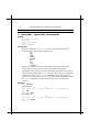
1. <process>, <process> <command>
Syntax:
<process> <command>
<process>
<process> version
home
home <command>
Description:
In these commands, “<process>” can be any of a list of process
names known to the console as following :
ip
ppp
snmp
config
bridge
nat
dsl
isfs
flashfs
The former variant sends the command to the process. The latter
variant remembers the process name, and sends subsequent
commands to the process, as if they had been preceded by the process
name, until the command “home” is issued. The prompt is changed to
reflect this; moreover, if a “help” command with no arguments is
issued, it is passed to the process as usual, but then information about
the “home” command is appended to the process’s output by the
console.
Example:
DSL> isfs help
Commands are:
ls
rm
Type 'help all' or 'help
DSL> isfs
DSL isfs> help
Commands are:
ls
rm
Type 'help all' or 'help
DSL isfs> home
DSL>
cat
<command>' for more details
cat
<command>' for more details
Heritage Series ADSL Bridge/ Router
Command Sets for Command Line Interface
7-3
When the console is at the prompt of a particular process, the
command "home <command>" or "home <process> <command>" may be
used to execute a command as if the user had typed "home" followed
by "<command>" or "<process> <command>". However, the console
will remain at the same process prompt. The command "home
<process>" will change the prompt from the current process to a new
process "<process>".
Example:
DSL> conifg
DSL config> help
Commands are:
print
reset
save
Type 'help all' or 'help <command>' for more details
DSL config> home help
Commands are:
dsl
bridge
config
flashfs
ip
isfs
nat
ppp
restart
snmp
system
Type 'help all' or 'help <command>' for more details
DSL config> home flashfs help
Commands are:
cat
ls
update
Type 'help all' or 'help <command>' for more details
DSL config> home isfs
DSL isfs> help
Commands are:
ls
rm
cat
Type 'help all' or 'help <command>' for more details
DSL isfs> home
DSL>
2. help
Syntax:
help
help <cmd>
help all
<process> help
<process> help <cmd>
<process> help all
Description:
Displays a summary of available commands, more detailed
information on a particular command, or more detailed information
on all commands.
Example:
Command Sets for Command Line Interface
7-4
DSL> ip help
Commands are:
arp
config
device
disable
enable
help
ipatm
nat
norelay ping
relay
rip
route
routes
stats
subnet
Type "help all" or "help <command>" for more details
DSL> ip help arp
arp syntax:
arp <cmd> - execute arp subcommand
arp help - list subcommands available
3. . (history mechanism)
Syntax:
.
Description:
Repeats the previous console command.
Example:
DSL> ip help arp
arp syntax:
arp <cmd>
arp help
DSL> .
arp syntax:
arp <cmd>
arp help
- execute arp subcommand
- list subcommands available
- execute arp subcommand
- list subcommands available
4. restart
Syntax:
restart
Description:
Reboots the Router
5. system
Syntax:
system
Description:
Displays the system type, firmware version and other information.
Heritage Series ADSL Bridge/ Router
Command Sets for Command Line Interface
7-5
Commands for ISFS and FLASHFS process
1. ISFS and FLASHFS overview
The Router requiring storage of configuration data should make use of the
ISFS file system. The FLASHFS file system provides permanent storage of
files and is not normally used other than at start of day or when re-writing
the FLASH. In addition to configuration files, FLASHFS stores the
firmware image, which is loaded after system restart.
After system restart and during system initialization, FLASHFS files are
copied into ISFS so that they are accessible by application processes.
Typically, applications use the ISFS files to store their configuration data.
Changes made to the configuration can be written back into ISFS, and
subsequently FLASHFS, with the ‘config save’ command. During a
FLASHFS update, all configuration files in ISFS are written back to FLASH
irrespective of whether they have changed or not.
Normally the firmware image is not rewritten. The FLASHFS configuration
files can be considered the ‘master’ copies, and the ISFS files the run time
copies. If the ISFS copies are written back to the FLASHFS, the current
settings will be preserved. It is possible to read files from FLASHFS directly
though this use is deprecated.
2. isfs cat | flashfs cat
Syntax:
isfs cat <file>
flashfs cat <file>
Description:
The cat command allows a console user to view the contents of the
specified file. Only printable characters are displayed, non-printable
characters are represented by a ‘.’ character. Printable characters
include all standard printable characters together with carriage return,
line feed, and tab.
No output formatting is performed, and no scroll lock function
implemented.
Example:
cat ipaddresses
Command Sets for Command Line Interface
7-6
3. isfs ls | flashfs ls
Syntax:
isfs ls
flashfs ls [-l]
Description:
The ls command allows a console user to list the files present in the
filesystem.
The FLASHFS ‘-l’ option displays more detailed information (logical
address within FLASH and linked list information).
Example:
ls
4. isfs rm
Syntax:
isfs rm <file>
Description:
The rm command allows the user to remove a file from the ISFS file
system. The memory used to store the file is freed .A subsequent
FLASHFS update will write the new, shorter, ISFS files into FLASHFS,
providing an implicit rm function for FLASHFS.
Note: If the file removed is the only file that would be stored in
FLASHFS as type ‘fixed’, the file will remain in FLASHFS as the
fixed file area will not be re-written during an update.
Example:
> isfs rm foo
5. flashfs update
Syntax:
flashfs update
Description:
The ‘update’ command instructs FLASHFS to update the FLASH
memory from the files contained in the ISFS file system.
Example:
> flashfs update
Heritage Series ADSL Bridge/ Router
Command Sets for Command Line Interface
7-7
Commands for Bridge process
1. device add
Syntax:
device add <device>
Description:
This command adds a device to the bridge configuration. Attempts to
add the bridge itself or an existing device to the bridge are rejected.
Attempts to add unsupported devices are rejected. There is a limit on
the number of devices that can be attached to the bridge. If a device is
successfully added to the bridge, it will only become active after the
configuration is saved and the system is rebooted. If the device being
added is from a process which supports multiple devices, the
/DEVICE attribute must be specified as part of the device name. The
table below shows devices, which may be attached to the bridge,
although not all systems may support all devices.
lec1
Forum LAN emulation alecjade
edd
Ethernet driver bun_ethernet
Point-to-Point protocol pp
ppp
Configuration saving saves this information.
Example:
DSL bridge> device add edd
DSL bridge> device add ppp/DEVICE=2
2. device delete
Syntax:
device delete <device>
Description:
This command deletes a device from the bridge configuration. The
changes will only take place after the configuration is saved and the
system is rebooted. The syntax of the device name is the same as that
for the device add command.
Configuration saving saves this information.
Example:
DSL bridge> device delete edd
Command Sets for Command Line Interface
7-8
3. device list
Syntax:
device list
Description:
This command lists all the devices that are currently attached to the
bridge. It does not show the stored configuration (which can be seen
with the config print command).
Example:
DSL bridge> device list
4. ethertype
Syntax:
ethertype [<port> any|ip|pppoe]
Description:
This command enables filtering of Ethernet packets according to the
ETHER_TYPE field in the header. Only packets of the type specified
using this command will be sent on the port specified; packets of all
types will always be received. By default, all bridge ports are set to
“any”, which means that the type of the packet will never be checked.
The meaning of the other options is as follows:
Option
“ip”
“pppoe”
Permitted ETHER_TYPE values
0x0800 – IP
0x0806 – ARP
0x8863, 0x8864 – PPP Over Ethernet (RFC 2516)
The port is specified as an integer, as displayed by the device list
command. When using this command in the initbridge
configuration file, ports are numbered in the order in which the
device add commands are given, starting from 1.
If no arguments are given, the current settings for each port are
displayed.
Example:
DSL bridge> ethertype 2 any
Heritage Series ADSL Bridge/ Router
Command Sets for Command Line Interface
7-9
5. filter
Syntax:
filter
Description:
This command shows the current contents of the bridge’s filter table.
The MAC entries for each device are shown in turn together with the
time that the MAC address was last seen by the bridge. The command
also shows the current filter ageing time, in seconds, and the number
of creation failures since the system was started. Creation failures
occur when there is no room left in the filter table for a new entry.
Example:
DSL bridge> filter
6. filterage
Syntax:
filterage [<age>]
Description:
This command sets, or displays if no arguments are given, the filter
table ageing time. The ageing time is the time after which MAC
addresses are removed from the filter table when there has been no
activity. The time is specified in seconds and may be any integer
value in the range 10…100,000 seconds. This value may also be
changed through SNMP. Changing the value of filterage has
immediate effect.
Configuration saving saves this information. By default the filter
ageing time is set to 300 seconds.
Example:
DSL bridge> filterage
6. flush
Syntax:
flush [<port>]
Description:
This command allows the MAC entries for a specified port, or all
ports, to be removed from the filter table. The port number for a
device may be determined using the device list or status
commands. If the port number is omitted, all entries for all ports are
removed from the filter table.
Example:
DSL bridge> flush
Command Sets for Command Line Interface
7-10
7. portfilter
Syntax:
portfilter [<source port> all|<destination ports>]
Description:
The portfilter command allows control over the bridge’s
forwarding and broadcasting behavior. By default, when a multicast
or an unknown packet is received on a port (referred to above as the
source port), it will be forwarded to all other bridge ports (referred to
above as the destination ports). Each bridge port may have its
behavior modified separately. The first example below configures the
bridge so that packets arriving on port 2 will only be forwarded to
ports 3, 4 and 5, and packets arriving on port 3 will only be forwarded
to port 1. All other ports retain their default behavior. Note that this
command does not force packets arriving on the source port to be
sent to all specified destination ports. The bridge retains its learning
behavior, so unicast packets, once their destination is known to the
bridge, will still only be sent to one port. Note also that the bridge
itself (for example when attached to the IP router) will always
forward to all ports, and will always be forwarded to by all ports. The
default behavior can be restored by calling this command with the
argument “all”, as shown in the second example. The ports are
specified as integers, as displayed by the device list command.
When using this command in the initbridge configuration file, ports
are numbered in the order in which the device add commands are
given, starting from 1. If no arguments are given, the current settings
for each port are displayed.
Example 1:
DSL bridge> portfilter 2 3 4 5
DSL bridge> portfilter 3 1
Example 2:
DSL bridge> portfilter 2 all
DSL bridge> portfilter 3 all
Heritage Series ADSL Bridge/ Router
Command Sets for Command Line Interface
7-11
8. status
Syntax:
Status
Description:
This command shows the status of the bridge and its ports. The status
information for a port includes the SNMP type information about
time exceeded packets, packets discarded, etc. It also includes the
broadcast history of the port over the last five seconds and the high
water mark of packets queued on the bridge for this device.
Example:
DSL bridge> status
9. spanning disable | enable
Syntax:
spanning disable
spanning enable
Description:
When spanning tree operation is disabled, the bridge operates in
transparent mode and all bridge ports are set to the forwarding state.
When spanning tree operation is enabled, the state of the bridge’s
ports is controlled by the spanning tree process.
The status command reports the state of the spanning tree process.
Configuration saving saves this information. By default, spanning
tree operation is enabled.
Example:
DSL bridge> spanning disable
DSL bridge> spanning enable
10. spanning forwarddelay
Syntax:
spanning forwarddelay [<time>]
Description:
Reads or sets the time in seconds, in which the bridge remains in the
listening or learning states, and is used when the bridge is or is
attempting to become the root bridge. The forward delay time may be
any value between 4 and 30 but it is also constrained by the
maximum age and hello times. The forward delay time may also by
changed by SNMP command. The maxage, hellotime and
forwarddelay times are constrained as follows:
Command Sets for Command Line Interface
7-12
2 × (forwarddelay - 1) ≥ maxage
maxage ≥ 2 × (hellotime + 1)
Configuration saving saves this information. By default the forward
delay time is set to 15 seconds.
Example:
DSL bridge> spanning forwarddelay 10
;Sets the forwarding
delay to 10 seconds.
11. spanning hellotime
Syntax:
spanning hellotime [<time>]
Description:
Reads or sets the time in seconds, after which the spanning tree
process sends notification of topology changes to the root bridge, and
is used when the bridge is or is attempting to become the root bridge.
The hello time may be any value between 1 and 10 and is also
constrained by the forwarddelay and maxage times. The hello time
may also be changed by SNMP command.
Configuration saving saves this information. By default the hello time
is set to 2 seconds.
Example:
DSL bridge> spanning hellotime 5
;Sets the hello time
to 5 seconds
12. spanning maxage
Syntax:
spanning maxage [<time>]
Description:
Reads or sets the maximum age of received spanning tree protocol
information before it is discarded, and is used when the bridge is or is
attempting to become the root bridge. The maxage time may be any
value between 6 and 40 and is also constrained by the forwarddelay
and hellotime times. The maxage time may also be changed by SNMP
command.
Configuration saving saves this information. By default the maxage
time is set to 20 seconds.
Example:
DSL bridge> spanning maxage 6
;Sets the maxage
time to 6 seconds
Heritage Series ADSL Bridge/ Router
Command Sets for Command Line Interface
7-13
13. spanning port <number>
The port commands, described in subsequent sections, control the
configuration of the bridge’s ports so far as the operation of the
spanning tree protocol is concerned. Ports are numbered from 1.
Every port on the bridge may be specified by typing all instead of a
port number.
14. spanning port <number> disabled | enable
Syntax:
spanning port <number> disable | enable
Description:
Allows a port to be disabled or enabled. The state of a port may also
be changed by SNMP command. A port, which is enabled will take
part in the operation of the spanning tree protocol. If enabled, the
physical port may be “enabled” or “disabled” as demanded by the
operation of the protocol.
Configuration saving saves this information. By default ports are
enabled.
Example:
DSL bridge> spanning port 1 enable ;Enables port 1 on
the bridge.
15. spanning port <number> pathcost
Syntax:
spanning port <number> pathcost [<cost>]
Description:
Reads or sets the cost of using this port. The cost may be any number
between 1 and 65535. The cost of the port is used when deciding
which is the best path to the root bridge. The cost of a port may also
be changed by SNMP command.
Configuration saving saves this information. By default a cost of 10 is
assigned to a port
Example:
DSL bridge> spanning port 2 pathcost
;Displays the path
cost for port 2 on the
bridge
Command Sets for Command Line Interface
7-14
16. spanning port <number> priority
Syntax:
spanning port <number> priority [<portpriority>]
Description:
Reads or sets the priority of the port. The priority may be any value
between 0 and 255. The priority is used in conjunction with the
pathcost to determine the best root to the root bridge. The higher the
priority number, the less significant, in protocol terms, the port. The
port priority may also be changed by SNMP command.
Configuration saving saves this information. By default a port has a
priority of 128.
Example:
DSL bridge> spanning port 1 priority
;Displays the
priority for port 1
on the bridge
17. spanning priority
Syntax:
spanning priority [<bridgepriority>]
Description:
Reads or sets the priority of the bridge. The priority may be any value
in the range 0 to 65535. The higher the priority number, the less
significant, in protocol terms, the bridge. Where two bridges have the
same priority, their MAC address is compared and the smaller MAC
address is treated as more significant. The priority of the bridge may
be changed by SNMP command.
Configuration saving saves this information. By default the bridge is
assigned a priority of 32768.
Example:
DSL bridge> spanning priority 4000 ;Sets the bridge
priority to 4000.
Heritage Series ADSL Bridge/ Router
Command Sets for Command Line Interface
7-15
18. spanning status
Syntax:
spanning status
Description:
Reports the status of the spanning tree. If spanning tree operation is
disabled, a message is printed to that effect and no other information
is displayed. When spanning tree operation is enabled, the following
information is displayed:
• The identifier of the bridge.
• The identifier of the root bridge.
• The root port for this bridge.
• The root path cost: how far the bridge is from the root
• The various spanning tree time values as defined by the current
root bridge:
• The maximum age of spanning tree information before it is
discarded: max age time.
• The amount of time between configuration protocol packets: hello
time.
• The amount of time delay when ports are changing state: forward
delay time.
• For each port:
• The identifier of the designated bridge
• The identifier of the designated port for the designated bridge
• The identifier of the designated root bridge
Example:
DSL bridge> spanning status
Command Sets for Command Line Interface
7-16
Commands for DHCP server process
1. dhcpserver config
Syntax:
dhcpserver config [add <text>|confirm|delete|flush]
Description:
This command displays or edits the current configuration of the
DHCP server. To display current configuration, provide no
arguments to the command. Use of the “add” argument adds the line
<text> to the configuration file. Use of the “confirm” argument
reparses the configuration file, confirming the changes made if the
parse is successful. Use of the “delete” argument deletes the last line
from the configuration file. Use of the “flush” argument deletes the
whole configuration. Following any change to the configuration file, it
is necessary to “confirm” the changes, issue a “flashfs update” to
commit the change to FLASH, and then restart the system before the
changes can take effect.
Example:
DSL> dhcpserver config
--Current DHCP server configuration
--allow unknown-clients;
allow bootp;
subnet 192.168.219.0 netmask 255.255.255.0 {
range 192.168.219.10 192.168.219.30;
max-lease-time 5000;
}
DSL> dhcpserver config flush
Configuration file flushed.
DSL> dhcpserver config
--Current DHCP server configuration
(Issue "dhcpserver config confirm" followed by "flashfs
update" to confirm new configuration)
--DSL>
Heritage Series ADSL Bridge/ Router
Command Sets for Command Line Interface
7-17
2. dhcpserver status
Syntax:
dhcpserver status
Description:
This command provides a summary of all leases known to the server
on each interface in turn. It also shows remaining available IP
addresses (i.e. those with no specified lease time, or client identifier).
Example:
DSL> dhcpserver status
DHCP Server Lease Status
Interface “ethernet”
IP address
Client UID
Expiry
192.168.219.1
01:00:20:af:20:6f:59
11 hours
192.168.219.2
01:00:20:af:11:2a:ac
8 hours
192.168.219.3
Myclient
140 seconds
192.168.219.4
00:20:af:20:00:2b:43
2 days
192.168.219.5
<unknown>
Never
192.168.219.6
<unknown>
Never
192.168.219.7
<unknown>
Never
192.168.219.8
<unknown>
Expired
192.168.219.9
<unknown>
Expired
192.168.219.10 Foobarbozzle
Expired
Command Sets for Command Line Interface
7-18
Commands for DHCP Client process
1. dhcpclient config
Syntax:
dhcpclient config
Description:
This command displays the current configuration of the DHCP client,
including selected DHCP options.
Example:
DSL> dhcpclient config
--DHCP client configuration file: ‘//isfs/dhclient.conf’
timeout 60;
retry 60;
reboot 10;
backoff-cutoff 40;
interface “ethernet” {
send dhcp-lease-time 5000;
send dhcp-client-identifier “Galapagos”;
}
2. dhcpclient status
Syntax:
dhcpclient status [all]
Description:
This command provides DHCP status information for the active
bound lease associated with each valid interface in turn, including IP
address, time until lease renewal, subnet mask and DHCP server
address. Including the “all” flag shows, for each valid interface, the
active lease, leases which are being, or have been offered to the
interface, and any leases which are still being held by the client which
are not currently active (since a single interface can only have one
active lease at a time).
Example:
DSL> dhcpclient status
DHCP Client Lease Status (active lease only)
Interface ’ethernet’
Status
Server ID
IP address
Subnet mask
Renewal
*ACTIVE* 192.168.219.151 192.168.219.1 255.255.255.0 31 seconds
3. ip device
Heritage Series ADSL Bridge/ Router
Command Sets for Command Line Interface
7-19
Syntax:
ip device add <i/f> <type> <file> [mtu <size>] [<IP
address>|dhcp]
ip device
Description:
The ip device add command adds an interface to the configuration of
the IP stack. The last parameter of the command would normally the
IP address of the interface; use of the string dhcp causes the IP
address to be discovered by the DHCP client software. Note that
using the flag dhcp on an interface precludes running a DHCP server
on that interface! The ip device command lists the current
configuration of any devices attached to the IP stack. A device
configured to use DHCP will show “dhcp” in the “IP address” column,
followed by the actual IP address discovered and bound by DHCP, if
any. For interfaces configured to use DHCP, saving configuration
only marks the interface as using DHCP; it does not save the actual IP
address discovered by DHCP, which must be renewed.
Example:
DSL> ip device add ethernet ether //edd dhcp
…DHCP then discovers the IP address for the interface…
DSL> ip device
# type dev file IP address
device ethernet ether //edd mtu 1500 dhcp
Commands for IP process
Command Sets for Command Line Interface
7-20
1. arp
Syntax:
arp
arp
arp
arp
arp
add <i/f> <IP address> <MAC address>
delete <i/f> <IP address>
flush
[list]
help [all|<cmd>]
Description:
Allows display and manipulation of the ARP table: the list of IP
addresses and corresponding MAC addresses obtained by ARP on
Ethernet-like interfaces. Normally there is no need to add entries to
the table with “arp add”, since they should be discovered by the
ARP protocol. Displaying the table with “arp list” (or just “arp”)
is sometimes useful, and deleting an entry with “arp delete”, or the
whole table with “arp flush”, can sometimes speed up recovery
from temporary problems if something unusual has happened.
Entries added with “arp add” do not time out like those discovered
by use of the ARP protocol, but they are deleted by “arp flush” and
will not survive a restart (they are not saved by configuration saving).
Note that the ARP table is used only for destinations on directly
connected Ethernet-like networks, not for those reached through
routers (although the ARP table may be used to discover the MAC
address of the router).
Example:
DSL> ip arp add ether 192.168.50.1 8:0:20:19:9A:D9
DSL> ip arp
arp add flane 192.168.2.63 00:20:2b:e0:03:87 # 8m58s
arp add flane 192.168.2.109 00:20:2b:03:08:b1 # 2m24s
arp add ether 192.168.50.1 08:00:20:19:9a:d9 # forever
arp add ether 192.168.50.57 00:20:af:2e:fa:3c # 3m25s
DSL> ip arp delete flane 192.168.2.109
DSL> ip arp list
arp add flane 192.168.2.63 00:20:2b:e0:03:87 # 8m46s
arp add ether 192.168.50.1 08:00:20:19:9a:d9 # forever
arp add ether 192.168.50.57 00:20:af:2e:fa:3c # 3m13s
DSL> ip arp flush
DSL> ip arp
# flane ARP table is empty
# ether ARP table is empty
DSL> ip arp
arp add flane 192.168.2.108 00:20:2b:03:0a:72 # 10m58s
# ether ARP table is empty
(The last example shows that the MAC address for 192.168.2.108 has
Heritage Series ADSL Bridge/ Router
Command Sets for Command Line Interface
7-21
been automatically added again, having been discovered by means of
the ARP protocol.)
2. config
Syntax:
config [save]
Description:
Displays the IP configuration (not including the “snmp”
configuration), or saves it in flash memory. The functionality of the
“config” command is also accessible in the standard way through
the config process (e.g. “config print ip”), if that process is
present. However, when accessed through the config process, the
“snmp” configuration is included.
Example:
DSL> ip config
device add ether ether //nice mtu 1500 192.168.2.1
device add vlane ether //lane mtu 1500 192.168.55.1
subnet add vlane.home . 192.168.55.0 ff:ff:ff:00
subnet add ether.home . 192.168.2.0 ff:ff:ff:00
rip send ether 2
rip send vlane 2
rip accept ether 1 2
rip accept vlane 1 2
autoloop on
route add default 0.0.0.0 192.168.2.7 00:00:00:00 2 # MAN
relay ether ether
relay ether vlane
relay vlane vlane
ipatm lifetime 60
# IP host table:
# Port table:
router 520/UDP
snmp 161/UDP
tftp 69/UDP
telnet 23/TCP
DSL> ip config save
Updating flash filing system ...
done
ip: configuration saved
3. device
Syntax:
device
7-22
Command Sets for Command Line Interface
device add <i/f> <type> [<file>] [mtu <size>] [<IP address>]
device delete <i/f>
device flush
Description:
Displays the interfaces that IP is configured to use, or adds an
interface to the configuration, or deletes an interface, or all interfaces,
from the configuration. However, the commands to change the
configuration do not take effect immediately (except when the
“device add” command is run at start-up from the initialisation file).
It is necessary to save the configuration (e.g. with “ip config save”)
and restart the system (e.g. with “ip restart”) before they take
effect. “device” will display both the current interfaces and those
that have been configured but are not yet in effect. (Other commands
apply only to the devices in effect, rather than to those configured;
when adding a device, for example, one may need to issue the
“device add” command, then the “config save” and reboot, then
issue any other configuration commands that depend on the existence
of the device, and then “config save” again.)
“<i/f>” is an arbitrary label for the interface, which is used in
referring to it in subsequent commands. (It is often chosen to be the
same as “<type>”, though this is perhaps slightly confusing.)
“<type>” specifies the class of interface: Ethernet-like, IP-over-ATM,
or loopback. For an Ethernet-like or IP-over-ATM interface,
“<file>” specifies the file name that will be opened to access the
underlying device. For a loopback interface, “<file>” is not used,
and can just be specified as “-“ or omitted altogether.
Several different values of “<type>” specify the same class of
interface; they differ in that each implies a different default value for
“<file>”. As a result, for the most common interface configurations,
“<file>” can be omitted, and one need only specify the appropriate
value of “<type>”. The supported values for “<type>” are
Class
Ethernet
<type>
ether
Default file
//nice or
//ethernet or
Heritage Series ADSL Bridge/ Router
Command Sets for Command Line Interface
IP-over-ATM
vlane
flane
bridge
atm
atmpvc
loop
7-23
//edd
//lane
//lec1
//bridge
//q93b
//atm
-
Loopback
“<mtu>” specifies the MTU (maximum transmission unit); that is, the
size of the largest datagram (excluding media-specific headers) that IP
will attempt to send through the interface. The value specified will be
ignored if it is larger than the maximum supported by the interface
class, which is currently 1500 except for the loopback interface, unless
the IP-over-ATM MTU has been changed; normally there is no point
in setting the MTU less than this, so the “<mtu>” option is of little
use.
“<IP address>” is the IP address that this system uses on the
interface ; if it is not specified, the interface will be disabled until an IP
address is supplied with the “ip enable” command. For a loopback
interface, the address should be set to 127.0.0.1. (All addresses of the
form 127.*.*.* will then be recognized as loopback addresses, as is
normal practice.) For non-loopback interfaces, the subnet mask for the
local network will be assumed to be ff:ff:ff:00 (e.g. a class C network);
if the correct subnet mask is other than this then it will need to be set
with the “subnet” command.
If there is no initialisation file //isfs/resolve (or
//isfs/arptable) at all, then default interfaces are configured as if
by the “device” commands
device add ether ether //edd
device add ether ether //nice (otherwise)
device add atm atm //q93b
but in each case only if the file concerned ( “//edd”, “//nice”, or
“//q93b”) can be opened. Furthermore, if the IP process is given a
command line then each argument will be treated as a possible
Ethernet-like file to open, given names “ether1”, “ether2”, and so
on. For example, if the IP process is defined in the system file as
“Process ip is tcp_ip/ip //bridge //lec1 ” (and
“//bridge” and “//lec1” can be opened), then the equivalents of
the commands
device add ether1 ether //bridge
device add ether2 ether //lec1
will be processed, in addition to the others above.
Command Sets for Command Line Interface
7-24
Configuration saving saves the interface configuration.
Example:
DSL> ip device
# type dev file IP address
device ether ether //nice mtu 1500 192.168.2.1
device vlane ether //lane mtu 1500 192.168.55.1
DSL> ip device add loop loop 127.0.0.1
Change will have no effect until after config save and restart.
DSL> ip device delete vlane
Change will have no effect until after config save and restart.
DSL> ip device
# type dev file IP address
device ether ether //nice mtu 1500 192.168.2.1
device vlane ether //lane mtu 1500 192.168.55.1 # DELETED
device loop loop - mtu 2048 127.0.0.1 # ADDED
Additions/deletions will have no effect until after config
save and restart.
4. disable
Syntax:
disable [<i/f>]
Description:
Disables all interfaces, or just a specified interface.
Example:
DSL> ip disable vlane
DSL> ip device
# type dev file IP address
device ether ether //nice mtu 1500 192.168.2.1
device vlane ether //lane mtu 1500 192.168.55.1 # DISABLED
5. enable
Syntax:
enable [<i/f> [mtu <size>] [<IP address>]]
Description:
Enables all interfaces, or just a specified interface. Can also be used to
set the MTU and IP address on an interface when enabling it (or
change them on an interface that is already enabled); see the
“device” command for details on these.
Configuration saving saves the MTU and IP addresses, but not the
disabled/enabled state.
Example:
DSL> ip enable vlane 192.168.56.3
ip/vlane: IP address 192.168.56.3
Heritage Series ADSL Bridge/ Router
Command Sets for Command Line Interface
7-25
DSL> ip device
# type dev file IP address
device ether ether //nice mtu 1500 192.168.2.1
device vlane ether //lane mtu 1500 192.168.56.3
6. get
Syntax:
get <file>
Description:
Reads and executes commands from a file. The commands in the file
are in the same format as those documented in this chapter, with no
“ip” prefix. They can contain comments, introduced by the “#”
character. The “get” command is “hidden”, not shown by “ip
help”.
Example:
DSL> ip get //isfs/cmdfile
7. ipatm abort
Syntax:
ipatm abort <n>
Description:
Closes an IP-over-ATM SVC; the number <n> is as displayed by
“ipatm files”. If there is still traffic being sent to the destination
concerned, IP will soon open a new SVC to the destination.
Example:
DSL> ip ipatm abort 14
8. ipatm arp
Syntax:
ipatm arp [list]
Description:
Lists the cached mappings from IP addresses to ATM addresses; only
relevant when using IP-over-ATM with SVCs. (The “list” parameter is
optional and makes no difference to the behavior.)
Example:
DSL> ip ipatm arp
192.168.5.72 47.00.83.10.a2.b1.00.00.00.00.00.00.00.00.20.2b.01.00.07.00
192.168.5.33 47.00.83.10.a4.00.00.00.00.00.00.00.00.00.20.2b.01.00.19.00
192.168.5.111 47.00.83.10.e2.00.00.00.20.2b.01.01.a8.00.20.2b.01.01.a8.00
9. ipatm arpserver
Syntax:
ipatm arpserver [<i/f> [<ATM address>|here]]
Command Sets for Command Line Interface
7-26
Description:
Displays or sets the ATMARP server used for an interface, which
must be an IP-over-ATM interface using SVCs. The interface name is
optional when displaying: if omitted, the ATMARP servers for all
such interfaces are listed. (Since currently there can only be one such
interface, this behavior is present only for possible consistency with
future versions.) The parameter “here” causes no ATMARP server to
be used; only the local ATMARP cache will be consulted when setting
up an SVC. This will normally be used when this machine is the
ATMARP server for the local network.
Configuration saving saves this information.
Example:
DSL> ip ipatm arpserver
ipatm arpserver atm here
DSL> ip ipatm arpserver atm 47.0.83.10.a2.0.0.0.0.0.0.0.0.0.20.2b.4.3.8.0
DSL> ip ipatm arpserver atm
ipatm arpserver atm
47.00.83.10.a2.00.00.00.00.00.00.00.00.00.20.2b.04.03.08.00
10. ipatm files
Syntax:
ipatm files
Description:
Lists the IP-over-ATM connections, listens, and slots for available
connections.
Example:
DSL> ip ipatm files
i/f atm 0 transmissions queued, 6 free connections, 4
listeners
0: on atm Connected to 192.168.220.48, 2 rx buffers idle 0ms
1: on atm Listening, 1 rx buffers (in use)
2: on atm Listening, 1 rx buffers (in use)
3: on atm Listening, 1 rx buffers (in use)
4: on atm Listening, 1 rx buffers (in use)
5: on atm Idle, 0 rx buffers
6: on atm Idle, 0 rx buffers
7: on atm Idle, 0 rx buffers
8: on atm Idle, 0 rx buffers
9: on atm Idle, 0 rx buffers
10: on atm Idle, 0 rx buffers
11. ipatm lifetime
Syntax:
ipatm lifetime <secs>
Heritage Series ADSL Bridge/ Router
Command Sets for Command Line Interface
7-27
Description:
Displays or sets idle time-out for IP-over-ATM SVCs: if there is no
traffic on an SVC for this period, then it will be disconnected. (It
might be disconnected before this period in order to make room for
new connections.) There is no way to disable the time-out, but “ip
ipatm lifetime 999999” will have much the same effect.
Configuration saving saves this information. The default lifetime is 60
seconds.
Example:
DSL>
Idle
DSL>
Idle
ip ipatm lifetime
lifetime for connections: 1m
ip ipatm lifetime 90
lifetime for connections: 1m30s
12. ipatm pvc
Syntax:
ipatm
ipatm
ipatm
ipatm
pvc
pvc add <i/f> <vci>/[<IP address>][/<pcr>] [<port>]
pvc delete <vci> [<port>]
pvc flush
Description:
Lists configured PVCs for use by IP-over-ATM; configures another;
deletes one; or deletes all. “<i/f>” is the name of an interface
configured for IP-over-ATM using PVCs.
“<vci>” is the VCI to use for the PVC. The range of possible VCIs
depends on the system.
“<IP address>” is the IP address of the machine at the other end of
the PVC. If it is not specified, TCP/IP will use Inverse ATMARP (RFC
1577) to determine the IP address; if it is specified, then Inverse
ATMARP will not be used.
“<pcr>” is the peak cell rate, in cells per second. The default is 60000.
(If neithe r IP address nor PCR is specified, the “/” after the VCI can
be omitted.)
“<port>” is the port name: it must be specified if the machine is a
switch, and not otherwise. Configuration saving saves this
information.
Example:
myswitch> ip ipatm pvc add atm 60 a3
myswitch> ip ipatm pvc add atm 61//50000 b1
Command Sets for Command Line Interface
7-28
myswitch>
myswitch>
ipatm pvc
ipatm pvc
ipatm pvc
ip ipatm pvc add atm 62/192.168.4.32 b1
ip ipatm pvc
atm 60//60000 A3
atm 61//50000 B1
atm 62/192.168.4.32/60000 B1
13. iphostname
Syntax:
iphostname
iphostname
iphostname
iphostname
add <IP address> <name>
flush
list
help [all|<cmd>]
Description:
Sets up a mapping between an IP address and a symbolic name;
deletes all such mappings; lists the mappings; or displays help on the
“iphostname” command.
The symbolic names can be used in most IP commands where an IP
address is required, and as values of the attributes LHOST and
RHOST. They are also displayed and returned as attribute values in
place of numerical addresses, when a suitable mapping exists.
The “iphostname” command is “hidden”, not shown by “ip
help”.
Configuration saving saves this information.
14. norelay
Syntax:
norelay [all | <i/f> [<i/f>] [forward]]
Description:
Turns off forwarding between interfaces; see the “relay” command
for more details.
The command “norelay” with no parameters is equivalent to
“norelay all”: it turns off all forwarding.
Configuration saving saves this information.
Example:
DSL> ip relay
relay ether ether
relay ether vlane
relay vlane vlane
DSL> ip norelay ether vlane forward
relay ether ether
relay vlane ether forward
Heritage Series ADSL Bridge/ Router
Command Sets for Command Line Interface
7-29
relay vlane vlane
15. ping
Syntax:
ping <IP address> [<ttl> [<size>]]
Description:
Sends an ICMP Echo message to the specified IP address.
“<ttl>” (default 30) is the TTL (time-to-live) to use. A crude
“traceroute” functionality can be obtained by repeating the
“ping” command with increasing TTL values, starting with 1.
“<size>” (default 56) is the data size of the Echo message. This does
not include the IP header (20 bytes) and the ICMP header (8 bytes).
TCP/IP waits 10 seconds for a reply to the message; if none arrives, it
reports the lack of a reply. A reply is an ICMP Echo Reply message, or
an ICMP error message reporting destination unreachable, time
exceeded, or (as should never happen) a parameter problem. ICMP
redirect and source quench messages are reported, but TCP/IP
continues to wait for a final reply or time-out.
Example:
DSL> ip ping 192.168.4.13 1
ip: ping - 192.168.1.9 reports pkt #5834 to 192.168.4.13:
time-to-live
exceeded
DSL> ip ping 192.168.4.13 2
ip: ping - reply received from 192.168.4.13
DSL> ip ping 192.168.77.77
ip: ping - no reply received
16. portname
Syntax:
portname
portname
portname
portname
portname
add <name> <number>[/<protocol>]
flush
list
read <file>
help [all|<cmd>]
Description:
Sets up a mapping between a UDP or TCP port and a symbolic name;
deletes all such mappings; lists the mappings; reads the mappings
from a file; or displays help on the “portname” command. The
symbolic names can be used as values of the attributes LPORT and
RPORT provided the protocol type (UDP or TCP) is appropriate.
They are also displayed in place of port numbers, when a suitable
Command Sets for Command Line Interface
7-30
mapping exists.
“<protocol>” should be either “UDP” or “TCP”; it can be omitted, but
that is not very useful. For “portname read”, the file is in the same
format as //isfs/services, which is the same as the output from
“portname list”. The “portname” command is “hidden”, not shown
by “ip help”.
Configuration saving saves this information.
Example:
DSL> ip portname flush
DSL> ip portname add someport 105/tcp
DSL> ip portname list
someport 105/TCP
DSL> ip portname read //isfs/services
DSL> ip portname list
router 520/UDP
snmp 161/UDP
tftp 69/UDP
telnet 23/TCP
someport 105/TCP
17. relay
Syntax:
relay
relay all | <i/f> [<i/f>] [forward]
Description:
Displays or sets what forwarding TCP/IP will do between interfaces.
The combinations of setting forwarding can be a bit confusing; they
behave as follows:
Command:
Enables forwarding:
relay all
from every interface to every
non-loopback interface
relay if1
from if1 to every non-loopback interface,
and from every interface to if1
relay if1 forward
from if1 to every non-loopback interface
relay if1 if2
from if1 to if2 and from if2 to if1
relay if1 if2 forward
from if1 to if2
(Don’t confuse the “forward” keyword, which indicates one-way
relaying, with the term “forwarding”!)
To disable forwarding, use the “norelay” command.
Configuration saving saves this information. By default all
Heritage Series ADSL Bridge/ Router
Command Sets for Command Line Interface
7-31
forwarding is disabled.
Example:
DSL> ip relay
No relaying is being performed
DSL> ip relay ether vlane forward
relay ether vlane forward
DSL> ip relay ether forward
relay ether ether
relay ether vlane forward
DSL> ip relay ether vlane
relay ether ether
relay ether vlane
DSL> ip relay all
relay ether ether
relay ether vlane
relay vlane vlane
18. rip accept
Syntax:
rip accept [all|<i/f>] [none|<version>*]
Description:
Controls for which version or versions of RIP (RIP version 1, RFC
1058, or RIP version 2, RFC 1723) TCP/IP will accept incoming
information on each interface.
Configuration saving saves this information. By default both RIP
versions are accepted on all interfaces ( “rip accept all 1 2 ”).
Example:
DSL> ip rip accept all 1 2
DSL> ip rip accept ether 2
DSL> ip rip allowed
rip send ether none
rip send vlane none
rip accept ether 2
rip accept vlane 1 2
19. rip allowed
Syntax:
rip allowed
Command Sets for Command Line Interface
7-32
Description:
Displays the RIP versions that will be accepted and sent on each
interface.
Example:
DSL> ip rip allowed
rip send ether 2
rip send vlane 2
rip accept ether 1 2
rip accept vlane 1 2
20. rip boot
Syntax:
rip boot
Description:
Broadcasts a request for RIP information from other machines.
TCP/IP does this automatically when it first starts up, and the
routing information should be kept up to date by regular broadcasts
from the other machines, so this command is normally of little use.
Example:
DSL> ip rip boot
21. rip hostroutes
Syntax:
rip hostroutes [off]
Description:
Sets or clears the “hostroutes” flag; TCP/IP will accept RIP routes
to individual hosts only if this flag is on. If the flag is off, then RIP
version 1 routes that appear to be to individual hosts will be treated
as if they were to the network containing the host; RIP version 2
routes to individual hosts will be ignored. (The reason for this
difference is that RIP version 1 does not allow specification of subnet
masks; a RIP version 1 route that appears to be to an individual host
might in fact be to a subnet, and treating it as a route to the whole
network may be the best way to make use of the information.) To see
the state of the flag without changing it, the “config” command
must be used.
Configuration saving saves this information. By default the
“hostroutes” flag is off.
Example:
DSL> ip rip hostroutes off
Heritage Series ADSL Bridge/ Router
Command Sets for Command Line Interface
7-33
22. rip killrelay
Syntax:
rip killrelay <relay>
Description:
Deletes a RIP relay. See “rip relay” for information on RIP relays.
23. rip poison
Syntax:
rip poison [off]
Description:
Sets or clears the “poisoned reverse” flag. If this flag is on,
TCP/IP performs “poisoned reverse” as defined in RFC 1058; see
that RFC for discussion of when this is a good thing. To see the state
of the flag without changing it, the “config” command must be
used.
Configuration saving saves this information. By default the
“poisoned reverse” flag is off.
Example:
DSL> ip rip poison
24. rip relay
Syntax:
rip relay <RIP version> <name> [<i/f> [<timeout>]]
Description:
Configures a RIP relay. RIP relays were designed as a means of using
RIP on a non-broadcast medium (currently, only IP-over-ATM); on
such an interface, TCP/IP will send RIP information individually to
each configured RIP relay, instead of broadcasting it. However, the
RIP relay support has not been recently tested and is not believed to
be reliable; furthermore, configuration saving does not save the RIP
relay configuration. On a non-broadcast medium, therefore, it is
preferable to use static (manually configured) routes.
25. rip relays
Syntax:
rip relays
Command Sets for Command Line Interface
7-34
Description:
Displays the configured RIP relays. See “rip relay” for
information on RIP relays
26. rip send
Syntax:
rip send [all|<i/f>] [none|<version>*]
Description:
Controls which version or versions of RIP (RIP version 1, RFC 1058,
or RIP version 2, RFC 1723). TCP/IP will use to broadcast routing
information on each interface. If both versions are specified, routing
information is broadcast in duplicate, once using each version.
Specifying “all” affects all interfaces except the loopback interface (if
any).
Configuration saving saves this information. By default RIP version 2
only is used on all non-loopback interfaces ( “rip send all 2”).
Example:
DSL> ip rip send all 2
DSL> ip rip send ether 1
DSL> ip rip allowed
rip send ether 1
rip send vlane 2
rip accept ether 1 2
rip accept vlane 1 2
27. route
Syntax:
route
route add <name> <dest> <relay> [<mask> [<cost> [<timeout>]]]
route delete <name>
route flush
Description:
Lists routes; adds or deletes a static route; or deletes all routes.
“<name>” is an arbitrary name specified to “route add” that can be
used to delete the route using “route delete”.
“<dest>” is the IP address of the network being routed to (only those
bits of “<dest>” corresponding to bits set in “<mask>” are relevant).
“<relay>” is the IP address of the next-hop gateway for the route.
“<mask>” (default ff:ff:ff:00) is the subnet mask of the network being
routed to, specified as four hexadecimal numbers separated by colons.
For example, 0:0:0:0 is a default route (matches everything without a
Heritage Series ADSL Bridge/ Router
Command Sets for Command Line Interface
7-35
more specific route), ff:ff:ff:0 would match a Class C network, and
ff:ff:ff:ff is a route to a single host. (Note: the default is not always
sensible; in particular, if “<dest>” is 0.0.0.0 then it would be better for
the mask to default to 0:0:0:0.)
“<cost>” (default 1) is the number of hops counted as the cost of the
route, which may affect the choice of route when the route is
competing with routes acquired from RIP. (But note that using a
mixture of RIP and static routing is not advised.)
“<timeout>” (default 0, meaning that the route does not time out) is
the number of seconds that the route will remain in the routing table.
Note that the routing table does not contain routes to the directly
connected networks, without going through a gateway. TCP/IP
routes packets to such destinations by using the information in the
device and subnet tables instead. The “route” command (with no
parameters) displays the routing table. It adds a comment to each
route with the following information:
• How the route was obtained; one of
MAN — configured by the “route” command
RIP
— obtained from RIP
ICMP — obtained from an ICMP redirect message
SNMP — configured by SNMP network management;
• The time-out, if the route is not permanent;
• The original time-out, if the route is not permanent;
• The name of the interface (if known) that will be used for the
route;
• An asterisk (“*”) if the route was added recently and RIP has not
yet processed the change
(the asterisk should disappear within 30 seconds, when RIP next
considers broadcasting routing information).
Configuration saving saves this information. (Only the routes
configured by the “route” command are saved or displayed by
“config”.)
Example:
DSL>
DSL>
DSL>
DSL>
route
ether
route
route
ip route add default 0.0.0.0 192.168.2.3 0:0:0:0
ip route add testnet1 192.168.101.0 192.168.2.34
ip route add testnet2 192.168.102.0 192.168.2.34 ff:ff:ff:0 1 60
ip route
add testnet2 192.168.102.0 192.168.2.34 ff:ff:ff:00 1 # MAN 58s/1m via
*
add testnet1 192.168.101.0 192.168.2.34 ff:ff:ff:00 1 # MAN via ether
add default 0.0.0.0 192.168.2.3 00:00:00:00 1 # MAN via ether
Command Sets for Command Line Interface
7-36
28. routeflush
Syntax:
routeflush [<i/f>] [all]
Description:
Removes routes from the route table. If “<i/f>” is specified, only
routes through the named interface are removed. If “all” is not
specified, only host routes (those with a mask of ff:ff:ff:ff) are
removed. The “routeflush” command is “hidden”, not shown by
“ip help”.
Configuration saving saves this information.
Example:
DSL> ip routeflush ether all
DSL> ip routeflush
29. routes
Syntax:
routes
Description:
Lists routes. (The same as “route”, with no parameters.)
30. stats
Syntax:
stats arp|icmp|ip|tcp|udp [reset]
stats help [<cmd>|all]
Description:
Displays or clears a subset of IP statistics.
Example:
DSL> ip stats udp
ip: UDP receptions delivered to users: 0
ip: UDP receptions with no users: 170
ip: Otherwise discarded UDP receptions: 0
ip: Transmitted UDP packets: 35
DSL> ip stats udp reset
DSL> ip stats udp
ip: UDP receptions delivered to users: 0
ip: UDP receptions with no users: 0
ip: Otherwise discarded UDP receptions: 0
ip: Transmitted UDP packets: 0
31. subnet
Syntax:
subnet
Heritage Series ADSL Bridge/ Router
Command Sets for Command Line Interface
7-37
subnet add <name> <i/f> <IP address> <mask>
subnet delete <name>
subnet flush
Description:
Lists defined subnets; defines a subnet; deletes a subnet definition; or
deletes all subnet definitions.
“<name>” is a label, that can be specified by “subnet add” and later
used by “subnet delete” to delete the subnet.
“<i/f>” is not used, but is present for historical reasons and must be
specified as either “.” or a valid interface name.
“<IP address>” is the IP address of the subnet being defined (only
those bits of “<dest>” corresponding to bits set in “<mask>” are
relevant).
“<mask>” is the subnet mask of the subnet being defined, specified as
four hexadecimal numbers separated by colons.
A subnet is defined automatically for each interface, with a name
formed by appending “.home” to the device name. The only
significant use for the “subnet” command is to change the masks for
these automatic subnets, if the default masks (see “device”
command) are not correct. (Subnet definitions for other subnets can
also be useful in conjunction with RIP version 1, which does not
communicate subnet masks, but this is not very common.)
Configuration saving saves this information.
Example:
DSL> ip device
# type dev file IP address
device ether ether //nice mtu 1500 192.168.2.1
device vlane ether //lane mtu 1500 192.168.55.1
DSL> ip subnet
subnet vlane.home . 192.168.55.0 ff:ff:ff:00 vlane
subnet ether.home . 192.168.2.0 ff:ff:ff:00 ether
DSL> ip subnet add vlane.home . 192.168.55.1 ff:ff:fc:0
DSL> ip subnet
subnet vlane.home . 192.168.52.0 ff:ff:fc:00 vlane
subnet ether.home . 192.168.2.0 ff:ff:ff:00 ether
Command Sets for Command Line Interface
7-38
Commands for NAT process
1. ip nat
Syntax:
ip nat add|delete <i/f name>
Description:
This command adds or removes NAT functionality from the named
interface. The interface name is the name as listed by the ip device
command. NAT should always be enabled only on the interface
connecting to the public network, not the interface connecting to the
private network.
Example:
> ip nat add ppp_device
2. nat interfaces
Syntax:
nat interfaces
Description:
The nat interfaces command displays the IP router ports on
which NAT is currently enabled. For each of these, a status and IP
address is listed. The IP address is discovered automatically from the
IP stack. The status shows the user whether NAT is currently
operational on that interface (“enabled”), or whether NAT is still
waiting to find out the interface’s IP address (“not ready”).
Example:
> nat interfaces
Name Status IP address
ethernet enabled 194.129.40.2
ppp not ready
3. nat inbound
Syntax:
nat
nat
nat
nat
inbound
inbound
inbound
inbound
list
add <i/f> <port>/<proto> <new IP> [quiet]
delete <#>
flush
Description:
This command enables the user to list or to set up a series of rules, to
determine what happens to incoming traffic. By default all incoming
packets, other that packets arriving in response to outgoing traffic
will be rejected.
Heritage Series ADSL Bridge/ Router
Command Sets for Command Line Interface
7-39
The nat inbound add command allows packets arriving on a
specific port and IP protocol to be forwarded to a machine on the
private network. <i/f> is an interface name as shown by the nat
interface list command; <port> is the destination UDP or TCP
port number to match in the incoming traffic; <proto> is the IP
protocol, either “udp” or “tcp”; <new IP> is the new IP address on
the private network which the packet’s destination IP address should
be translated to. If a rule is added for an interface on which NAT is
not enabled, the rule is added anyway but a warning is printed to
alert the user to this fact. quiet is a special option which should not
normally be issued at the console, and causes this warning to be
suppressed. The quiet option is automatically added by NAT to
when writing its configuration to flash; this is because when a system
boots, the NAT process reads in these rules before IP has registered
any interfaces
nat inbound list shows the current rules for inbound traffic,
including all the arguments passed to the nat inbound add
command.
nat inbound delete removes a rule, where <#> is the rule number
as shown by the nat inbound list command.
nat inbound flush removes all the rules.
Example:
>
>
#
1
2
>
nat inbound add ppp_device 80/TCP 192.168.219.38
nat inbound list
Interface Port/Proto New IP address
ppp_device 80/tcp 192.168.219.38
r1483 21/tcp 192.168.219.40
nat inbound delete 2
4. nat info
Syntax:
nat info
Description:
This command displays the values of various parameters, which are
defined in the module file, for example the session table size and the
session timeouts. NAT’s current memory usage is also displayed.
Example:
> nat info
Interface table size 1 (116 bytes)
Session table size per interface: 128 (6656 bytes)
Total: 6656 bytes
Command Sets for Command Line Interface
7-40
Hash table size per interface: 128 (512 bytes)
Total: 512 bytes
Fragment table size per interface: 32 (640 bytes)
Total: 640 bytes
Max queued buffers: 16
Fragment timeout: 30
Support for incoming fragments: enabled
Support for outgoing fragments: enabled
Session timeouts:
ICMP query: 10
UDP: 30
TCP (established): 300
TCP (other): 15
Initial port number: 10000
5. nat protocol
Syntax:
nat protocols
Description:
The nat protocols command lists the application level gateways
(ALGs) provided in the current image in order to support particular
higher-level protocols, and the port or ports, which each ALG
monitors
Example
> nat protocols
Name Port/IP protocol
ftp 21/tcp
6. nat sessions
Syntax:
nat sessions <i/f> [all | summary]
Description:
The nat sessions command displays a list of currently active NAT
sessions on the interface <i/f>. In this context, a session is a pair of
source IP addresses and port numbers (and corresponding new port
number) that NAT regards as one side of an active connection. For
each TCP or UDP session active, the source and destination IP
address and port number, and the local port number and the age of
the session, are printed.
The all option causes the sessions command to print out
information on every session, including sessions, which have timed
out. Normally the sessions command only shows active sessions
(those which have not timed out). The summary command does not
Heritage Series ADSL Bridge/ Router
Command Sets for Command Line Interface
7-41
show detailed information on each session, but only prints out the
total number of active, timed out and available sessions.
Example:
> nat sessions ppp
Proto Age NAT port Private address/port Public address/port
TCP 34 1024 192.168.219.38/3562 194.129.50.6/21
TCP 10 1025 192.168.219.64/2135 185.45.30.30/80
Total:
2 sessions active
101 sessions timed out
126 sessions available
7. nat stats
Syntax:
nat stats <i/f> [reset]
Description:
This command displays various statistics gathered by NAT on the
interface <i/f>. These are cumulative totals since power on, or since
the reset keyword was given. The nat stats command does not
provide the total number of packets or bytes transferred, as this
information is normally available from the device driver on the
interface which NAT is filtering.
Example:
> nat stats ppp_device
Outgoing TCP sessions created: 456
Outgoing UDP sessions created: 123
Outgoing ICMP query sessions: 12
Outgoing ICMP errors: 0
Incoming ICMP errors: 6
Incoming connections refused: 2
Sessions deleted early: 0
Fragments currently queued: 0
Command Sets for Command Line Interface
7-42
Commands for PPP process
1. Console object types
The ppp process presents its setup in terms of a number of distinct
object types:
The upper limit on the number of each of these objects permitted in a
system is configured using the ‘config resource’ console command.
The current state of each object is saved by ‘config save’.
1.1 Channels
The ppp process provides a number of PPP connection channels. A
channel is a single PPP connection. Channels are numbered from 1.
Many ppp console commands affect only a single channel. The
command is prefixed with the channel number.
1.2 Users
A user is a user name and password. All users must have distinct
names. The user console command controls these.
1.3 Interfaces
An interface is an internal MAC (Ethernet) device. PPP channels must
be associated with an interface to be involved with bridging or
routing.
1.4 Interface 1 and Channel 1
Interface 1 has some special functions associated with it, allowing
dynamic IP address assignment to be performed. Channel 1 is by
default associated with Interface 1 These two should be used only for
IP dial-out functions, and for this function should be attached to the
router interface named ‘ppp_device’.
2. <channel> clear
Syntax:
<channel> clear
Description:
Clear all aspects of this channel back to their default settings. If there
is an active connection it is torn down.
Heritage Series ADSL Bridge/ Router
Command Sets for Command Line Interface
7-43
3. <channel> disable
Syntax:
<channel> disable
Description:
Clear the enable flag for a PPP channel. This is the default setting.
Disabling does not remove other configured information about this
channel. In the PPP state machine, this sets the PPP link to ‘closed’.
If it is already closed, there is no effect.
Configuration saving saves this information. By default all channels
are disabled.
4. <channel> discard
Syntax:
<channel> discard [<size>]
Description:
Discard is a PPP LCP packet type, which is like the Echo packet type
but does not generate a return. This can be used for more careful tests
of data transfer on the link, for instance at sizes near the negotiated
MRU. This command sends an LCP Discard packet, of the specified
size. If no size is given, a minimal sized packet is sent. Arrival of a
Discard packet is logged locally as a level 2 event. The link must be
up and operational in order to do the discard test.
5. <channel> echo
Syntax:
<channel> echo [<size>]
Description:
Echo is an LCP packet, which is used to test an established PPP link. It
solicits a ping-like reply from the far end. This command sends an
LCP Echo packet, of the specified size. If no size is given, a minimal
sized packet is sent. If a size greater than the remote Maximum
Receive Unit size is specified, the value is reduced to the remote MRU
before sending. The command waits for 1 second for a reply packet to
arrive, and prints whether the reply arrived. If a reply arrives
subsequent to this, it is logged as a level 2 event. The link must be up
and operational in order to do the echo test. See also the discard test.
Command Sets for Command Line Interface
7-44
6. <channel> echo every
Syntax:
<channel> echo every <seconds>
Description:
Echo is an LCP packet, which is used to test an established PPP link. It
solicits a ping-like reply from the far end. This command sets a
channel to confirm the continued presence of an open PPP connection
by sending an LCP echo every few seconds, and requiring an echo
reply. The number of seconds between echo requests is specified as a
parameter. If 0 is specified, the function is disabled. Use the info all
command to read the current state on a channel. Configuration saving
saves this information. By default the function is disabled.
7. <channel> enable
Syntax:
<channel> enable
Description:
Set the enable flag for a PPP channel. By default this is disabled.
In the PPP state machine, this flag sets the PPP link to ‘open’. If it is
already open, there is no effect.
Configuration saving saves this information. By default all channels
are disabled.
8. <channel> hdlc
Syntax:
<channel> hdlc [1|0]
Description:
If 1, use an HDLC header on the front of transmitted packets and
require one on received ones. This consists of two bytes, FF-03, and
assists in interoperability with some other (non-standard)
implementations. If 0, disable this. Call with no argument to find the
current setting.
The default value is 0 (disabled). Configuration saving saves this
information.
If not set, and a packet is received with an HDLC header, the channel
goes into a ‘learned HDLC’ mode and sends packets with the HDLC
header. Thus, interoperation with HDLC-using equipment should not
normally require any configuration. Learning occurs in this direction
only. Setting hdlc to 0 clears this learned state.
Heritage Series ADSL Bridge/ Router
Command Sets for Command Line Interface
7-45
Configuration saving does not save the learned state.
9. <channel> info
Syntax:
<channel> info [all]
Description:
Provide information about the current settings of this channel. This
includes all configured state, and also current protocol information.
Specifying ‘all’ prints out more information. info and status are
synonyms.
10. <channel> interface
Syntax:
<channel> interface <n>
Description:
Logically associate the specified channel with the specified interface.
Interface 1 is always the router port. It should be used for any PPP
channel over which IPCP communication with the local system’s IP
router is desired. Other interfaces can be created for bridging. A
single PPP channel can only be associated with a single interface, or a
single tunnel. Use info to find the current setting.
Calling with n=0 removes any association. This is the default state.
Configuration saving saves this information.
11. <channel> lcpmaxconfigure
Syntax:
<channel> lcpmaxconfigure [<n>]
Description:
Set the Max-Configure parameter for LCP. This is the maximum
number of Configure Requests that will be sent without reply, before
assuming that the peer is unable to respond. Call with no argument to
find the current setting.
The default value is 10. Configuration saving saves this information
12. <channel> lcpmaxfailure
Syntax:
<channel> lcpmaxfailure [<n>]
Description:
Set the Max-Failure parameter for LCP. This is the maximum number
of consecutive Configure Naks that will be sent before assuming that
Command Sets for Command Line Interface
7-46
parameter negotiation is not converging. Call with no argument to
find the current setting.
The default value is 5. Configuration saving saves this information.
13. <channel> lcpmaxterminate
Syntax:
<channel> lcpmaxterminate [<n>]
Description:
Set the Max-Terminate parameter for LCP. This is the maximum
number of Terminate Requests that will be sent without reply, before
assuming that the peer is unable to respond. Call with no argument to
find the current setting.
The default value is 2. Configuration saving saves this information.
14. <channel> llc
Syntax:
<channel> llc [1|0]
Description:
If 1, use an LLC header on the front of transmitted packets and
require one on received ones. This consists of four bytes, FE-FE-03-CF,
and is required for PPP Over AAL5 (RFC 2364 p4) when using LLC
encapsulated PPP. If 0, disable this. Call with no argument to find the
current setting.
The default value is 0 (disabled). Configuration saving saves this
information.
If not set, and a packet is received with an LLC header, the channel
goes into a ‘learned LLC’ mode and sends packets with the LLC
header. Thus, interoperation with LLC-using equipment should not
normally require any configuration. Learning occurs in this direction
only. Setting hdlc to 0 clears this learned state.
Configuration saving does not save the learned state.
15. <channel> pvc
Syntax:
<channel> pvc [[<port>] <vpi>] <vci> [ip|mac] [listen]
<channel> pvc none
Description:
Attach an ATM PVC to the given PPP channel. The port can be
specified (only for a multi-port device), and the VPI (default is 0), and
the VCI. The allowable range of port, VPI, VCI depends on the ATM
Heritage Series ADSL Bridge/ Router
Command Sets for Command Line Interface
7-47
driver. Normal limits are 0 only for port, 0 only for VPI, 1..1023 for
VCI. If a single argument none is supplied, any current connection is
torn down. This is equivalent to svc none on the channel. In the PPP
state machine, providing a link of this form causes the link to be ‘up’.
Note that enable must also be used, to allow the link to become
operational. The ip or mac indicates which form of data is transported
over the connection: one of IP data (controlled by the IPCP protocol),
or MAC data (for BCP). If neither is provided, ip is assumed. If the
channel is not linked to an interface, and the channel is for IP data, the
channel is linked to interface 1. If the channel is not linked to an
interface, and the channel is for MAC data, the channel is linked to
interface 2. Providing a PVC setting unsets any SVC setting. See the
svc command. It is possible for a PVC to become ‘down’ in the PPP
state machine even though the PVC is still there, for instance due to
an authentication failure. If in this state, an incoming packet will
cause the PPP state machine to go ‘up’. If listen is specified then this is
the server end of a PVC. It will not send out PPP Configure Requests
until it first receives a packet over the PVC. When a connection is torn
down it goes returns to this state. Use the info command to read this
information.
Configuration saving saves this information. By default a channel has
no connection information.
Example:
> ppp 3 pvc 3 32
;set channel 3 to be (VPI=3,VCI=32)
> ppp 4 pvc
;read PVC settings for channel 4
> ppp 5 pvc 0
;remove any PVC settings from
channel 5
16. <channel> qos
Syntax:
<channel> qos [cbr|ubr] [pcr <pcr-tx> [<pcr-rx>]]
Description:
Specify that the VC for a PPP channel should be Constant Bit Rate or
Unspecified Bit Rate, and (optionally for UBR) give a Peak Cell Rate
for the connection. If two values are specified then they are transmit
and receive PCRs respectively. If called while not attached to a VC
then the settings are saved for use when a VC is created. If the
channel is already attached to a VC then it is closed, and re-opened
with the new values. If it cannot be reopened, it remains closed.
Configuration saving saves this information. By default channels are
Command Sets for Command Line Interface
7-48
established UBR.
Example:
> ppp 3 qos cbr pcr 10000
;set channel 3 to be CBR limited
at 10000 cells/sec
17. <channel> remoteip
Syntax:
<channel> remoteip [<ipaddress>]
Description:
If a PPP link is established using IPCP, this call causes the channel to
provide the given IP address to the remote end of the connection. PPP
will refuse to complete the connection if the other end will not accept
this. This is normally used for channels on which the remote party
dials in, to allocate the IP address to that remote party. Call with no
argument to find the current setting.
Call with 0.0.0.0 to remove any setting. This is the default state.
Configuration saving saves this information.
18. <channel> svc
Syntax:
<channel> svc listen [ip|mac]
<channel> svc addr <addr> [ip|mac]
<channel> svc none
Description:
Specify that the VC for a PPP channel should be an SVC (i.e. created
by signaling). This can either be by listening for an incoming call, or
by making an outgoing call to a specified ATM address.
The outgoing call or listen occurs immediately. If the call fails it will
be retried after a few seconds. In the PPP state machine, providing a
connection of this form causes the channel to be ‘up’ or ‘down’. Note
that enable must also be used, to allow the link to become
operational. Outgoing and incoming UNI signaling calls are
identified by a BLLI value that identifies PPP. (Aside: A BLLI of
length 3 bytes is used, hex values 6B, 78. C0.) If the channel is already
attached to an SVC or PVC then it is closed, and re-opened with the
new settings. If it cannot, it remains closed. If a single argument none
is supplied, any current connection is torn down. This is equivalent to
pvc none on the channel. The ip or mac indicates which form of data
is transported over the connection: one of IP data (controlled by the
IPCP protocol), or MAC data (for BCP). If neither is provided, ip is
Heritage Series ADSL Bridge/ Router
Command Sets for Command Line Interface
7-49
assumed. Providing an SVC setting unsets any PVC setting. See the
pvc command.
Configuration saving saves this information. By default a channel has
no connection information.
Example:
> ppp 3 svc 47.00.83.01.03.00.00.00.00.00.00.00.00.00.00.20.2b.00.03.0b.00
> ppp 4 svc listen
;listen for incoming call
> ppp 7 svc none
;tear down connection, remove setting
19. <channel> theylogin
Syntax:
<channel> theylogin pap|chap|none
Description:
This command describes how we require the far end to log in on this
channel. Requiring the other end to log in most frequently happens
when they dial us (rather than the other way round), so this is likely
to be one of several channels which are set using svc listen. Because
of this, exact names and passwords are not attached to individual
channels but are matched to particular users, as defined using the
user command. This command specifies that when using this channel,
the user must log on using the specified protocol, and that they must
provide any name/password combination which has been defined for
that protocol, using the user command. To remove this information
on a channel, call theylogin with a single argument of none.
Configuration saving saves this information. By default no login is
required.
20. <channel> welogin
Syntax:
<channel> welogin <name> <password> [pap|chap]
<channel> welogin none
Description:
This command describes how we should log in to the far end when a
connection is established.
A name and password are supplied, and whether these should be
used with the PAP or CHAP authentication protocol. CHAP is the
default. To remove this information on a channel, call welogin with a
single argument of none. If chap is specified, we will also log in using
pap if the other end prefers this. If pap is specified we will only log in
using pap.
Command Sets for Command Line Interface
7-50
Configuration saving saves this information. By default no login is
performed.
21. bcp
Syntax:
bcp stp|nostp
Description:
This command describes parameters for BCP, the Bridge Control
Protocol, which is used to transport MAC (Ethernet) packets over the
PPP link. See the protocol conformance section of this spec for BCP
option settings which are not controllable. If stp is specified, the
Spanning Tree Protocol is in use by the Bridges, to control bridge
loops. In this case STP frames should be carried over any links using
BCP. If nostp is specified, STP frames should not be carried.
Configuration saving saves this information. By default STP is not
supported.
22. interface <n> localip
Syntax:
interface <n> localip <address>
Description:
This command describes parameters for IPCP, the IP Control Protocol,
when providing the server end of an IPCP connection. The server
knows its own IP address (and may allocate an IP address to the
remote end). This command tells the PPP process, for a particular
interface, the local IP address to be associated with the local end.
For interface 1, this should be the same IP address as possessed by the
device ppp_device in the IP stack. See the IP dial-in server console
example, at the start of this section. If PPP channels are now
associated with this interface, remote users can dial in to those
channels and will be connected to the IP stack. They can be allocated
IP addresses, see the command <channel> remoteip.
Call with 0.0.0.0 to remove any IP address setting. This is the default
state.
Configuration saving saves this information
Heritage Series ADSL Bridge/ Router
Command Sets for Command Line Interface
7-51
23. interface <n> stats
Syntax:
interface <n> stats
Description:
The interface is regarded by the operating system as an Ethernet-like
device like other Ethernet devices. It also provides an ifEntry to
SNMP providing basic information about traffic through the interface.
This command shows the basic information about byte and packet
traffic through the interface, in SNMP terms.
24. user
Syntax:
user add <name> [pwd <passwd> [pap|chap]]
user [<name>]
user delete <name>|all
Description:
This command stores information about a particular login
name/password combination. This is referred to as a ‘user’,
regardless of whether it represents an individual. When user is called
on its own, information about all existing users is listed. When user
<name> is called with no further arguments, details of that user alone
are printed. Passwords are not shown.
Use user delete to delete an individual user by name, or to delete all
users.
Use user add <name> to create a new user or update an existing one.
The password is stored, and the authentication protocol which must
be used for this user.
If a user is deleted or changed, existing sessions are not affected.
Configuration saving saves this information.
Command Sets for Command Line Interface
7-52
Commands for SNMP configuration
1. access
Syntax:
access
access
access
access
[read | write] <community> [<IP addr>]
delete <community> [<IP addr>]
flush
list
Description:
The “read” and “write” options configure a community name that
can be used for read-only or read-write access, respectively. If an IP
address is specified, then the community name is valid only for
SNMP requests issued from that IP address. (It should be noted that
this can be rather weak security, since it is possible for the source
address of IP packets to be forged.) The same community name can
be configured several times with different IP addresses, to allow
access with the same community name from a number of different
machines. The number of access records (community names paired
with optional IP addresses) that can be configured is limited only by
available memory.
The “delete” option deletes an access record. The IP address must
match exactly; if it is not specified, only a matching access record that
has no IP address will be deleted. The “flush” option deletes all
access records. The “list” option lists the access records.
Configuration saving saves the access records.
By default, if there are no access records in the snmpinit file, no
SNMP management is allowed.
Example:
DSL> snmp access list
access read public
access write password
DSL> snmp access write xyzzy 192.168.4.73
DSL> snmp access delete password
DSL> snmp access list
access read public
access write xyzzy 192.168.4.73
Heritage Series ADSL Bridge/ Router
Command Sets for Command Line Interface
7-53
2. config
Syntax:
config [save]
Description:
Displays the configuration (as from “access list” and “trap
list” together), or saves it to flash memory.
Example:
DSL> snmp config
access read public
access write xyzzy 192.168.4.73
trap add public 192.168.4.73 162
3. trap
Syntax:
trap
trap
trap
trap
add <community> <IP addr> [<port>]
delete <community> <IP addr> [<port>]
flush
list
Description:
Manipulates the list of destinations to which SNMP traps will be sent.
The default UDP port to send traps to is 162, but it may be overridden
by specifying <port>.
Configuration saving saves the list of trap destinations.
Example:
DSL> snmp trap flush
DSL> snmp trap add public 192.168.4.73
DSL> snmp trap add public 192.168.4.74 999
DSL> snmp trap list
trap add public 192.168.4.73 162
trap add public 192.168.4.74 999
Command Sets for Command Line Interface
7-54
Commands for DSL process
1. show rate
Syntax:
Show rate
Description:
This command displays the channel data of the xDSL link. It will not
return any message if xDSL link is not established yet.
2. show defect
Syntax:
show defect
Description:
This command displays the defects data of the xDSL link. It will not
return any message if xDSL link is not established yet.
3. down
Syntax:
down
Description:
Disable xDSL link
4. up
Syntax:
up
Description:
Enables xDSL link
5. mode
Syntax:
mode
Description:
This command displays the current mode of the xDSL link.
6. mode multi
Syntax:
mode multi
Description:
Set multi mode of ADSL link (ADSL Router which supports Annex A
Heritage Series ADSL Bridge/ Router
Command Sets for Command Line Interface
7-55
available)
7. mode glite
Syntax:
mode glite
Description:
Set G.lite mode of ADSL link (ADSL Router which supports Annex A
available)
8. mode gdmt-dbm
Syntax:
mode gdmt-dbm
Description:
Set G.dmt DBM mode of ADSL link (ADSL Router which supports
Annex C available)
9. mode gdmt-fbm
Syntax:
mode gdmt-fbm
Description:
Set G.dmt FDM mode of ADSL link (ADSL Router which supports
Annex C available)
10. mode glite-dbm
Syntax:
mode glite-dbm
Description:
Set G.lite DBM mode of ADSL link (ADSL Router which supports
Annex C available)
11. mode glite-fbm
Syntax:
mode glite-fbm
Description:
Set G.Lite FBM mode of ADSL link (ADSL Router which supports
Annex C available)
12. mode cpe-ab
Syntax:
mode cpe-ab
Command Sets for Command Line Interface
7-56
Description:
Set SHDSL Router to be CPE which supports Annex A, Annex B or
auto detection.
13. mode cpe-a
Syntax:
mode cpe-a
Description:
Set SHDSL Router to be CPE which supports Annex A.
14. mode cpe-b
Syntax:
mode cpe-b
Description:
Set SHDSL Router to be CPE which supports Annex B.
15. mode co-ab
Syntax:
mode co-ab
Description:
Set SHDSL Router to be CO side equipment which supports Annex A,
Annex B or auto detection.
16. mode co-a
Syntax:
mode co-a
Description:
Set SHDSL Router to be CO side equipment which supports Annex A.
17. mode co-b
Syntax:
mode co-b
Description:
Set SHDSL Router to be CO side equipment which supports Annex B.
18. show error
Syntax:
show error
Description:
Heritage Series ADSL Bridge/ Router
Command Sets for Command Line Interface
7-57
This command displays the line data of the xDSL link. It will not
return any message if xDSL link is not established yet.
19. show perf
Syntax:
show perf
Description:
This command displays the performance counters data of the xDSL
link. It will not return any message if xDSL link is not established yet.
20. show id
Syntax:
show id
Description:
This command displays the vendor id of local equipment and remote
equipment. It will not return any message if xDSL link is not
established yet.
7-58
Command Sets for Command Line Interface
Heritage Series ADSL Bridge/ Router
DHCP Server Operation
Chapter 8
8-1
DHCP Server
Operation
8.1 DHCP Server overview
This section describes the general operation of the DHCP server.
The DHCP protocol allows a host which is unknown to the network
administrator to be automatically assigned a new IP address out of a pool
of IP addresses for its network. In order for this to work, the network
administrator allocates address pools for each available subnet and enters
them into the dhcpd.conf file.
On startup, the DHCP server software reads the dhcpd.conf file and stores a
list of available addresses on each subnet. When a client requests an
address using the DHCP protocol, the server allocates an address for it.
Each client is assigned a lease, which expires after an amount of time
chosen by the administrator (by default, 12 hours). Some time before leases
expire, the clients to which leases are assigned are expected to renew them
in order to continue to use the addresses. Once a lease has expired, the
client to which that lease was assigned is no longer permitted to use the
leased IP address and must resort back to the DHCPDISCOVER
mechanism.
In order to keep track of leases across system reboots and server restarts,
the server keeps a list of leases it has assigned in the dhcpd.leases file. This
lease file is stored using ISFS, which is in turn committed to flash memory
(if available) according to user requirement, via issuing of the “flashfs
update” command.
Before a lease is granted to a host, it records the lease in this file. Upon
startup, after reading the dhcpd.conf file, the DHCP server reads the
8-2
DHCP Server Operation
dhcpd.leases file to gain information about which leases have been assigned.
New leases are appended to the end of the lease file. In order to prevent the
file from becoming arbitrarily large, the server periodically creates a new
dhcp.leases file from its in-memory lease database, controlled by the values
of DHCP_LEASE_UPDATE_THRESHOLD and DHCP_LEASE_UPDATE_PERIOD.
If the system crashes in the middle of this process, only the lease file
present in flash memory can be restored. This gives a window of
vulnerability whereby leases may be lost.
BOOTP support is also provided by this server. Unlike DHCP, the BOOTP
protocol does not provide a protocol for recovering dynamically-assigned
addresses once they are no longer needed. It is still possible to dynamically
assign addresses to BOOTP clients, but some administrative process for
reclaiming addresses is required. By default, leases are granted to BOOTP
clients in perpetuity, although the network administrator may set an earlier
cut-off date or a shorter lease length for BOOTP leases if that makes sense.
BOOTP clients may be served in the old way, which is to provide a
declaration in the dhcpd.conf file for each BOOTP client, permanently
assigning an address to each client.
8.2 DHCP Server Configuration
This section discusses the required format of the dhcpd.conf file, first as an
informal guide to the simpler aspects of server configuration, followed by a
more detailed reference section.
8.3 Informal configuration guide
This section provides an overview of the DHCP server configuration
process.
8.3.1 Subnets
The DHCP server software needs to know the subnet numbers and net
masks of all subnets for which it will be providing service. In addition, in
order to dynamically allocate addresses, it must be assigned one or more
ranges of addresses on each subnet which it can in turn assign to client
hosts as they boot. A very simple configuration providing DHCP support
might look like this:
subnet 239.252.197.0 netmask 255.255.255.0 {
range 239.252.197.10 239.252.197.250;
}
Heritage Series ADSL Bridge/ Router
DHCP Server Operation
Multiple address ranges may be specified as follows:
8-3
subnet 239.252.197.0 netmask 255.255.255.0 {
range 239.252.197.10 239.252.197.107;
range 239.252.197.113 239.252.197.250;
}
If a subnet will only be provided with BOOTP service and no dynamic
address assignment, the range clause can be left out entirely, but the subnet
statement must appear.
8.3.2 Lease Length
DHCP leases can be assigned almost any length from zero seconds to
infinity. What lease length makes sense for any given subnet, or for any
given installation, will vary depending on the kinds of hosts being served.
It is possible to specify two lease lengths: the default length that will be
assigned if a client does not request a particular lease length, and a
maximum lease length. These are specified as clauses to the subnet
command:
subnet 239.252.197.0 netmask 255.255.255.0 {
range 239.252.197.10 239.252.197.107;
default-lease-time 600;
max-lease-time 7200;
}
This subnet declaration specifies a default lease time of 600 seconds (ten
minutes), with a maximum lease time of 7200 seconds (two hours). Other
common values would be 86400 (one day), 604800 (one week) and 2592000
(30 days)
8.3.3 BOOTP Support
Each BOOTP client must be explicitly declared in the dhcpd.conf file. A very
basic client declaration will specify the client network interface’s hardware
address and the IP address to assign to that client. If the client needs to be
able to load a boot file from the server, that file’s name must be specified. A
simple bootp client declaration might look like this:
host haagen {
hardware ethernet 08:00:2b:4c:59:23;
fixed-address 239.252.197.9;
filename "/tftpboot/haagen.boot";
}
This would probably require an explicit communication with a TFTP server
to actually obtain the named file.
8-4
DHCP Server Operation
8.3.4 Options
DHCP (and also BOOTP with Vendor Extensions) provide a mechanism
whereby the server can provide the client with information about how to
configure its network interface (e.g., subnet mask), and also how the client
can access various network services (e.g., IP routers). These options can be
specified on a per-subnet basis, and, for BOOTP clients, also on a per-client
basis. In the event that a BOOTP client declaration specifies options that are
also specified in its subnet declaration, the options specified in the client
declaration take precedence. A reasonably complete DHCP configuration
would take the following form:
subnet 239.252.197.0 netmask 255.255.255.0 {
range 239.252.197.10 239.252.197.250;
default-lease-time 600;
max-lease-time 7200;
option subnet-mask 255.255.255.0;
option broadcast-address 239.252.197.255;
option routers 239.252.197.1;
}
Note that the DHCP client cannot use all the options given in RFC2132 to
actually configure its own IP stack. However, the DHCP server can supply
any of the options given there - this could be useful when using, for
example, a DHCP server with several Microsoft® DHCP clients.
8.4 Configuration reference guide
The DHCP configuration file, dhcpd.conf, is a free-form ASCII text file. The
file may contain extra tabs and newlines for formatting purposes.
Keywords in the file are case-insensitive.
Comments may be placed anywhere within the file (except within quotes).
Comments begin with the # character and end at the end of the line.
The file essentially consists of a list of statements. Statements fall into two
broad categories – parameters and declarations.
Parameter statements indicate how to do something (e.g., duration of
offered lease), whether to do something (e.g., provision of IP addresses to
unknown clients), or what parameters to provide to the client (e.g., use
gateway 220.177.244.7).
Declarations are used to describe the topology of the network, to describe
clients on the network, to provide addresses that can be assigned to clients,
or to apply a group of parameters to a group of declarations. In any group
of parameters and declarations, all parameters must be specified before any
declarations which depend on those parameters may be specified.
Heritage Series ADSL Bridge/ Router
DHCP Server Operation
8-5
8.4.1 Network topology
Declarations about network topology include the shared-network and the
subnet declarations. If clients on a subnet are to be assigned addresses
dynamically, a range declaration must appear within the subnet declaration.
For clients with statically assigned addresses, or for installations where
only known clients will be served, each such client must have a host
declaration. If parameters are to be applied to a group of declarations
which are not related strictly on a per-subnet basis, the group declaration
can be used.
For every subnet which will be served, and for every subnet to which the
DHCP server is connected, there must be one subnet declaration, which
informs DHCP of the addresses present on that subnet. A subnet
declaration is required for each subnet even if no addresses will be
dynamically allocated on that subnet.
Some installations have physical networks on which more than one IP
subnet operates. For example, if there is a site-wide requirement that 8-bit
subnet masks be used, but a department with a single physical ethernet
network expands to the point where it has more than 254 nodes, it may be
necessary to run two 8-bit subnets on the same ethernet until such time as a
new physical network can be added. In this case, the subnet declarations for
these two networks may be enclosed in a shared-network declaration. Some
sites may have departments which have clients on more than one subnet,
but it may be desirable to offer those clients a uniform set of parameters
which are different than what would be offered to clients from other
departments on the same subnet. For clients which will be declared
explicitly with host declarations, these declarations can be enclosed in a
group declaration along with the parameters which are common to that
department. For clients whose addresses will be dynamically assigned,
there is currently no way to group parameter assignments other than by
network topology. When a client is to be booted, its boot parameters are
determined by first consulting that client’s host declaration (if any), then
consulting the group declaration (if any) which enclosed that host
declaration, then consulting the subnet declaration for the subnet on which
the client is booting, then consulting the shared-network declaration (if any)
containing that subnet, and finally consulting the top-level parameters
which may be specified outside of any declaration. When DHCP tries to
find a host declaration for a client, it first looks for a host declaration which
has a fixed-address parameter which matches the subnet or shared network
DHCP Server Operation
8-6
on which the client is booting. If it doesn’t find any such entry, it then tries
to find an entry which has no fixed-address parameter. If no such entry is
found, then DHCP acts as if there is no entry in the dhcpd.conf file for that
client, even if there is an entry for that client on a different subnet or shared
network.
8.4.2 Declarations
Subnet
subnet subnet-number netmask netmask {
[ parameters ]
[ declarations ]
}
The subnet statement is used to provide the DHCP server with enough
information to determine whether or not an IP address is on that subnet.
It may also be used to provide subnet-specific parameters and to specify
what addresses may be dynamically allocated to clients booting on that
subnet. Such addresses are specified using the range declaration.
subnet-number should be an IP address which resolves to the subnet
number of the subnet being described. The netmask should be an IP address
which resolves to the subnet mask of the subnet being described. The
subnet number, together with the subnet mask, are sufficient to determine
whether any given IP address is on the specified subnet.
Although a subnet mask must be given with every subnet declaration, it is
recommended that if there is any variance in subnet masks at a site, a
subnet-mask option statement be used in each subnet declaration to set the
desired subnet mask; any subnet-mask option statement will override the
subnet mask declared in the subnet statement.
Range
range [ dynamic-bootp ] low-address [ high-address ];
For any subnet on which addresses will be assigned dynamically, there
must be at least one range statement. The range statement gives the lowest
and highest IP addresses in a range. All IP addresses in the range should be
in the subnet in which the range statement is declared. The dynamic-bootp
flag may be specified if addresses in the specified range may be
dynamically assigned to BOOTP clients as well as DHCP clients. When
specifying a single address, high-address can be omitted.
Heritage Series ADSL Bridge/ Router
DHCP Server Operation
8-7
Host
host hostname {
[ parameters ]
[ declarations ]
}
There must be at least one host statement for every BOOTP client that is to
be served. Host statements may also be specified for DHCP clients,
although this is not required unless booting is only enabled for known
hosts. If it is desirable to be able to boot a DHCP or BOOTP client on more
than one subnet with fixed addresses, more than one address may be
specified in the fixed-address parameter, or more than one host statement
may be specified. If client-specific boot parameters must change based on
the network to which the client is attached, then multiple host statements
should be used. If a client is to be booted using a fixed address if it’s
possible, but should be allocated a dynamic address otherwise, then a host
statement must be specified without a fixed-address clause. hostname should
be a name identifying the host. If a hostname option is not specified for the
host, hostname is used. Host declarations are matched to actual DHCP or
BOOTP clients by matching the dhcp-client-identifier option specified in the
host declaration to the one supplied by the client, or, if the host declaration
or the client does not provide a dhcp-client-identifier option, by matching the
hardware parameter in the host declaration to the network hardware
address supplied by the client. BOOTP clients do not normally provide a
dhcp-client-identifier, so the hardware address must be used for all clients
that may boot using the BOOTP protocol.
Group
group { [ parameters ] [ declarations ] }
The group statement is used simply to apply one or more parameters to a
group of declarations.
It can be used to group hosts, shared networks, subnets, or even other
groups.
8.4.3 ALLOW and DENY
The allow and deny statements can be used to control the behaviour of the
DHCP server in response to various sorts of requests.
unknown-clients
allow unknown-clients;
8-8
DHCP Server Operation
deny unknown-clients;
The unknown-clients flag is used to tell the DHCP server whether or not to
dynamically assign addresses to unknown clients. Dynamic address
assignment to unknown clients is allowed by default.
bootp
allow bootp;
deny bootp;
The bootp flag is used to tell the DHCP server whether or not to respond to
BOOTP queries. BOOTP queries are allowed by default.
booting
allow booting;
deny booting;
The booting flag is used to inform the DHCP server whether or not to
respond to queries from a particular client. This keyword only has meaning
when it appears in a host declaration. By default, booting is allowed, but if it
is disabled for a particular client, then that client will not be able to get and
address from the DHCP server.
8.4.4 Parameters
default-lease-time
default-lease-time time;
Time should be the length in seconds that will be assigned to a lease if the
client requesting the lease does not ask for a specific expiration time.
max-lease-time
max-lease-time time;
Time should be the maximum length in seconds that will be assigned to a
lease if the client requesting the lease asks for a specific expiration time.
hardware
hardware hardware-type hardware-address;
In order for a BOOTP client to be recognized, its network hardware
address must be declared using a hardware clause in the host statement.
hardware-type must be the name of a physical hardware interface type.
Currently, only the ethernet and token-ring types are recognized. The
hardware-address should be a set of hexadecimal octets (numbers from 0
through ff) separated by colons. The hardware statement may also be used
Heritage Series ADSL Bridge/ Router
DHCP Server Operation
8-9
for DHCP clients.
filename
filename " filename”;
The filename statement can be used to specify the name of the initial boot
file which is to be loaded by a client. The filename should be a filename
recognizable to whatever file transfer protocol the client can be expected to
use to load the file.
server-name
server-name " name";
The server-name statement can be used to inform the client of the name of
the server from which it is booting. Name should be the name that will be
provided to the client.
next-server
next-server server-name;
The next-server statement is used to specify the host address of the server
from which the initial boot file (specified in the filename statement) is to be
loaded. Server-name should be a numeric IP address or a domain name. If
no next-server parameter applies to a given client, the DHCP server’s IP
address is used.
fixed-address
fixed-address IP-address [, IP-address ... ];
The fixed-address statement is used to assign one or more fixed IP
addresses to a client. It should only appear in a host declaration. If more
than one address is supplied, then when the client boots, it will be assigned
the address which corresponds to the network on which it is booting. If
none of the addresses in the fixed-address statement are on the network on
which the client is booting, that client will not match the host declaration
containing that fixed-address statement.
dynamic-bootp-lease-cutoff
dynamic-bootp-lease-cutoff date;
The dynamic-bootp-lease-cutoff statement sets the ending time for all leases
assigned dynamically to BOOTP clients. Since BOOTP clients have no way
of renewing leases, and do not know that their leases could expire, the
DHCP server assigns infinite leases to BOOTP clients. However, it may
make sense in some situations to set a cut-off date for all BOOTP leases.
DHCP Server Operation
8-10
Date should be the date on which all assigned BOOTP leases will end. The
date is specified in the form
W YYYY/MM/DD HH:MM:SS
W is the day of the week expressed as a number from zero (Sunday) to six
(Saturday). YYYY is the year, including the century. MM is the month
expressed as a number from 1 to 12. DD is the day of the month, counting
from 1. HH is the hour, from zero to 23. MM is the minute and SS is the
second. The time is assumed to be in Greenwich Mean Time (GMT), not
local time.
If the system upon which DHCP will be operating does not support a
real-time clock, then care should be taken to specify a date which is 1,
January, 1970 (i.e. start of UNIX time) offset by the required BOOTP lease
duration. Clients and server(s) must agree on a common time and date
(even if just from start of UNIX time), otherwise this will not work correctly.
If clients and servers cannot be guaranteed to share a common notion of
time and date, use dynamic-bootp-lease-length instead.
dynamic-bootp-lease-length
dynamic-bootp-lease-length length;
The dynamic-bootp-lease-length statement is used to set the length of leases
dynamically assigned to BOOTP clients. At some sites, it may be possible to
assume that a lease is no longer in use if its holder has not used BOOTP or
DHCP to get its address within a certain time period. The period is
specified in length as a number of seconds. If a client reboots using BOOTP
during the timeout period, the lease duration is reset to length, so a BOOTP
client that boots frequently enough will never lose its lease. Needless to say,
this parameter should be adjusted with extreme caution.
use-host-decl-names
use-host-decl-names flag;
If the use-host-decl-names parameter is true in a given scope, then for every
host declaration within that scope, the name provided for the host
declaration will be supplied to the client as its hostname. For example:
group {
use-host-decl-names on;
host joe {
hardware ethernet 08:00:2b:4c:29:32;
fixed-address joe.fugue.com;
}
}
Heritage Series ADSL Bridge/ Router
DHCP Server Operation
8-11
is equivalent to
host joe {
hardware ethernet 08:00:2b:4c:29:32;
fixed-address joe.fugue.com;
option host-name "joe";
}
An option host-name statement within a host declaration will override the
use of the name in the host declaration.
server-identifier
server-identifier hostname;
The server-identifier statement can be used to define the value that is sent
in the DHCP Server Identifier option for a given scope. The value specified
must be an IP address for the DHCP server, and must be reachable by all
clients served by a particular scope. The use of the server-identifier
statement is not recommended - the only reason to use it is to force a value
other than the default value to be sent on occasions where the default value
would be incorrect. The default value is the first IP address associated with
the physical network interface on which the request arrived. The usual case
where the server-identifier statement needs to be sent is when a physical
interface has more than one IP address, and the one being sent by default is
not appropriate for some or all clients served by that interface.
8.4.5 Option statements
The DHCP server can supply values for all options given in RFC2132,
including those which the DHCP client cannot use for configuration (this is
to allow option support on, for example, Microsoft clients, which should
support a much wider range of configuration options). The available
options are as follows.
option subnet-mask ip-address;
The subnet mask option specifies the client’s subnet mask as per RFC
950. If no subnet mask option is provided anywhere in scope, DHCP
will use the subnet mask from the subnet declaration for the network
on which an address is being assigned. However, any subnet-mask
option declaration that is in scope for the address being assigned will
override the subnet mask specified in the subnet declaration.
8-12
DHCP Server Operation
option time-offset int32;
The time-offset option specifies the offset of the client’s subnet in
seconds from Coordinated Universal Time (UTC).
option routers ip-address [, ip-address ... ];
The routers option specifies a list of IP addresses for routers on the
client’s subnet. Routers should be listed in order of preference.
option time-servers ip-address [, ip-address ... ];
The time-server option specifies a list of RFC 868 time servers
available to the client. Servers should be listed in order of preference.
option ien116-name-servers ip-address [, ip-address ... ];
The ien116-name-servers option specifies a list of IEN 116 name
servers available to the client. Servers should be listed in order of
preference.
option domain-name-servers ip-address [, ip-address ... ];
The domain-name-servers option specifies a list of Domain Name
System (STD 13, RFC 1035) name servers available to the client.
Servers should be listed in order of preference.
option log-servers ip-address [, ip-address ... ];
The log-server option specifies a list of MIT-LCS UDP log servers
available to the client. Servers should be listed in order of preference.
option cookie-servers ip-address [, ip-address ... ];
The cookie server option specifies a list of RFC 865 cookie servers
available to the client. Servers should be listed in order of preference.
option lpr-servers ip-address [, ip-address ... ];
The LPR server option specifies a list of RFC 1179 line printer servers
available to the client. Servers should be listed in order of preference.
option impress-servers ip-address [, ip-address ... ];
The impress-server option specifies a list of Imagen Impress servers
available to the client. Servers should be listed in order of preference.
option resource-location-servers ip-address [, ip-address ... ];
This option specifies a list of RFC 887 Resource Location servers
available to the client. Servers should be listed in order of preference.
Heritage Series ADSL Bridge/ Router
DHCP Server Operation
8-13
option host-name string;
This option specifies the name of the client. The name may or may not
be qualified with the local domain name (it is preferable to use the
domain-name option to specify the domain name). See RFC 1035 for
character set restrictions.
option boot-size uint16;
This option specifies the length in 512-octet blocks of the default boot
image for the client.
option merit-dump string;
This option specifies the path-name of a file to which the client’s core
image should be dumped in the event the client crashes. The path is
formatted as a character string consisting of characters from the NVT
ASCII character set.
option domain-name string;
This option specifies the domain name that client should use when
resolving hostnames via the Domain Name System
option swap-server ip-address;
This specifies the IP address of the client’s swap server.
option root-path string;
This option specifies the path-name that contains the client’s root disk.
The path is formatted as a character string consisting of characters
from the NVT ASCII character set.
option ip-forwarding flag;
This option specifies whether the client should configure its IP layer
for packet forwarding. A value of 0 means disable IP forwarding, and
a value of 1 means enable IP forwarding.
option non-local-source-routing flag;
This option specifies whether the client should configure its IP layer
to allow forwarding of datagrams with non-local source routes. A
value of 0 means disallow forwarding of such datagrams, and a value
of 1 means allow forwarding.
8-14
DHCP Server Operation
option policy-filter ip-address ip-address [, ip-address ip-address ...];
This option specifies policy filters for non-local source routing. The
filters consist of a list of IP addresses and masks which specify
destination/mask pairs with which to filter incoming source routes.
Any source routed datagram whose next-hop address does not match
one of the filters should be discarded by the client.
option max-dgram-reassembly uint16;
This option specifies the maximum size datagram that the client
should be prepared to reassemble. The minimum value legal value is
576.
option default-ip-ttl uint8;
This option specifies the default time-to-live that the client should use
on outgoing datagrams.
option path-mtu-aging-timeout uint32;
This option specifies the timeout (in seconds) to use when ageing Path
MTU values discovered by the mechanism defined in RFC 1191.
option path-mtu-plateau-table uint16 [, uint16 ... ];
This option specifies a table of MTU sizes to use when performing
Path MTU Discovery as defined in RFC 1191. The table is formatted as
a list of 16-bit unsigned integers, ordered from smallest to largest. The
minimum MTU value cannot be smaller than 68.
option interface-mtu uint16;
This option specifies the MTU to use on this interface. The minimum
legal value for the MTU is 68.
option all-subnets-local flag;
This option specifies whether or not the client may assume that all
subnets of the IP network to which the client is connected use the
same MTU as the subnet of that network to which the client is directly
connected. A value of 1 indicates that all subnets share the same MTU.
A value of 0 means that the client should assume that some subnets of
the directly connected network may have smaller MTUs.
option broadcast-address ip-address;
This option specifies the broadcast address in use on the client’s
Heritage Series ADSL Bridge/ Router
DHCP Server Operation
8-15
subnet..
option perform-mask-discovery flag;
This option specifies whether or not the client should perform subnet
mask discovery using ICMP. A value of 0 indicates that the client
should not perform mask discovery. A value of 1 means that the
client should perform mask discovery.
option mask-supplier flag;
This option specifies whether or not the client should respond to
subnet mask requests using ICMP. A value of 0 indicates that the
client should not respond. A value of 1 means that the client should
respond.
option router-discovery flag;
This option specifies whether or not the client should solicit routers
using the Router Discovery mechanism defined in RFC 1256. A value
of 0 indicates that the client should not perform router discovery. A
value of 1 means that the client should perform router discovery.
option router-solicitation-address ip-address;
This option specifies the address to which the client should transmit
router solicitation requests.
option static-routes ip-address ip-address [, ip-address ip-address...];
This option specifies a list of static routes that the client should install
in its routing cache. If multiple routes to the same destination are
specified, they are listed in descending order of priority. The routes
consist of a list of IP address pairs. The first address is the destination
address, and the second address is the router for the destination. The
default route (0.0.0.0) is an illegal destination for a static route. To
specify the default route, use the routers option.
option trailer-encapsulation flag;
This option specifies whether or not the client should negotiate the
use of trailers (RFC 893 [14]) when using the ARP protocol. A value of
0 indicates that the client should not attempt to use trailers. A value of
1 means that the client should attempt to use trailers.
8-16
DHCP Server Operation
option arp-cache-timeout uint32;
This option specifies the timeout in seconds for ARP cache entries
option ieee802-3-encapsulation flag;
This option specifies whether or not the client should use Ethernet
Version 2 (RFC 894) or IEEE 802.3 (RFC 1042) encapsulation if the
interface is an Ethernet. A value of 0 indicates that the client should
use RFC 894 encapsulation. A value of 1 means that the client should
use RFC 1042 encapsulation.
option default-tcp-ttl uint8;
This option specifies the default TTL that the client should use when
sending TCP segments. The minimum value is 1.
option tcp-keepalive-interval uint32;
This option specifies the interval (in seconds) that the client TCP
should wait before sending a keep-alive message on a TCP connection.
The time is specified as a 32-bit unsigned integer. A value of zero
indicates that the client should not generate keep-alive messages on
connections unless specifically requested by an application.
option tcp-keepalive-garbage flag;
This option specifies the whether or not the client should send TCP
keep-alive messages with a octet of garbage for compatibility with
older implementations. A value of 0 indicates that a garbage octet
should not be sent. A value of 1 indicates that a garbage octet should
be sent.
option nis-domain string;
This option specifies the name of the client’s NIS (Sun Network
Information Services) domain. The domain is formatted as a character
string consisting of characters from the NVT ASCII character set.
option nis-servers ip-address [, ip-address ... ];
This option specifies a list of IP addresses indicating NIS servers
available to the client. Servers should be listed in order of preference.
option ntp-servers ip-address [, ip-address ... ];
This option specifies a list of IP addresses indicating NTP (RFC 1035)
servers available to the client. Servers should be listed in order of
Heritage Series ADSL Bridge/ Router
DHCP Server Operation
8-17
preference.
option netbios-name-servers ip-address [, ip-address ... ];
The NetBIOS name server (NBNS) option specifies a list of RFC
1001/1002 NBNS name servers listed in order of preference.
option netbios-dd-server ip-address [, ip-address ... ];
The NetBIOS datagram distribution server (NBDD) option specifies a
list of RFC 1001/1002 NBDD servers listed in order of preference.
option netbios-node-type uint8;
The NetBIOS node type option allows NetBIOS over TCP/IP clients
which are configurable to be configured as described in RFC
1001/1002. The value is specified as a single octet which identifies the
client type. A value of 1 corresponds to a NetBIOS B-node; a value of
2 corresponds to a P-node; a value of 4 corresponds to an M-node; a
value of 8 corresponds to an H-node.
option netbios-scope string;
The NetBIOS scope option specifies the NetBIOS over TCP/IP scope
parameter for the client as specified in RFC 1001/1002. See RFC1001,
RFC1002, and RFC1035 for character-set restrictions.
option font-servers ip-address [, ip-address ... ];
This option specifies a list of X Window System Font servers available
to the client. Servers should be listed in order of preference.
option x-display-manager ip-address [, ip-address ... ];
This option specifies a list of systems that are running the X Window
System Display Manager and are available to the client. Addresses
should be listed in order of preference.
option dhcp-client-identifier data-string;
This option can be used to specify a DHCP client identifier in a host
declaration, so that DHCP can find the host record by matching
against the client identifier. (Also used by the client in a “send
dhcp-client-identifier” declaration to supply its identifier to the server)
8-18
DHCP Server Operation
Heritage Series ADSL Bridge/ Router
DHCP Client Configuration
Chapter 9
9-1
DHCP Client
Configuration
This section describes basic configuration options for the DHCP Client;
these are placed into an ASCII file which is read by the system at startup
(dhclient.conf) via ISFS (which in turn may be retrieved from FLASH, if the
file exists there). The DHCP Client omits support for permanent lease
declarations, IP aliasing, and media requests, and does not allow all DHCP
options specified in [3]. For details and format of supported options, see
section 7. While an client can “accept” anything a server sends to it, it can
only actually configure the IP stack with a very limited set of options.
9-2
DHCP Client Configuration
9.1 Protocol Timing
The timing behaviour of the client need not be configured by the user. If no
timing configuration is provided by the user, a reasonable timing
behaviour will be used by default - one which results in timely updates
without placing an inordinate load on the server. The following statements
can be used to adjust the timing behaviour of the DHCP client if required:
9.1.1 Timeout
timeout time;
The timeout statement determines the amount of time that must pass
between the time that the client begins to try to determine its address and
the time that it decides that it is not going to be able to contact a server. By
default, this timeout is sixty seconds. After the timeout has passed, if there
are any static leases defined in the configuration file, or any leases
remaining in the lease database that have not yet expired, the client will
loop through these leases attempting to validate them, and if it finds one
that appears to be valid, it will use that lease's address. If there are no valid
static leases or unexpired leases in the lease database, the client will restart
the protocol after the defined “retry” interval.
9.1.2 Retry
retry time;
The retry statement determines the time that must pass after the client has
determined that there is no DHCP server present before it tries again to
contact a DHCP server. By default, this is five minutes.
9.1.3 Select-timeout
select-timeout time;
It is possible (some might say desirable) for there to be more than one
DHCP server serving any given network. In this case, it is possible that a
client may be sent more than one offer in response to its initial lease
discovery message. It may be that one of these offers is preferable to the
other (e.g., one offer may have the address the client previously used, and
the other may not).
The select-timeout is the time after the client sends its first lease discovery
request at which it stops waiting for offers from servers, assuming that it
has received at least one such offer. If no offers have been received by the
time the select-timeout has expired, the client will accept the first offer that
Heritage Series ADSL Bridge/ Router
DHCP Client Configuration
9-3
arrives. By default, the select-timeout is zero seconds - that is, the client will
take the first offer it sees.
9.1.4 Reboot
reboot time;
When the client is restarted, it first tries to reacquire the last address it had.
This is called the INIT-REBOOT state. If it is still attached to the same
network it was attached to when it last ran, this is the quickest way to get
started. The reboot statement sets the time that must elapse after the client
first tries to reacquire its old address before it gives up and tries to discover
a new address. By default, the reboot timeout is ten seconds.
9.1.5 Backoff-cutoff
backoff-cutoff time;
The client uses an exponential backoff algorithm with some randomness, so
that if many clients try to configure themselves at the same time, they will
not make their requests in lockstep.
The backoff-cutoff statement determines the maximum amount of time
that the client is allowed to back off. The backoff-cutoff time defaults to two
minutes.
9.1.6 Initial-interval
initial-interval time;
The initial-interval statement sets the amount of time between the first
attempt to reach a server and the second attempt to reach a server. Each
time a message is sent, the interval between messages is incremented by
twice the current interval multiplied by a random number between zero
and one. If it is greater than the backoff-cutoff amount, it is set to that
amount. The initial interval time defaults to ten seconds.
9.2 Lease requirements and requests
The DHCP protocol allows the client to request that the server send it
specific information, and not send it other information that it is not
prepared to accept. The protocol also allows the client to reject offers from
servers if they do not contain information the client needs, or if the
information provided is not satisfactory.
There is a variety of data contained in offers that DHCP servers send to
DHCP clients. The data that can be specifically requested are called DHCP
DHCP Client Configuration
9-4
Options. DHCP Options are defined in [3], although an DHCP client only
supports a limited subset of those described there
9.2.1 Request
request [ option ] [, ... option];
The request statement causes the client to request that any server
responding to the client send the client its values for the specified options.
Only the option names should be specified in the request statement - not
option parameters.
9.2.2 Require
require [ option ] [, ... option ];
The require statement lists options that must be sent in order for an offer to
be accepted. Offers that do not contain all the listed options will be ignored.
9.2.3 Send
send { [ option declaration ] [ ... option declaration ] }
The send statement causes the client to send the specified options to the
server with the specified values. Options that are always sent in the DHCP
protocol should not be specified here, except that the client can specify a
requested-lease-time option other than the default requested lease time,
which is two hours (this would normally be done on a per-interface basis:
see section 6.3.2). The other obvious use for this statement is to send
information to the server that will allow it to differentiate between this
client and other clients or kinds of clients.
9.3 Other declarations
9.3.1 Reject
reject ip-address;
The reject statement causes the DHCP client to reject offers from servers
who use the specified address as a server identifier. This can be used to
avoid being configured by rogue or misconfigured dhcp servers, although
it should be a last resort - better to track down the bad DHCP server and fix
it.
Heritage Series ADSL Bridge/ Router
DHCP Client Configuration
9-5
9.3.2 Interface
interface " name" { declarations ... }
A client with more than one network interface may require different
behaviour depending on which interface is being configured. All timing
parameters and declarations other than lease and alias declarations can be
enclosed in an interface declaration, and those parameters will then be
used only for the interface that matches the specified name. Interfaces for
which there is no interface declaration will use the parameters declared
outside of any interface declaration, or the default settings
9.4 DHCP Options
The DHCP client supports only a subset of configuration options specified
in [3]. However, this mechanism is extensible, allowing vendor-specific
customization and possible support of more options in future. A DHCP
client accepts the following information and uses it to configure the IP
stack:
IP address
Subnet mask
The following would be useful, but are not supported in current software:
Default routers (one only)
Static routes
These are less useful but it is possible they will be supported in future:
IP forwarding enable/disable
Default IP time-to-live (TTL)
Interface Maximum Transmission Unit (MTU)
Host name
The following are not configurable in the current IP core and are unlikely
to be supported:
Non-local source routing enable/disable
Policy filters for non-local source routing
Maximum re-assembly size
Path MTU ageing timeout
MTU plateau table
All-subnets-MTU
Broadcast address flavour
Perform mask discovery
Be a mask supplier
Perform router discovery
Router solicitation address
Trailer encapsulation
ARP cache timeout
9-6
DHCP Client Configuration
Ethernet encapsulation
Default TCP TTL
TCP keep-alive interval
TCP keep-alive data size
The following documentation, adapted from manual pages provided by
the Internet Software Consortium, gives the format of allowed DHCP
options which may be specified in the configuration file.
9.4.1 Option statements
DHCP option statements always start with the option keyword, followed
by an option name, followed by option data. The option names and data
formats are described below. It is not necessary to exhaustively specify all
DHCP options - only those options which are needed by clients must be
specified. Option data comes in a variety of formats, as follows:
The ip-address data type can be entered either as an explicit IP address
(e.g., 239.254.197.10) or as a domain name (e.g. haagen.isc.org). When
entering a domain name, be sure that that domain name resolves to a single
IP address.
The int32 data type specifies a signed 32-bit integer. The uint32 data type
specifies an unsigned 32-bit integer. The int16 and uint16 data types
specify signed and unsigned 16-bit integers. The int8 and uint8 data types
specify signed and unsigned 8-bit integers. Unsigned 8-bit integers are also
sometimes referred to as octets.
The string data type specifies an NVT ASCII string, which must be
enclosed in double quotes –for example, to specify a domain-name option,
the syntax would be
option domain-name "isc.org";
The flag data type specifies a Boolean value. Booleans may take the value 1
(true) or 0 (false).
The data-string data type specifies either an NVT ASCII string enclosed in
double quotes, or a
series of octets specified in hexadecimal, separated by colons. For example:
option client-identifier "CLIENT-FOO";
option client-identifier 43:4c:49:45:54:2d:46:4f:4f;
The documentation for the various options mentioned below is taken from
the latest IETF draft document on DHCP options. Options which are not
listed by name may be defined by the name option-nnn, where nnn is the
decimal number of the option code. These options may be followed either
by a string, enclosed in quotes, or by a series of octets, expressed as
Heritage Series ADSL Bridge/ Router
DHCP Client Configuration
two-digit hexadecimal numbers separated by colons. For example:
9-7
option option-133 "my-option-133-text";
option option-129 1:54:c9:2b:47;
Because DHCP does not know the format of these undefined option codes,
no checking is done to ensure the correctness of the entered data.
9.4.2 Supported DHCP client options
The following section shows configuration options which the DHCP client
can use to
configure the IP stack.
option subnet-mask ip-address;
The subnet-mask option specifies, or requests the server to supply,
the client’s subnet mask.
option dhcp-lease-time int;
This option can be used to request a specific lease duration by the
client. The analogous option on the server is “max-lease-time”. For
example, “send dhcp-lease-time 200” would set a client to request a
lease time of 200 seconds.
option dhcp-client-identifier data-string;
This option should be used to specify a client identifier in a host
declaration, so that a DHCP server can find the host record by matching
against the client identifier. This option is required when attempting to
operate the DHCP client with a Microsoft DHCP server. In this case, the
hardware address of the card upon which DHCP is running must be sent to
the server as the client-identifier. Otherwise, it is recommended that every
DHCP client has at least a unique identifier (this can be a MAC address, or
a text string such as a hostname)- otherwise the DHCP server may not
function optimally.
9-8
DHCP Client Configuration
Heritage Series ADSL Bridge/ Router
Appendix A
PC interface
Appendix
A-1
Product
Specifications
10Base-T or 10/100Base-T Ethernet through RJ-45
connector, or 10/100Base-T Ethernet 4-port
Stackable Switch Hub
xDSL interface
xDSL line through RJ-11 connector
Console Port
RS-232 interface
Standard Compliance
ADSL:
ANSI T1.413 issue2
ITU-T G.992.1 (Full rate DMT)
ITU-T G.992.2 (Lite DMT)
ITU-T G.994.1 (G.hs)
SHDSL:
ANSI T1E1.4 (HDSL2)
ITU-T G.991.2 (G.shdsl)
ITU-T G.994.1 (G.hs)
RFC 1483 BPDU(Bridge Ethernet over ATM PVC,
LLC/SNAP)
RFC 1483 RPDU(Routed IP over ATM PVC,
LLC/SNAP)
RFC 1577(Classic IP over ATM, MTU=1500)
RFC 2364(PPP over ATM)
A-2
Data rates
Connect Distance
Appendix
ATM Forum INU 3.0, 3.1 and 4.0 signaling***
ATM Forum ILMI 4.0***
ATM Forum LANE 1.0 client, MTU=1516, over
SVC only***
ATM supports AAL5, AAL3/4 and AAL0
ATM Traffic shaping supports CBR and UBR
OAM F4 and F5 segment end-to-end loopback are
supported(F4 on all VPIs, F5 on VIP 0 only)***
Transparent Bridging features conformance to
IEEE 802.1d and supports spanning tree
protocol and bridge filters
TCP/IP with RIP version 1(RFC 1058) and
version 2(RFC 1723) compatible
ARP(RFC 1293, supports only one single subnet)
DHCP(RFC 2131, RFC 2132) server and client***
BOOTP(RFC 2131, RFC 2132)
SNMP version 1(RFC 1155, RFC 1157, RFC 1213)
TELNET server(RFC 854, 855, 857, 858)
NAT server
TFTP revision 2(RFC 1350)
PPP (Point-to-Point Protocol) support
PAP/CHAP user Authentication with PPP
PPTP tunneling***
ADSL: Up to 8 Mbps downstream and 640 Kbps
upstream.
Rate adaptive in 32 Kbps steps
SHDSL: Symmetric 2.3Mbps maximum
ADSL: Up to 18,000 feet
SHDSL: Up to 16,000 feet
Supported OS
Windows 95, 98, 2000, Me, NT4.0, XP, Mac, Unix
& Linux
Power Consumption
6W max through 9V or 12V DC 1000mA power
adaptor
Product certification
Physical Dimension
FCC part 15, FCC part 68, and CE marking
Approximately 150mm(W) x 135mm(D) x
35mm(H)
Heritage Series ADSL Bridge/ Router
Appendix
A-3
Operating Environment Temperature 0 to 45∘C ambient
Humidity 5% to 95%(non-condensing)
*** Some models does not support
Power Adaptor
The Heritage xDSL Router is powered by a 9V or 12V DC 1A power
adaptor, which included in this package, with positive polarity inside and
negative polarity outside. In any case the standard power adaptor come
with the modem is not available, please find a power adaptor meet above
specifications.
Appendix
A-4
Appendix B
Troubleshooting
This chapter is intended to help you troubleshoot problems you may
encounter while setting up and using the Modem. It also describes some
common hardware and software problems and gives some suggestions to
troubleshoot them.
B.1 Diagnostics with the LEDs
Most hardware problems can be diagnosed and solved by checking the
LEDs on the front panel of your router.
! If the POWER LED is dark
- Make sure the power cord is firmly plugged into the back panel
of the router and the other end into an active AC wall or power
strip outlet.
- Make sure the power switch is turned on.
! If the PC LED is dark
- Make sure your Ethernet cable is firmly plugged into the back
panel of the router and the other end into your computer or
HUB.
- Make sure you using the correct Ethernet cable for your
application.
- Make sure your Ethernet board is installed properly in your
system by ping the IP address of your PC.
Heritage Series ADSL Bridge/ Router
Appendix
A-5
B.2 Problems when configure the Modem via the
console port
! Can’t see any message from the configuration screen
- Make sure the cable connection from the Modem’s console port
to the computer being used as a console is securely connected.
- Make sure the terminal emulation software is accessing the
correct port on the computer that’s being used as a console.
- Make sure that flow control on serial connections is turned off.
- Make sure the RS232 device attached to the console is
configured as a ‘DTE’. If not, a crossover or null modem
adapter is required.
! Junk characters appear on the configuration screen
- Make sure the terminal emulation software is configured
correctly. Check the baud rate and data format is configured to
9600 bps, No parity, 8 data bits, and 1 stop bit.
B.3 Problems when connecting to the Modem via
Ethernet
! Cannot connect your PC to the Modem for configuration via
Ethernet.
- Make sure the PC LED is light
- Make sure the Modem’s IP address matches the IP address
previously stored into the Modem’s configuration. You must
have previously set the Modem’s Ethernet IP address and
subnet mask, saved the Ethernet configuration changes, and
rebooted the Modem for the new IP address to take effect.
- Make sure the PC and the Modem are on the same IP
subnetwork or the target router is reachable through a router
on your LAN.
- Make sure the TCP/IP properties setting is correct in your PC.
- Make sure if the TX and RX LED on the Modem’s front panel
blinks when 'pinged'.
A-6
Appendix
B.4 Problems when accessing the Internet or remote
network
! Cant’s access the Internet or remote network
There are four possibilities to causes this problem
1. The connection between the computer and the Modem
2. The connection between the Modem and your NSP
3. The connection between your NSP and your ISP
4. The connection between your ISP and the Internet
To isolate the problem, you can verify IP connectivity with
following steps by running a ping <IP address> command. For
example, ping 192.168.254.254.
1. Ping the IP address of your PC. If you get a response
back, proceed to next step directly. If you don’t get a
response back, check that:
- The network adapter card is installed.
- The TCP/IP protocol is installed.
- The TCP/IP protocol is bound to the network adapter.
2. Ping the IP address of your Modem. If you get a
response back, proceed to next step directly. If you don’t
get a response back, the problem lies between your PC
and your Modem:
- Check the cables.
- Check the hub.
- Make sure that your PC and your Modem belong to the
same IP sub network.
- Observe the TX and RX LEDs to see if data traffic flow
appears to be normal
3. Ping the DNS server.
! If the Modem is configured to bridging mode
- Be sure to reboot the Modem if you have made any
changes with configuration.
- All IP addresses must be in the same IP sub network.
! If the Modem is configured to routing mode
Heritage Series ADSL Bridge/ Router
Appendix
A-7
- Check that IP Routing is enabled at the local and the
remote end.
- Make sure he IP addresses of the local and remote
networks belong to different IP sub networks.
- Make sure that there is an existing route to the remote
network.
- Make sure that there is a route back from the remote
network.
- Be sure to reboot the Modem if you have made any
changes with configuration.
B.5 Contact us for Technical support
We are committed to providing our customers with reliable products
and documentation, backed by excellent technical support.
Before contacting us, please look in this chapter for a solution to your
problem. You may find a solution in this chapter. If you cannot find a
solution, collect your configuration information listed below before
contacting our technical support. We can help you with your problem
more effectively if you have completed the configuration information.
Model number:
Serial (MAC) number:
Firmware version:
PC configuration
Network configuration
Other:
A-8
Appendix C
Appendix
Glossary
10Base-T
IEEE 802.3 standard for the use of Ethernet LAN technology over
unshielded twisted pair wiring, running at 10Mbps.
100Base-T
IEEE 802.3u standard for the use of Ethernet LAN technology over
unshielded twisted pair wiring, running at 100Mbps.
ADSL
Asymmetric Digital Subscriber Line - Technology that delivers
high-speed data and voice connections over existing phone lines. Up
to 8 Mbits/sec can be sent downstream and 640 Kbits/sec upstream.
ANSI (American National Standards Institute)
Devises and proposes recommendations for international
communications standards.
ARP
Address Resolution Protocol. An Internet protocol used to bind an IP
address to Ethernet/802.3 addresses.
ASCII
American Standard Code for Information Interchange. 8-bit code for
character representation.
ATM
Asynchronous Transfer Mode - Cell-relay broadband technology for
high-speed transmission of video, audio, data over LAN/WAN,
making use of fixed-size cells (53-byte cells).
Bridge
A device that segments network traffic. A bridge maintains a list of
each segment’s nodes and only traffic destined for a node on the
Heritage Series ADSL Bridge/ Router
Appendix
A-9
adjacent segment is passed across the bridge. A bridge operates at
Layer 2 of the OSI reference model.
CHAP
Challenge Handshake Authentication Protocol. A security protocol
supported under Point-to-Point Protocol (PPP) used to prevent
unauthorized access to devices and remote networks. Uses encryption
of password, device names, and random number generation.
Class A, B, and C networks:
The values assigned to the first few bits in an IP network address
determine which class designation the network has. In decimal
notation, Class A network addresses range from 1.X.X.X to 126.X.X.X,
Class B network addresses range from 128.1.X.X to 191.254.X.X, and
Class C addresses range from 192.0.1.X to 223.255.254.X.
Client
An intelligent workstation that makes requests to other computers
known as servers. PC computers on a LAN can be clients.
Community strings
Sequences of characters that serve much like passwords for devices
using SNMP. Different community strings may be used to allow an
SNMP user to gather device information or change device
configurations.
Console port
Device used by the network administrator to configure and monitor
the Modem. The console port employs an RS232 interface. Command
Line Interface are used on the console port.
DHCP
Dynamic Host Configuration Protocol - Service that provides network
information (such as IP addresses, masks, domain names) to PCs and
other clients automatically.
DNS
Domain Name Service - Transmission Control Protocol/Internet
Protocol (TCP/IP) service which translates a name that a person can
remember into an IP address that a computer can use.
DTE
Data Terminal Equipment - Term defined by standards committees,
that applies to communications equipment, typically personal
computers or data terminals, as distinct from other devices that attach
to the network, typically modems.
A-10
Appendix
Ethernet address
Sometimes referred to as a hardware address. A 48-bits long number
assigned to every Ethernet hardware device. Ethernet addresses are
usually expressed as 12-character hexadecimal numbers, where each
hexadecimal character (0 through F) represents four binary bits. Do
not confuse the Ethernet address of a device with its network address.
Firmware
System software stored in a device’s memory that controls the device.
HDLC
High-Level Data Link Control - A generic link-level communications
protocol developed by the International Organization for
Standardization (ISO). HDLC manages synchronous,
code-transparent, serial information transfer over a link connection.
Internet
A set of networks connected together by routers. This is a general
term, not to be confused with the large, multi-organizational
collection of IP networks known as the Internet. An internet is
sometimes also known as an internetwork.
Internet address, IP address
Any computing device that uses the Internet Protocol (IP) must be
assigned an internet or IP address. This is a 32-bit number assigned
by the system administrator, usually written in the form of 4 decimal
fields separated by periods, e.g., 192.9.200.1. Part of the internet
address is the IP network number (IP network address), and part is
the host address (IP host address). All machines on a given IP
network use the same IP network number, and each machine has a
unique IP host address. The system administrator sets the subnet
mask to specify how much of the address is network number and
how much is host address.
IP
Internet Protocol - A networking protocol developed for use on
computer systems that use the UNIX operating system. Often used
with Ethernet cabling systems. In this manual, IP is used as an
umbrella term to cover all packets and networking operations that
include the use of the Internet Protocol. See also TCP/IP.
ISP
Internet service provider - A company that provides Internet-related
services. Most importantly, an ISP provides Internet access services
and products to other companies and consumers.
Heritage Series ADSL Bridge/ Router
Appendix
A-11
ITU
International Telecommunication Union - United Nations specialized
agency for telecommunications
LAN
Local area network - A privately owned network that offers
high-speed communications channels to connect information
processing equipment in a limited geographic area. (usually within a
single campus or building).
LED
Light Emitting Diodes - Type of indicator lights on the panel of the
router.
MAC layer/address
Media Access Control layer/address defined by the IEEE 802.3
specification which defines media access including framing and error
detection. Part of the OSI reference model data link layer.
MIB
Management information base - A standardized structure for SNMP
management information.
NAT
Network Address Translation - A feature that allows communication
between the LAN connected to the Modem and the Internet using a
single IP address, instead of having a separate IP address for each
computer on the network.
NSP
Network Service Provider - Company from which you buy your
network services.
PAP
PPP Authentication Protocol - A method for ensuring secure network
access.
Ping
An echo message, available within the TCP/IP protocol suite, sent to
a remote node and returned; used to test the accessibility of the
remote node.
Port number
A number that identifies a TCP/IP-based service. Telnet, for example,
is identified with TCP port 23.
Protocol
A set of rules for communication, sometimes made up of several
smaller sets of rules also called protocols.
A-12
Appendix
PPP
Point-to-Point Protocol - A Data Link layer protocol that provides
asynchronous and synchronous connectivity between
computer/network nodes. It defines how packets of information are
exchanged between computers or network nodes connect via a
point-to-point connection (as opposed to multipoint or broadcast).
Includes standardization for security and compression negotiation.
PVC
Permanent Virtual Circuit - Dedicated connection between end
stations. The PVC is made up of 2 parts: the VPI and the VCI. In a
PVC number of 0,32, 0 represents the Virtual Path Identifier (VPI) and
32 represents the Virtual Circuit Identifier (VCI).
RFC 1483
Protocol that encapsulates ATM cells into logical data link frames.
RFC
Request for Comment - A series of documents used to exchange
information and standards about the Internet.
RIP
Routing Information Protocol - A protocol used for the transmission
of IP routing information.
RJ-11
A telephone-industry standard connector type, usually containing
four pins.
RJ-45
A telephone-industry standard connector type, usually containing
eight pins.
Routing
A network layer function that determines the path for transmitting
packets through a network from source to destination.
Router
A device that supports network communications. A router can
connect identical network types, However—unless a gateway is
available—a common protocol, such as TCP/IP, must be used over
both networks. Routers may be equipped to provide WAN line
support to the LAN devices they serve. They may also provide
various management and monitoring functions as well as a variety of
configuration capabilities.
Routing table
Heritage Series ADSL Bridge/ Router
Appendix
A-13
A list of networks maintained by each router on an internet.
Information in the routing table helps the router determine the next
router to forward packets to.
Serial port
A connector on the back of the workstation through which data flows
to and from a serial device.
Server
A device or system that has been specifically configured to provide a
service, usually to a group of clients.
SHDSL
G.SHDSL stands for Symmetric High Bit Rate Digital Subscriber Loop
and is defined by the new ITU Global Standard G991.2 from February
2001. It delivers voice and data services based on highly innovative
communication technologies and will thus be able to replace older
communication technologies such as T1, E1, HDSL, HDSL2, SDSL,
ISDN and IDSL in the future.
Subnet
A network address created by using a subnet mask to specify that a
number of bits in an internet address will be used as a subnet number
rather than a host address.
Subnet Address
An extension of the Internet 32-bit addressing scheme which allows
the separation of physical or logical networks within the single
network number. assigned to an organization. TCP/IP entities
outside this organization have no knowledge of the internal
‘subnetting’.
Subnet mask
A 32-bit number to specify which part of an internet address is the
network number, and which part is the host address. When written in
binary notation, each bit written as 1 corresponds to 1 bit of network
address information. One subnet mask applies to all IP devices on an
individual IP network.
RS-232
EIA standard specifying the physical layer interface used to connect a
device to communications media.
SNMP
Simple Network Management Protocol - A widely implemented
Internet network management protocol that allows status monitoring,
getting/setting of parameters for configuration and control of
network devices, such as routers and bridges.
A-14
Appendix
TCP/IP
Transmission Control Protocol/Internet Protocol - An open network
standard that defines how devices from different manufacturers
communicate with each other over one or more interconnected
networks. TCP/IP protocols are the foundation of the Internet, a
worldwide network of networks connecting businesses, governments,
researchers, and educators. TCP provides a connection-oriented
transport layer ensuring end-to-end reliability in data transmission. IP
provides for network layer connectivity using connectionless
datagrams.
TFTP
Trivial File Transfer Protocol - A protocol used to transfer files
between IP nodes. TFTP is often used to transfer firmware and
configuration information from a UNIX computer acting as a TFTP
server to an IP networking device.
TELNET
Internet standard protocol for remote terminal emulation that allows
a user to remotely log in to another device and appear as if directly
connected.
Transparent Bridging
Bridging technique used in Ethernet networks which allows transfer
of frames across intermediate nodes using tables associating end
nodes with bridging addresses. Bridges are unknown to the end
nodes.
VCI
Virtual Channel Identifier - Number that identifies a channel within a
virtual path in a xDSL/ATM environment.
Virtual Channel
Refers to a logical connection between end stations in a xDSL/ATM
environment
Virtual Path
Refers to a bundle of virtual channels in a xDSL/ATM environment.
VPI
Virtual Path Identifier - Number that identifies the link formed by the
virtual path in a xDSL/ATM environment.
UDP
User Datagram Protocol - A TCP/IP protocol describing how packets
reach applications in destination nodes.
Wall jack
A small hardware component used to tap into telephone wall cable.
Heritage Series ADSL Bridge/ Router
Appendix
A-15
An RJ-11 wall jack usually has four pins; an RJ-45 wall jack usually
has eight pins.
WAN
Wide Area Network - A network that consists of nodes connected by
long-distance transmission media, such as telephone lines. WANs can
span a state, a country, or even the world.
A-16
Appendix D
Appendix
Government
compliance notices
D.1 FCC compliance
This equipment complies with Part 68 of the FCC Rules. On this equipment
is a label that contains, among other information, the FCC registration
number and Ringer Equivalence Number (REN) for this equipment. You
must, upon request, provide this information to your telephone company.
If your telephone equipment causes harm to the telephone network, the
Telephone Company may discontinue your service temporarily. If possible,
they will notify in advance. But, if advance notice isn’t practical, you will
be notified as soon as possible. You will be informed of your right to file a
complaint with the FCC.
Your telephone company may make changes in its facilities, equipment,
operations, or procedures that could affect proper operation of your
equipment. If they do, you will be notified in advance to give you an
opportunity to maintain uninterrupted telephone service. The FCC
prohibits this equipment to be connected to party lines or coin-telephone
service.
In the event that this equipment should fail to operate properly, disconnect
the equipment from the phone line to determine if it is causing the problem.
If the problem is with the equipment, discontinue use and contact your
dealer or vendor.
Heritage Series ADSL Bridge/ Router
Appendix
A-17
D.2 DOC compliance information
NOTICE: The Canadian Department of Communications label identifies
certified equipment. This certification means that the equipment meets
certain telecommunications network protective, operational and safety
requirements. The Department does not guarantee the equipment will
operate to the user’s satisfaction.
Before installing this equipment, users ensure that it is permissible to be
connected to the facilities of the local Telecommunications Company. The
equipment must also be installed using an acceptable method of connection.
The customer should be aware that compliance with the above conditions
might not prevent degradation of service in some situations.
Repairs to certified equipment should be made by an authorized Canadian
maintenance facility designated by the supplier. Any repairs or alterations
made by the user to this equipment, or equipment malfunctions, may give
the telecommunications company cause to request the user to disconnect
the equipment.
Users should ensure for their own protection that the electrical ground
connections of the power utility, telephone lines and internal metallic water
pipe system, if present, are connected together. This precaution may be
particularly important in rural areas.
CAUTION: Users should not attempt to make such connections
themselves, but should contact the appropriate electric inspection authority,
or electrician, as appropriate.
NOTICE: The Load Number (LN) assigned to each terminal device denotes
the percentage of the total load to be connected to a telephone loop which
is used by the device, to prevent overloading. The termination on a loop
may consist of any combination of devices subject only to the requirement
that the sum of the Load Numbers of all the devices does not exceed 100.
A-18
Appendix
D.3 European CTR 21 compliance
The equipment has been approved in accordance with Council Decision
98/482/EC for pan-European single terminal connection to the public
switched telephone network (PSTN). However, due to differences between
the individual PSTNs provided in different countries, the approval does
not, of itself, give an unconditional assurance of successful operation on
every PSTN network termination point. In the event of problem, you
should contact your equipment supplier in the first instance.
Note: The manufacturer should ensure that the vendor and user of the
equipment is clearly informed of the above information by means of
package and/or user manuals of the forms of user instructions.