1
ML2430A SERIES
POWER METER
OPERATION MANUAL
ANRITSU LTD (EMD)
RUTHERFORD CLOSE
STEVENAGE
HERTS
SG1 2EF
P/N: 10585-00001
REVISION: K
PRINTED: MARCH. 2000
COPYRIGHT 2000 ANRITSU
WARRANTY
The ANRITSU product(s) listed on the title page is (are) warranted against defects in materials and
workmanship for one year from the date of shipment.
ANRITSU's obligation covers repairing or replacing products which prove to be defective during the
warranty period. Buyers shall prepay transportation charges for equipment returned to ANRITSU for
warranty repairs. Obligation is limited to the original purchaser. ANRITSU is not liable for
consequential damages.
LIMITATION OF WARRANTY
The foregoing warranty does not apply to ANRITSU connectors that have failed due to normal
wear. Also, the warranty does not apply to defects resulting from improper or inadequate
maintenance by the Buyer, unauthorized modification or misuse, or operation outside of the
environmental specifications of the product. No other warranty is expressed or implied, and the
remedies provided herein are the Buyer's sole and exclusive remedies.
TRADEMARK ACKNOWLEDGMENTS
V Connector and K Connector are registered trademarks of ANRITSU Company.
HP 436A, HP 437B, HP 438A, Deskjet, and HP 340 Deskjet are registered trademarks of
Hewlett-Packard Company. Adobe Acrobat and Acrobat Reader are trademarks of Adobe Systems
Incorporated.
NOTICE
ANRITSU Company has prepared this manual for use by ANRITSU Company personnel and
customers as a guide for the proper installation, operation and maintenance of ANRITSU Company
equipment and computer programs. The drawings, specifications, and information contained herein
are the property of ANRITSU Company, and any unauthorized use or disclosure of these drawings,
specifications, and information is prohibited; they shall not be reproduced, copied, or used in whole
or in part as the basis for manufacture or sale of the equipment or software programs without the
prior written consent of ANRITSU Company.
Safety Symbols
To prevent the risk of personal injury or loss related to equipment malfunction, ANRITSU Company uses the following symbols to indicate safetyrelated information. For your own safety, please read this information carefully BEFORE operating the equipment.
Symbols used in manuals
DANGER
Indicates a very dangerous procedure that could result in serious injury or
death if not performed properly.
WARNING
Indicates a hazardous procedure that could result in serious injury or
death if not performed properly.
CAUTION
Indicates a hazardous procedure or danger that could result in light-tosevere injury, or loss related to equipment malfunction, if proper precautions are not taken.
Safety Symbols Used on Equipment and in Manuals
(Some or all of the following five symbols may or may not be used on all ANRITSU equipment. In addition, there
may be other labels attached to products that are not shown in the diagrams in this manual.)
The following safety symbols are used inside or on the equipment near
operation locations to provide information about safety items and operation precautions. Ensure that you clearly understand the meanings of the
symbols and take the necessary precautions BEFORE operating the
equipment.
This symbol indicates a prohibited operation. The prohibited operation is
indicated symbolically in or near the barred circle.
This symbol indicates a compulsory safety precaution. The required operation is indicated symbolically in or near the circle.
This symbol indicates warning or caution. The contents are indicated symbolically in or near the triangle.
This symbol indicates a note. The contents are described in the box.
These symbols indicate that the marked part should be recycled.
ML2430A OM
SAFETY-1
For Safety
WARNING
Always refer to the operation manual when working near locations at
which the alert mark, shown on the left, is attached. If the operation, etc.,
is performed without heeding the advice in the operation manual, there is
a risk of personal injury. In addition, the equipment performance may be
reduced.
Moreover, this alert mark is sometimes used with other marks and descriptions indicating other dangers.
WARNING
When supplying AC power to this equipment, connect the accessory 3-pin
power cord to a 3-pin grounded power outlet. If a grounded 3-pin outlet is
not available, use a conversion adapter and ground the green wire, or connect the frame ground on the rear panel of the equipment to ground. If
power is supplied without grounding the equipment, there is a risk of receiving a severe or fatal electric shock.
WARNING
Repair
WARNING
This equipment cannot be repaired by the operator. DO NOT attempt to remove the equipment covers or to disassemble internal components. Only
qualified service technicians with a knowledge of electrical fire and shock
hazards should service this equipment. There are high-voltage parts in this
equipment presenting a risk of severe injury or fatal electric shock to untrained personnel. In addition, there is a risk of damage to precision components.
WARNING
If this equipment is used in a manner not specified by the manufacturer,
the protection provided by the equipment may be impaired.
SAFETY-2
ML2430A OM
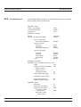
Table of Contents
Chapter 1 - General Information
1-1
Scope of This Manual . . . . . . . . . . . . . . . . . . . . . . . . . . 1-1
1-2
Introduction . . . . . . . . . . . . . . . . . . . . . . . . . . . . . . . . 1-1
1-3
Related Manuals . . . . . . . . . . . . . . . . . . . . . . . . . . . . . 1-1
1-4
Identification Number . . . . . . . . . . . . . . . . . . . . . . . . . . . 1-2
1-5
Power Meter Models, Options, and Accessories . . . . . . . . . . . . . 1-2
1-6
Sensors. . . . . . . . . . . . . . . . . . . . . . . . . . . . . . . . 1-3/1-4
Chapter 2 - Installation
2-1
Introduction . . . . . . . . . . . . . . . . . . . . . . . . . . . . . . . . 2-1
2-2
Initial Inspection . . . . . . . . . . . . . . . . . . . . . . . . . . . . . 2-1
2-3
Sensor Handling . . . . . . . . . . . . . . . . . . . . . . . . . . . . . 2-1
2-4
Power Requirements . . . . . . . . . . . . . . . . . . . . . . . . . . . 2-1
2-5
Environmental Requirements. . . . . . . . . . . . . . . . . . . . . . . 2-3
2-6
Rack Mounting . . . . . . . . . . . . . . . . . . . . . . . . . . . . . . 2-3
2-7
Battery Charging, Removal and Replacement . . . . . . . . . . . . . . 2-9
2-8
Storage and Shipment . . . . . . . . . . . . . . . . . . . . . . . . . 2-11
Chapter 3 - Connections
3-1
Introduction . . . . . . . . . . . . . . . . . . . . . . . . . . . . . . . . 3-1
3-2
Front Panel Connectors . . . . . . . . . . . . . . . . . . . . . . . . . 3-1
3-3
Rear Panel Connectors. . . . . . . . . . . . . . . . . . . . . . . . . . 3-2
Chapter 4 - Front Panel Operation
4-1
Introduction . . . . . . . . . . . . . . . . . . . . . . . . . . . . . . . . 4-1
4-2
Front Panel Controls . . . . . . . . . . . . . . . . . . . . . . . . . . . 4-1
4-3
Power-on Procedure . . . . . . . . . . . . . . . . . . . . . . . . . . . 4-3
4-4
Sensor Menu4-5
4-5
Channel Menu. . . . . . . . . . . . . . . . . . . . . . . . . . . . . . 4-12
4-6
Trigger Menu 4-15
4-7
System Menu . . . . . . . . . . . . . . . . . . . . . . . . . . . . . . 4-20
4-8
Cal/Zero Menu . . . . . . . . . . . . . . . . . . . . . . . . . . . . . 4-34
ML2430A OM
i
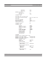
Chapter 5 - Procedures
5-1
Introduction . . . . . . . . . . . . . . . . . . . . . . . . . . . . . . . . 5-1
5-2
Power Measurement . . . . . . . . . . . . . . . . . . . . . . . . . . . 5-1
5-3
Zeroing the Sensor . . . . . . . . . . . . . . . . . . . . . . . . . . . . 5-1
5-4
Sensor Calibration . . . . . . . . . . . . . . . . . . . . . . . . . . . . 5-2
5-5
Sensor Zero/Cal . . . . . . . . . . . . . . . . . . . . . . . . . . . . . 5-3
5-6
Performance Verification . . . . . . . . . . . . . . . . . . . . . . . . . 5-4
5-7
Printer Connection . . . . . . . . . . . . . . . . . . . . . . . . . . . . 5-4
5-8
GPIB Remote Operation . . . . . . . . . . . . . . . . . . . . . . . . . 5-4
5-9
Serial Remote Operation . . . . . . . . . . . . . . . . . . . . . . . . . 5-5
5-10
RS232 Modem Support . . . . . . . . . . . . . . . . . . . . . . . . . 5-6
5-11
Profile Operation Mode . . . . . . . . . . . . . . . . . . . . . . . . 5-11
5-12
Source Sweep Mode. . . . . . . . . . . . . . . . . . . . . . . . . . 5-17
5-13
Power vs. Time Mode . . . . . . . . . . . . . . . . . . . . . . . . . 5-19
5-14
User Cal Factors . . . . . . . . . . . . . . . . . . . . . . . . . . . . 5-19
5-15
Optimizing Readings. . . . . . . . . . . . . . . . . . . . . . . . . . 5-21
5-16
Operator Maintenance . . . . . . . . . . . . . . . . . . . . . . . . . 5-25
Chapter 6 - GPIB Operation
ii
6-1
Introduction . . . . . . . . . . . . . . . . . . . . . . . . . . . . . . . . 6-1
6-2
Typographic Conventions . . . . . . . . . . . . . . . . . . . . . . . . . 6-1
6-3
Data I/O Formats . . . . . . . . . . . . . . . . . . . . . . . . . . . . . 6-1
6-4
Query Commands . . . . . . . . . . . . . . . . . . . . . . . . . . . . 6-4
6-5
GPIB PC Card Setup . . . . . . . . . . . . . . . . . . . . . . . . . . . 6-5
6-6
Using 488.1 GPIB . . . . . . . . . . . . . . . . . . . . . . . . . . . . 6-6
6-7
Using 488.2 GPIB . . . . . . . . . . . . . . . . . . . . . . . . . . . . 6-7
6-8
Service Request Status (SRQ) . . . . . . . . . . . . . . . . . . . . . . 6-9
6-9
Functional Groups. . . . . . . . . . . . . . . . . . . . . . . . . . . . 6-10
6-10
ML24XXA Native Commands . . . . . . . . . . . . . . . . . . . . . 6-12
6-11
GPIB Emulation Modes . . . . . . . . . . . . . . . . . . . . . . . . 6-84
6-12
ML4803A Emulation Commands . . . . . . . . . . . . . . . . . . . 6-85
6-13
HP 436A Emulation Commands . . . . . . . . . . . . . . . . . . . . 6-96
6-14
HP 437B Emulation Commands . . . . . . . . . . . . . . . . . . . 6-101
6-15
HP 438A Emulation Commands . . . . . . . . . . . . . . . . . . . 6-118
6-16
Programming Examples . . . . . . . . . . . . . . . . . . . . . . . 6-129
ML2430A OM
Appendix A - Specifications
A-1
Introduction A-1
A-2
System Specifications . . . . . . . . . . . . . . . . . . . . . . . . . . A-1
A-3
System Defaults . . . . . . . . . . . . . . . . . . . . . . . . . . . . . A-6
A-4
System Error Messages . . . . . . . . . . . . . . . . . . . . . . . . A-11
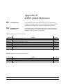
Appendix B - GPIB Quick Reference
B-1
Introduction B-1
B-2
ML24XXA Quick Reference . . . . . . . . . . . . . . . . . . . . . . . B-1
B-3
ML4803A Quick Reference . . . . . . . . . . . . . . . . . . . . . . . B-9
B-4
HP 436A Quick Reference . . . . . . . . . . . . . . . . . . . . . . . B-10
B-5
HP 437B Quick Reference . . . . . . . . . . . . . . . . . . . . . . . B-11
B-6
HP 438A Quick Reference . . . . . . . . . . . . . . . . . . . . . . . B-14
B-7
HP-IB Support . . . . . . . . . . . . . . . . . . . . . . . . . . . . . B-16
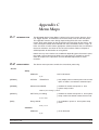
Appendix C - Menu Maps
C-1
Introduction C-1
C-2
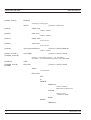
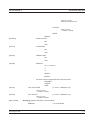
Sensor Menu . . . . . . . . . . . . . . . . . . . . . . . . . . . . . . C-1
C-3
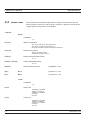
Channel Menu . . . . . . . . . . . . . . . . . . . . . . . . . . . . . . C-6
C-4
Trigger Menu. . . . . . . . . . . . . . . . . . . . . . . . . . . . . . . C-8
C-5
System Menu . . . . . . . . . . . . . . . . . . . . . . . . . . . . . . C-9
C-6
Cal/Zero Menu . . . . . . . . . . . . . . . . . . . . . . . . . . . . . C-15
Index
ML2430A OM
iii/iv
Chapter 1
General Information
1-1
SCOPE OF THIS
MANUAL
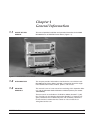
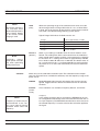
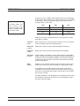
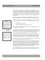
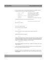
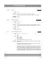
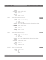
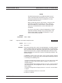
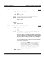
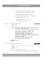
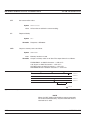
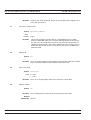
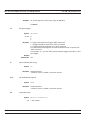
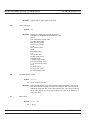
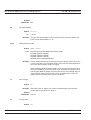
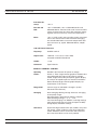
This manual provides installation and operation information for the Model
ML2430A Series of ANRITSU Power Meters (Figure 1-1).
Figure 1-1. ML2430A Series Power Meters
1-2
1-3
INTRODUCTION
This chapter provides information to familiarize the user with the basic
ML2430A Series Power Meter. Included is information about the equipment identification number, models, options, and sensors.
RELATED
MANUALS
This manual is one of a two manual set consisting of this Operation Manual, and the ML2430A Series Maintenance Manual (Anritsu part number
10585-00003).
These manuals are available on CD ROM as Adobe Acrobat™ (*.pdf)
files. The files can be viewed using Acrobat Reader™, a freeware program provided on the CD ROM. For price and availability, contact the
nearest Anritsu Customer Service Center or visit our web site at:
www.global.anritsu.com.
ML2430A OM
1-1
IDENTIFICATION NUMBER
1-4
1-5
GENERAL
INFORMATION
IDENTIFICATION
NUMBER
The ML2430A Series ID number is affixed to the rear panel (see Figure
3-2). Please use the complete ID number when ordering parts or corresponding with the Anritsu Customer Service department.
POWER METER
MODELS, OPTIONS, AND
ACCESSORIES
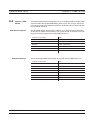
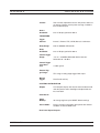
The ML2430A Series Power Meter is available with either one or two sensor inputs, and is delivered with a 1.5m sensor cable (ML2400A-20) for
each input. Model numbers, options, and accessories are listed below.
Models
Model No.
ML2437A
ML2438A
Number of Sensor Channels
Single Channel
Dual Channel
Options
Model No.
ML2400A-01
ML2400A-03
ML2400A-05
Option
Rack Mount, single unit
Rack Mount, side-by-side
Front Bail Handle
(Options -01 thru -05 are mutually exclusive.)
ML2400A-06
ML2400A-07
ML2400A-08
ML2400A-09
Rear Panel Mounted Input A
Rear Panel Mounted Input A & Reference
Rear Panel Mounted Inputs A, B, & Reference
Rear Panel Mounted Inputs A & B
(Options -06 thru -09 are mutually exclusive.)
ML2400A-11
ML2400A-12
3000 mA-h, NiMH Battery
Front Panel Cover
(Can not be used with rack mounted units.)
1-2
ML2400A-13
External Battery Charger
Accessories
Part No.
760-206
D41310
ML2419A
B41323
MA2418A
Item
Hard Sided Transit Case
Soft Sided Carry Case with shoulder strap
Range Calibrator
Serial Interface Cable
50 MHz, 0 dBm Reference Source
ML2430A OM
GENERAL
INFORMATION
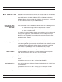
1-6
SENSORS
SENSORS
The following sensors, sensor options, and sensor accessories are available for use with the ML2430A Series Power Meters:
Power Sensors (–70 to + 20 dBm)
Range
Model No.
MA2468A
10 MHz – 6 GHz
MA2469B
10 MHz – 18 GHz
(–60 to +20 dBm, nominal bw 1.2 MHz)
MA2472A
10 MHz – 18 GHz
MA2473A
10 MHz – 32 GHz
MA2474A
10 MHz – 40 GHz
MA2475A
10 MHz – 50 GHz
Thermal Sensors (–30 to + 20 dBm)
Range
Model No.
MA2421A
100 KHz to 18 GHz
MA2422A/B
10 MHz – 18 GHz
MA2423A/B
10 MHz – 32 GHz
MA2424A/B
10 MHz – 40 GHz
MA2425A/B
10 MHz – 50 GHz
High Accuracy Sensors (–64 to +20 dBm)
Range
Model No.
MA2442A
10 MHz – 18 GHz
MA2444A
10 MHz – 40 GHz
MA2445A
10 MHz – 50 GHz
Universal Power Sensor
Range
Model No.
MA2481A
10 MHz – 6 GHz
MA2480/01
Add Fast CW
Sensor Options
MA2400A-10
ML2430A OM
Extra Cal Factor Freq., 0.01 – 40 GHz
1-3
SENSORS
NOTE
The use of sensor cables greater than 10
meters in length is not
recommended when
measuring pulses of
less than 10 ms.
1-4
GENERAL
INFORMATION
Sensor Accessories
ML2400A-20
ML2400A-21
ML2400A-22
ML2400A-23
1.5m Sensor Cable
0.3m Sensor Cable
3m Sensor Cable
5m Sensor Cable
ML2400A-24
ML2400A-25
ML2400A-26
ML2400A-27
ML2400A-29
ML2400A-30
ML2400A-33
MA2499B
MA2497A
1N75C
1N50C
1K50A
1K50B
42N75-20
42N50-20
42N50-30
42KC-20
10m Sensor Cable
30m Sensor Cable
50m Sensor Cable
100m Sensor Cable
Bulkhead Adapter
Extra Operation Manual ML2437/38A
Printer
Anritsu Sensor Adapter
HP Sensor Adapter
5W Limiter, 0.01 – 3 GHz, Nm-f, 75W
5W Limiter, 0.01 – 18 GHz, Nm-f, 50W
5W Limiter, 0.01 – 20 GHz, Km-f, 50W
3W Limiter, 0.01 – 26 GHz, Km-f, 50W
5 Watt Attenuator, Nm-f, 75W
5 Watt Attenuator, Nm-f, 50W
50 Watt Attenuator, Nm-f, 50W
5 Watt Attenuator, Km-f, 50W
ML2430A OM
Chapter 2
Installation
2-1
2-2
INTRODUCTION
This chapter provides information for the initial inspection and preparation
for use of the ML2430A Series Power Meter. Shipping and storage information is also included.
INITIAL
INSPECTION
Inspect the shipping container for damage. If the container or cushioning
material is damaged, retain until the contents of the shipment have been
checked against the packing list and the instrument has been checked for
mechanical and electrical operation.
If the power meter is damaged mechanically, notify your local sales representative or Anritsu Customer Service Center. If either the shipping container is damaged or the cushioning material shows signs of stress, notify
the carrier as well as Anritsu. Retain the shipping materials for the carrier's inspection.
2-3
2-4
SENSOR
HANDLING
The sensors are enclosed in a polycarbonate case to help prevent damage. The sensor connectors, however, are exposed and are a critical part
of the microwave instrument. Refer to the MA24XXA Series Power Sensor
manual (10585-00004) for detailed information on proper connector care.
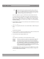
POWER
REQUIREMENTS
The ML2430A Series Power Meter can be operated from either AC line
power, external DC power, or from the optional internal battery. The
ML2430A Series Power Meter is intended as an Installation (Overvoltage)
Category II, Insulation Category I device.
At power-on, the power meter will perform a brief power-on self test
(POST). If a POST error occurs, information and available options will be
displayed on the screen (See Chapter 4, page 4-3). If the POST is successful, the instrument will load the last used configuration, unless Secure
mode has been selected (see Chapter 4, page 4-34, or Chapter 6, page
6-68).
ML2430A OM
AC Line Power
The ML2430A Series Power Meter can operate on AC
input power of 85-264V, 50-440 Hz, 40 VA maximum.
The Power Meter automatically configures itself for the
voltage applied. The AC line input is protected by an
internal fuse.
DC Power
The ML2430A Series Power Meter can also operate
from a nominal external 12-24 VDC input in the absence of AC line power. DC line power is protected by
2-1
POWER REQUIREMENTS
INSTALLATION
a fuse mounted inside the unit, on the main board. A
grounding terminal is provided on the rear panel to
ground the unit during operation from a DC supply.
Battery Power
The ML2430A Series Power Meter can be operated
using the optional internal battery pack. During battery
operation, an icon will be displayed on measurement
screens indicating the state of charge. When the
remaining capacity reaches less than 10%, the icon
will flash, indicating that charging will soon be required.
When running from battery power, an estimate of
typical-use running time remaining can be viewed
using the System menu (see Chapter 4, Front Panel
Operation). Note that, due to power consumption considerations, GPIB and serial remote operation are not
available when the power meter is running from the
battery.
The AUTO POWER OFF feature is also available
through the System menu, and can be used to
automatically switch the unit to standby after a specified period of inactivity to save battery power. The
timer can be set for 10 to 240 minutes, and any key
press will restart the timer. This same feature will automatically switch the unit to standby when the battery is
fully discharged in order to minimize the risk of overdischarge.
NOTE
The ML2430A Series Power Meter uses a
high-capacity Ni-MH battery (option ML2400A11). Over-discharge can result in a permanent
loss of battery capacity of as much as 20%. If
the unit is to be stored for an extended period
(longer than one week), remove the optional
battery pack so as to preclude over-discharge.
For optimum battery life, store the battery pack
at –20 to +50° C (–4 to +122° F) for short periods and
–20 to +35° C (–4 to +95° F) for long term storage.
The ML2430A Series Power Meter will operate from
AC or DC main power with this battery removed. This
battery is not used for the retention of nonvolatile
memory functions. Refer to Section 2-7, Battery
Charging, Removal and Replacement, for further information.
2-2
ML2430A OM
INSTALLATION
2-5
ENVIRONMENTAL
REQUIREMENTS
ENVIRONMENTAL REQUIREMENTS
Fuses
The ML2430A Series Power Meter AC and DC input
lines are protected by internally mounted fuses. These
fuses should only be changed by qualified service personnel. Replace only with fuses of the same type and
rating (AC fuse is 2A, 250V, slow-blow; DC fuse is 3A,
125V, slow-blow).
Grounding
The ML2430A Series Power Meter must be properly
grounded. Failure to ground the instrument could be
hazardous to operating personnel. The meter is supplied with a three-conductor power cord. The instrument is properly grounded during AC line operation
when the plug is connected to a properly installed
three-prong receptacle. A grounding terminal is provided on the rear panel to ground the unit during operation from a DC supply.
The ML2430A Series Power Meter is designed to operate within the temperature range of 0 to 50° C (32 to 122° F) with a maximum humidity of
90% at 40° C (104° F), non-condensing. Full accuracy is specified at 5 to
35° C (23 to 95° F).
Although not recommended, operation in temperatures to –20° C
(–4° F) is possible. At these temperatures, however, the liquid crystal display may exhibit excessively slow response. The soft sided carry case
(part number D41310) and optional front panel cover (option ML2400A12) can be used to help retain internally generated heat and may improve
response.
2-6
RACK MOUNTING
The ML2430A Series Power Meter can be ordered with rack mounting
hardware that allows the unit to be mounted into a standard 19-inch
equipment rack. There are two rack mount option kits available:
q
The ML2400A-01 Rack Mount option allows the installation of a single ML2430A in either the left or right side rack position.
q The ML2400A-03 Rack Mount option allows side-by-side mounting
of two ML2430A Power Meters.
The Power Meter itself must be ordered from the factory as a rack
mount-ready unit. As such, it will be fitted with rack mount top and bottom
cases. These cases have extra mounting holes so that the rack mount kits
can be installed. Instructions for installing the rack mount kits follow.
ML2400A-01 Rack
Mount Installation
ML2430A OM
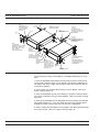
This section describes the assembly procedure for fitting a single ML2430A
Power Meter (PM) unit into an instrument rack. The PM must be fitted with rack
mount top and bottom covers before the rack mount kit can be fitted. The procedure involves fitting the support bracket to the PM. The PM can then be loaded
and secured in the rack position desired.
2-3
RACK MOUNTING
INSTALLATION
The required parts and tools are listed below:
Quantity
(each)
Description
Anritsu Part
Number
2
HANDLE, PULL, CHASSIS, PLASTIC, HARDWARE
783-1055
4
SPEED NUT
790-319
8
6-32, SST, WASHER, FLAT
900-345
4
M4, 8.00 MM, PHH, SCREW, FLAT HEAD
900-795
4
DECORATIVE SCREW
900-821
8
M3X8, POS, SST, PATCHLOCK, SCREW, METRIC,
PAN HEAD
905-68
M3X5, POS, SST, PATCHLOCK, SCREW, METRIC,
PAN HEAD
905-72
6
SNAP RIVET, PLASTIC
788-575
1
RACK MOUNT, SIDE, BRACKET
C37276
1
REAR SUPPORT, BRACKET, RACK MOUNT
C41449
1
RACK MOUNT, SUPPORT, BRACKET
D41473
1
BRACKET SUPPORT, BASE PANEL
49361
1
FRONT FACE PLATE
49362
1
POWER METER FITTED WITH RACK MOUNT TOP
AND BOTTOM COVERS
6
Max. Torque
Setting
.4lbf.in
[45cN m]
.4lbf.in
[45cN m]
ML2430A
Table 2-1 ML2430A-01 Rack Mount Kit Parts List
Tools Required:
Assembly Procedure
Small Phillips screw driver
Large Phillips screw driver
Small Phillips torque screw driver 10cNm to 120cNm
Assembly drawing “ML2400A/01 RACK MOUNTED LEFT
OR RIGHT OPTION”
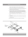
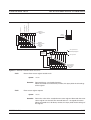
1. Confirm the correct tools are available and the parts listed above are present. Refer to diagram on page 2-5 throughout this procedure.
2. Fit the two handles 783-1055 to front plate 49362 and the front rack bracket
C37376 using 4 screws 900-795.
3. Lay the large support bracket D41473 next to the Power Meter as per the assembly drawing. Note if the PM needs to be mounted on the left hand side of the rack,
simply lay the bracket on the PM’s right side. i.e. a mirror image of the assembly
drawing.
4.
2-4
ML2430A OM
INSTALLATION
RACK MOUNTING
Locate the support bracket on the four PM case pillars. Secure with 4 screws
905-68 and 4 washers 900-345. (See max. torque settings page 2-4.)
5. Locate the front rack mounting bracket C37276 at the front of the PM on the other
side to the large support bracket with two screws 905-68 and two washers
900-345. (See max. torque settings page 2-4).
6. Locate the rear bracket C41449 at the back of the PM on the other side to the
large support bracket with two screws 905-68 and two washers 900-345. See
maximum torque settings above.Locate the rear bracket C41449 at the back of
the PM on the other side to the large support bracket with two screws 905-68 and
two washers 900-345. (See max. torque settings page 2-4).
7. Fit the front plate 49362 with 6 screws 905-72. (See max. torque settings page
2-4).
8. Position the base panel 49361 as shown in the drawing, and secure with 6 snap
rivets 788-575.
9. Fit the four speed nut 790-319 to the rack in the correct place to allow mounting
of the PM in the rack.
10. Slide the PM into the rack and secure with 4 decorative screws 900-821.
788-575
X6
SNAP RIVET
PRESS DOWN CENTER
PIN USING A FLAT EDGE
041473
SUPPORT
BRACKET
49361
BASE PANEL
905-68
X8
905-72
X6
SCREW
NOTE:
FIT COMPLETED
ASSEMBLY TO RACK USING
DECORATIVE SCREW 900-821
X4 AND SPEED NUT 790-319
X4 IN 4 CORNER
POSITIONS AS SHOWN
900-345
X8
900-795
X4
C41449
RACKMOUNT
BRACKET
REAR SUPPORT
49362
FRONT PLATE
783-1055
HANDLE
X2
C37276
RACKMOUNT
SIDE BRACKET
ML2430A OM
2-5
RACK MOUNTING
INSTALLATION
ML2400A-03 Rack
Mount Installation
This section describes the assembly procedure for fitting two ML2430A Power
Meters (PM) into a instrument rack. The PM’s must be fitted with rack mount top
and bottom covers for the rack mount kit to be fitted. The procedure involves fitting support brackets, two front handles, and two rear support brackets, one to
each PM. The two PM,s which are locked together can then be loaded and secured in the rack position desired. This assembly procedure also provides assembly instructions for fitting a ML2430A to a HP34401A Multimeter and a MF2412A
Microwave Frequency Counter.
The required parts and tools are listed below:
Quantity
(each)
Description
Anritsu Part
Number
2
HANDLE, PULL, CHASSIS, PLASTIC,
HARDWARE
783-1055
4
SPEED NUT
790-319
16
WASHER, 6-32UNC, OVERSIZE
900-345
4
M4, 8.00 MM, PHH, SCREW, FLAT HEAD
900-795
4
DECORATIVE SCREW
900-821
16
M3X8, POS, SST, PATCHLOCK, SCREW, METRIC, PAN HEAD
905-68
4
M3X6, POS, SST, PATCHLOCK, SCREW, METRIC, FLAT HEAD
905-69
4
WASHER, M4 SPLIT.
900-807
2
M4X12MM, SCREW, PAN HD
900-806
2
M3.5X8MM, SCREW, PAN HD
905-103
4
M4X10MM, SCREW, FLT HD
905-63
1
RACK MOUNT, SIDE BRACKET
49415
1
RACK MOUNT, CENTRE, FRT, BRACKET
49413
1
SPACER PLATE
49439
1
RACK MOUNT, CENTER, FRONT, BRACKET
C37275
2
RACK MOUNT, SIDE, BRACKET
C37276
1
RACK MOUNT, CENTER, BRACKET
C37277
1
RACK MOUNT, CENTER, BRACKET
C37279
2
REAR SUPPORT, BRACKET, RACK MOUNT
C41449
2
POWER METER FITTED WITH RACK MOUNT
TOP
Max. Torque
Setting
.4lbf.in
[45cN m]
Table 2-2 ML2430A-03 Rack Mount Kit Parts List
2-6
ML2430A OM
INSTALLATION
RACK MOUNTING
Tools Required:
Assembly Procedure
1 Small Phillips screw driver
1 Large Phillips screw driver
1 Small Phillips torque screw driver 10cNm to 120cNm.
1 Assembly drawing “ML2400/03 SIDE BY SIDE OPTION”
1. Confirm the correct tools are available and the parts listed above are present. Refer to diagram on page 2-8 throughout this procedure.
2. On the two sides of the power meter to be joined together, fit the two rear brackets 49413, C37279, and two front brackets C37275, C37277 using 8 screws
905-68 and 8 washers 900-345. (See max. torque settings page 2-6).
3. Slide the two PM units together and secure using 4 counter sink screws 905-69.
4. Fit the two handles 783-1055 to the front rack brackets using 4 screws 900-795.
5. Locate the two front rack brackets C37276 and 49415 at the front of each of the
PM’s, one on each side with four screws 905-68 and four washers 900-345. See
max, torque setting above.
6. Locate the two rear rack brackets C41449 at the back of each of the PM’s one on
each side with four screws 905-68 and four washers 900-345. (See max. torque
settings page 2-6).
7. Fit the four speed nuts 790-319 to the rack in the correct place to allow mounting
of the two PM’s in the rack.
8. Slide the instruments into the rack and secure with the four decorative screws
(900-821) provided.
ML2430A OM
2-7
RACK MOUNTING
INSTALLATION
49415
RACKMOUNT SIDE
BRACKET (MULTI-FIT).
USE THIS BRACKET
WHEN FITTING A
HP34401A
905-63
x2
905-68
x 16
900-345
x 16
C37279
RACKMOUNT BRACKET
CENTER INNER REAR
49413
RACKMOUNT BRACKET
CENTER REAR
900-795
x4
900-807 X2
900-806 X2
USE THESE FIXINGS
WHEN FITTING A MF2412A
COUNTER TO A ML2430A
POWER METER
900-103 X2
900-807 X2
USE THESE FIXINGS WHEN
FITTING A HP34401A
MULTIMETER TO A ML2430A
POWER METER
NOTE:
FIT COMPLETED
ASSEMBLY TO RACK USING
DECORATIVE SCREW 900-821
X4 AND SPEED NUT 790-319
X4 IN 4 CORNER
POSITIONS AS SHOWN
C37275
RACKMOUNT
BRACKET
CENTER FRONT
905-69
x4
905-63 x 4
USE THESE FIXINGS WHEN
FITTING A HP 34401A TO A
ML2430A OR MF2412A
C37277
RACKMOUNT
BRACKET
CENTER INNER
FRONT
49439 X2
SPACER PLATE
USE ON A HP 34401A
ONLY, IN 2 POSITIONS
WHEN FITTING TO A
ML2430A OR MF2412A.
USE ALSO WITH SIDE
BRACKET 49415
C41449
RACKMOUNT BRACKET
REAR SUPPORT
X2
USE THESE BRACKETS
WHEN FITTING A ML2430A
TO ANOTHER ML2430A
POWER METER.
783-1055
HANDLE
X2
C37276
RACKMOUNT SIDE
BRACKET
The procedure for fitting a ML2430A to a HP34401A Multimeter is as follows:
1. Fit to the ML2430A Power Meter front brackets C37276, C37275 and
rear bracket C41449 using 6 screws 905-68 and 6 washers 900-345. Do
not tighten fully at this stage, only enough to allow the bracket to slide to
its maximum position.
2. Fit the center rear bracket 49413 using 2 screws 905-63. (See max.
torque settings page 2-6).
3. Fit to the HP34401A spacer plate 49439 in 2 positions with front brackets C37277 and 49415 using 4 screws 905-63. (See max. torque settings
page 2-6).
4. Offer up the HP34401A to the ML2430A unit ensuring the front bracket
fixing holes ofboth units are in line. Slide the center rear bracket 49413
forward till it makes contact with the rear face of the HP34401A.
5. Gently remove the HP34401A unit and tighten the 49413 bracket fixings
in its new position. (See max. torque settings page 2-6).
2-8
ML2430A OM
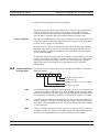
BATTERY CHARGING, REMOVAL AND REPLACEMENT
2-7
BATTERY
CHARGING,
REMOVAL AND
REPLACEMENT
INSTALLATION
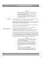
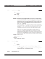
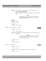
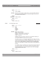
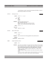
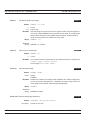
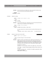
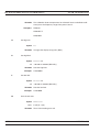
The optional ML2430A Series Power Meter battery is a 12 Volt, 3000
mA-h nickel-metal hydride (Ni-MH) multi-cell pack, located in a compartment on the bottom of the housing. The compartment cover is secured by
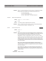
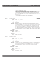
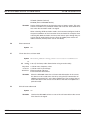
fractional turn fasteners, as shown in Figure 2-1. Rotate the fasteners approximately ¼-turn counterclockwise to release the cover.
NOTE
ML2430A
BATTERY
COVER
OPEN
BATTERY
OPEN
BATTERY
COVER
FASTENERS
NOTE: Do not lubricate the battery cover fasteners.
Figure 2-1. Model ML2430A Series Battery Compartment
The battery is shipped with a partial charge only, and
should be fully charged before use.
The battery can be completely charged in about two hours with the power
meter in standby mode by selecting CHARGE from the System menu
(page 4-30). This selection is available only when the instrument is being
powered by AC line power or external DC power greater than 21 volts.
Note that the instrument will shut down during the charging cycle, and restart automatically when the charging is completed. A series of 10 beeps
signals completion of the charge cycle.
The external battery charger (option ML2400A-13) can completely charge
the battery in 2.5 hours.
ML2430A OM
2-9
INSTALLATION
BATTERY CHARGING, REMOVAL AND REPLACEMENT
CAUTION
• To avoid excessive heat build
up, always remove the
ML2430A from the optional
soft sided carrying case
(D41310) before selecting fast
charging.
For optimal battery life, the battery should be fully discharged before recharging. Repeated partial charge/discharge cycles can result in a loss of
battery capacity, recoverable by applying several “conditioning” (full
charge/discharge) cycles. If the power meter determines that a battery
conditioning cycle is required, a message stating this requirement will be
displayed on the front panel, and will remain until the battery is fully conditioned or replaced. A number of complete conditioning cycles may be necessary to fully condition a battery.
The ideal battery temperature ranges are:
q Discharging: –20 to +50° C (–4 to +122° F)
q Charging:
+10 to +45° C (+50 to +113° F)
Note that charging will be inhibited if the temperature falls outside these
limits.
CAUTION
• The ML2430A battery pack
can leak, explode, or catch on
fire if it is opened, disassembled, or exposed to fire or
very high temperatures. No
attempt should be made to
open, repair, or modify the
battery package.
To remove the battery, first disconnect any AC or DC input line power.
Open the battery compartment as illustrated and remove the battery. Replace the battery only with an identical battery or an equivalent as
recommended by an Anritsu Service Center. Ensure that the battery is
correctly connected and that the battery compartment cover is securely
fastened.
Note that the battery is an optional component that is not used for the retention of nonvolatile memory functions, and is not required for the Power
Meter to operate from either AC or DC line sources. Serial and GPIB remote operation, however, are not available when the power meter is
running from battery power.
• When a battery pack has
reached the end of its functional life, it should be returned to the nearest Anritsu
Service Center for proper recycling or disposal. Do not
treat a used battery as normal
waste.
2-10
ML2430A OM
INSTALLATION
2-8
STORAGE AND SHIPMENT
STORAGE AND
SHIPMENT
The following paragraphs describe preparing the power meter for storage and
shipment.
Preparation for
Storage
Preparing the power meter for storage consists of cleaning the unit and packing it
with moisture-absorbing desiccant crystals. Whenever the unit is to be stored for
an extended period (longer than one week), it is advisable to remove the optional
battery pack. Refer to Section 2-7, “Battery Charging, Removal and Replacement,” for instructions.
Environmental
Requirements
Store the unit in a temperature controlled environment that is maintained between –40 and +70° C
(–40 to +156° F), with a maximum humidity of 90% at 40° C (104° F), noncondensing. For optimum battery life, store the battery pack at –20 to +50° C (–4
to +122° F) for short periods and –20 to +35° C (–4 to +95° F) for long term
storage.
Preparation for
Shipment
To provide maximum protection against damage in transit, the power meter
should be repackaged in the original shipping container. If this container is no
longer available and the power meter is being returned to Anritsu for repair, advise Anritsu Customer Service Center; they will send a new shipping container
free of charge. In the event neither of these two options is possible, follow the
packaging instructions below.
Use a
Suitable
Container
Obtain a corrugated cardboard carton with a 275-pound test
strength. This carton should have inside dimensions of no less than
six inches larger than the instrument dimensions to allow for
cushioning.
Protect the
Instrument
Wrap the instrument to protect the finish.
Cushion the
Instrument
Cushion the instrument on all sides by tightly packing dunnage or
urethane foam between the carton and the instrument. Provide at
least three inches of dunnage on all sides.
Seal the
Container
Seal the carton using either shipping tape or an industrial stapler.
Address the ConIf the instrument is being returned to Anritsu for service, mark the
tainer
address of the appropriate Anritsu service center (Table 2-1), the
Return Materials Authorization (RMA) number, and your return address on the carton in a prominent location.
ML2430A OM
2-11
STORAGE AND SHIPMENT
INSTALLATION
Table 2-3. ANRITSU Service Centers
UNITED STATES
FRANCE
KOREA
ANRITSU SALES COMPANY
685 Jarvis Drive
Morgan Hill, CA 95037-2809
Telephone: (408) 776-8300
FAX: (408) 776-1744
ANRITSU S.A
9 Avenue du Quebec
Zone de Courtaboeuf
91951 Les Ulis Cedex
Telephone: 016-44-66-546
FAX: 016-44-61-065
ANRITSU KOREA
#901 Daeo building 26-5
Yeoido Dong, Youngdeungpo
Seoul, Korea 150010
Telephone: 02-782-7156
FAX: 02-782-4590
ANRITSU SALES COMPANY
10 Kingsbridge Road
Fairfield, NJ 07004
Telephone: (201) 227-8999
FAX: (201) 575-0092
GERMANY
SINGAPORE
ANRITSU GmbH
Grafenberger Allee 54-56
D-40237 Dusseldorf, Germany
Telephone: 0211-67-97-60
FAX: 0211-68-33-53
ANRITSU (SINGAPORE)
PTE LTD
3 Shenton Way
#24-03 Shenton House
Singapore 068805
Telephone: 226-5206
FAX: 226-5207
AUSTRALIA
ANRITSU PTY. LTD.
Unit 3, 170 Foster Road
Mt Waverley, VIC 3149
Australia
Telephone: 03--9558--8177
FAX: 03--9558--8255
BRAZIL
ANRITSU ELETRONICA LTD
Praia de Botafogo 440, Sala 2401
CEP 22250-040
Rio de Janeiro, RJ, Brasil
Telephone: 021-527-6922
FAX: 021-53-71-456
CANADA
ANRITSU INSTRUMENTS LTD.
215 Stafford Road, Unit 102
Nepean, Ontario K2H 9C1
Telephone: (613) 828-4090
FAX: (613) 828-5400
CHINA
ANRITSU BEIJING SERVICE CENTER
416W Beijing Fortune Building
5 Dong San Huan Bei Lu
Chao Yang Qu, Beijing 1000004, China
Telephone: 011861065909237
FAX: 011861065909236
2-12/2-12
INDIA
MEERA AGENCIES (P) LTD.
Head Office
A-23 Hauz Khas
New Delhi 110 016
Telephone: 011-685-3959
FAX: 011-686-6720
ISRAEL
TECH-CENT, LTD
Haarad Street No. 7
Ramat Haahayal
Tel Aviv 69701
Telephone: 03-64-78-563
FAX: 03-64-78-334
ITALY
ANRITSU Sp.A
Roma Office
Via E. Vittorini, 129
00144 Roma EUR
Telephone: 06-50-22-666
FAX: 06-50-22-4252
JAPAN
ANRITSU CORPORATION
1800 Onna Atsugi-shi
Kanagawa-Prf. 243 Japan
Telephone: 0462-23-1111
FAX: 0462-25-8379
SOUTH AFRICA
ETESCSA
1st Floor Montrose Place
Waterfall Park
Becker Road
Midrand, South Africa
Telephone: 011-315-1366
FAX: 011-315-2175
SWEDEN
ANRITSU AB
Box 247
S-127 25 Skarholmen
Telephone: 08-74-05-840
FAX: 08-71-09-960
TAIWAN
ANRITSU CO., LTD.
8F, No. 96, Section 3
Chien Kuo N. Road
Taipei, Taiwan, R.O.C.
Telephone: 02-515-6050
FAX: 02-509-5519
UNITED KINGDOM
ANRITSU EUROPE LTD.
200 Capability Green
Luton, Bedfordshire
LU1 3LU, England
Telephone: 015-82-41-88-53
FAX: 015-82-31-303
ML2430A
Chapter 3
Connections
3-1
3-2
INTRODUCTION
This chapter describes physical connections to the power meter on both
the front and rear panels.
FRONT PANEL
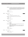
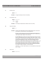
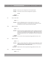
CONNECTORS
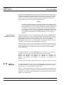
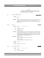
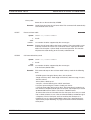
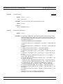
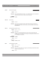
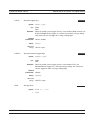
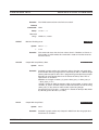
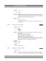
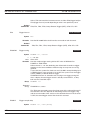
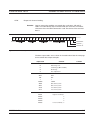
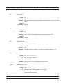
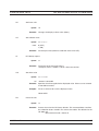
The front panel connectors are illustrated in Figure 3-1. Detailed descriptions of each connector follow.
Calibrator
Connector
Sensor A
Connector
Sensor B
Connector
(ML2438A only)
Figure 3-1. Model ML2430A Series Power Meter Front Panel Connectors
Calibrator
0.0 dBm Reference
ML2430A OM
This connector is a precision female N-Type, 50 Ohm connector that provides a
precision, traceable 0.0 dBm, 50 MHz reference signal for absolute calibration of
the sensors. The calibration signal can be turned on or off through the Cal/Zero
menus (see Chapter 4, Front Panel Operation). Use only compatible 50 Ohm NType connectors.
3-1
REAR PANEL CONNECTORS
CONNECTIONS
An optional rear panel Calibrator connector is offered as an alternative (see Figure 3-2). If the rear panel connector option is installed, the front panel connector
is not installed. Refer to Chapter 5, Procedures, for information on using the Calibrator output.
Sensor A
Connector
This connector is a 12-pin circular precision connector to be used in conjunction
with power sensor cables. An optional rear panel Channel A connector is offered
as an alternative (see Figure 3-2). If the rear panel connector option is installed,
the front panel connector is not installed.
Sensor B
Connector
(ML2438A only)
This connector is a 12-pin circular precision connector to be used in conjunction
with power sensor cables. An optional rear panel Channel B connector is offered
as an alternative (see Figure 3-2). If the rear panel connector option is installed,
the front panel connector is not installed.
NOTE
Only MA2400A Series sensors can be connected directly
to the ML2430A Series Power Meters. MA4700A and
MA4600A Series sensors require the MA2499A or
MA2499B Anritsu Sensor Adapter. MP-Series (10-pin)
sensors require an MA4001A or MA4002B adapter and
an MA2499B.
3-3
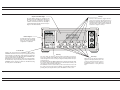
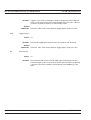
REAR PANEL
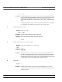
CONNECTORS
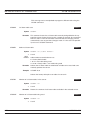
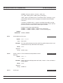
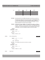
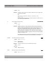
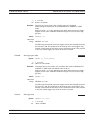
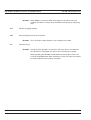
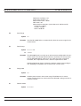
The Rear Panel connectors are illustrated and described in Figure 3-2.
.
3-2
ML2430A OM
OPERATION
REAR PANEL CONNECTORS
ID Number Label
Parallel Printer Port
GPIB/ IEEE488 Connector
Standard General Purpose Interface Bus connector used to connect through GPIB to other test
equipment and a host computer.
The ML2430A Series is compatible
with IEEE-488.1 requirements.
Refer to Chapter 6, GPIB Programming for information on using
GPIB.
Provides an interface to a standard parallel printer. Compatible
printers include the Canon BJC80,
HP 340 Deskjet, and most other
300 and 500 Series HP Deskjet
printers.
AC Main Power Input
The ML2430A Series ID
number is affixed to the rear
panel here. Please use the
complete ID number when
ordering parts or corresponding with the Anritsu
Customer Service department.
Chassis Ground
Used as a convenient earth ground
reference when DC line power is
applied and an optional safety
ground when operating from battery
power.
RS232 Serial Connector
Serial control and data output commands are
entered using the same format as the GPIB interface. Refer to Section 5-9 for more information on using Serial Remote Operation. Allows
communication with an Anritsu 68/69000-series
synthesizer in Source Sweep mode. Also allows
service access for software upgrades, etc. The
hardware handshake lines RTS and CTS are
used to control the flow of data.
DC Power Supply Input
Used for 12-24 VDC input in the absence of AC
line power. The optional battery can be fast
charged when the DC input voltage is greater
than or equal to 21V and all other functions are
off. Fast charge must be selected from the System menu. The external DC Power Supply input
line is protected by an internal fuse
Sensor Connectors
Alternate Sensor input connectors for Channels A and B. If the
rear panel optional connectors
are installed, the front panel
connectors are not installed.
Calibrator Connector
Alternate Calibrator output connector. If this rear panel connector
option is installed, the front panel
connector is not installed. Refer to
Chapter 5, Procedures, for information on using the Reference
Calibrator output.
85-264 VAC, 47-440 Hz, 40 VA maximum. The Power Meter automatically configures itself for the voltage applied. Connecting AC power here
will turn the instrument on. Subsequently, the instrument can be switched
between the ON state and the STANDBY state using the front panel
ON/OFF button. The optional battery can be fast charged when AC input
voltage is applied through this connector and all other Power Meter functions are off.
Output 2
Output 1
Multi-purpose BNC connector is user
configurable for Modulation Output
(TTL), Analog Output 1 (volts/units),
or Limits Pass/fail (TTL). Supports
pass/fail testing for channels 1 and 2.
Also configurable to output a
real-time measurement signal from
sensor input A, suitable for leveling
purposes.
Multi purpose BNC connector is user configurable for
Analog Output 2 (volts/units),
Blanking Zero (TTL), or Limits Pass/Fail (TTL). Supports
pass/fail testing for channels
1 and 2. Also configurable to
output a real-time measurement signal from sensor input B, suitable for leveling
purposes.
Input 2, Analog
Input 1, Digital
Multi purpose BNC connector is user configurable for Blanking Input
(used to ARM measurements in triggering
modes) or TTL Trigger
Input.
Multi-purpose BNC connector used for Volts per GHz connection. Supports 0 to
+20V nominal input voltage with software selectable scaling. V/GHz is used for
automatic CAL FACTOR correction by applying an external voltage, scaled to frequency. The correct calibration factor for this frequency is automatically interpolated and applied when in V/GHz calibration factor mode. Different scaling may be
applied to sensor A or B allowing for measurement of frequency translation devices. Available simultaneously with channel A and/or B data, the data rate is as set
on the channel. The default data rate is 20 ms in DEFAULT measurement mode
(with the default settling time of 0.1%), and programmable in PROFILE operation
mode and CUSTOM measurement mode.
Figure 3-2. ML2430A Series Rear Panel
ML2430A OM
3-3/3-4
Chapter 4
Front Panel Operation
4-1
4-2
INTRODUCTION
The ML2430A Series Power Meter is controlled from the front panel using the
five main menu keys; Sensor, Channel, Trigger, System, and Cal/Zero. This
chapter explains the power-on procedure and the features and functions of each
of the menus. Also refer to Appendix C for quick reference Menu Maps.
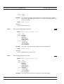
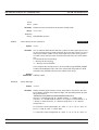
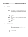
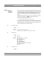
FRONT PANEL CONTROLS The front panel controls are shown and described in Figure 4-1. The following
sections provide more detailed explanations of the Menus and soft keys.
NOTE
Where appropriate, related GPIB commands are listed in brackets
under the menu selection. Refer to Chapter 6, GPIB Operation, for information on using GPIB commands.
NOTE
This manual is written for instruments fitted with software 3.00 or
above.
ML2430A OM
4-1
FRONT PANEL CONTROLS
OPERATION
Graphic LCD with Backlight
Soft Keys
The LCD display settings are configured in the
System menus. The backlight can be turned on or
off, or time delayed, as required to suit ambient
conditions and battery drain. The backlight is
controlled through the System menus when operating from the internal battery.
Soft keys select submenus, toggle selections,
control cursor position, and allow data entry. A
flashing cursor indicates when numbers can be
entered using the numeric keypad. Refer to the
following sections of this chapter for detailed information on using the soft keys.
Numeric Keypad
Provides the means for entering
numeric data in the appropriate
menus as required for system
configuration or calibration.
Power On /Off
Switches the power meter from STANDBY to ON, or ON to
STANDBY. Note that whenever AC power is applied, the power
meter defaults to the ON state. Subsequently, the instrument
can be switched between the ON state and the STANDBY state
using this front panel Power On /Off key.
When External or Internal (battery) DC power is first applied to
the instrument (no AC present) the power meter defaults to the
STANDBY state. It can then be switched to the ON state using
the front panel Power On /Off key.
Clear Key
The clear (CLR) key performs various functions depending on when it is
pressed. For example, when editing an entry in a menu, pressing the CLR key
clears the digits. If in a menu screen, pressing the CLR key returns to the previous menu level.
If the limits FAIL indicator HOLD audible alarm is sounding, pressing the CLR
key stops the alarm. The FAIL indication is not affected by the clear key, and
can only be cleared by turning fail hold off.
If the GPIB box is on the screen and the system is not in a menu screen, and
the system is in local mode (menus available), and no GPIB operations are
pending, then pressing the CLR key clears the GPIB box off the screen.
Menu Keys
When pressed, the first level submenus
appear on the display directly above the
soft key for that menu function. Refer to
the following sections of this chapter for
detailed information on using the menu
keys.
Figure 4-1. ML2430A Series Front Panel Controls
4-2
ML2430A OM
OPERATION
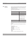
4-3
POWER-ON
PROCEDURE
POWER-ON PROCEDURE
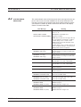
At power-on, the power meter performs a brief power-on self test (POST).
After the POST, the instrument loads the last used configuration and display settings. If a POST error occurs, information and available options
will be displayed on the screen.
The following tests are performed during the power-on self test, and also
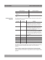
when the GPIB *TST? command is sent:
Table 4-1 Power-on Self Test
TEST SEQUENCE
POSSIBLE STATUS
Flash EPROM code checksum
Pass or Fail
Flash EPROM personality data checksum
Pass or Fail
Flash EPROM calibration data checksum
Pass or Fail
Volatile RAM tests
Pass or Fail
Non-volatile RAM checksums
Pass, Fail
WARNING - Software version
changed - all non-vol stores reset
Current store failed - current store
reset
Saved store(s) failed - failed store
status changed to not saved
WARNING - Secure mode clear
memory - all non-vol stores reset
Display
Pass or Fail
Keyboard
Pass or Fail
During the power-on self test, only failures and warnings will be displayed
on the front panel. If all tests pass successfully, no self test information is
displayed.
Failure and warning messages that can be displayed on the front panel
are:
Flash code csum
Personality csumVolatile RAM
Cal data csum
Non-Vol RAM
Software version - this is only a warning
Current Setup
Saved Setups
Secure - Mem clear - this is only a warning
Display
Keyboard
DSP error # - followed by a 4-digit hexadecimal error code
ML2430A OM
4-3
POWER-ON PROCEDURE
OPERATION
If any error, other than a DSP error, is encountered, the text:
“Press ANY key to continue”
will be displayed at the bottom of the screen. If only warnings are
encountered, nothing will be displayed at the bottom of the screen, and
the unit will continue to initialize.
If a DSP error occurs, the text:
"Restart unit. If error persists, con-tact Service Center."
is displayed and the unit will halt the self test. Make note of the hexadecimal error code displayed and contact your nearest Anritsu Service Center
(see Chapter 2, Table 2-1).
Self test error messages are also available over the GPIB, as a self test
status string (see STERR command, page 6-74).
4-4
ML2430A OM
OPERATION
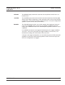
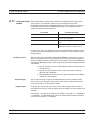
4-4
SENSOR MENU
SENSOR MENU
The Sensor menu has controls for sensor data processing.
NOTE
When editing an entry in a menu, pressing the CLR key
clears the digits. If in a menu screen, pressing the CLR key
returns to the previous menu level.
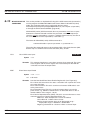
Setup
NOTE
The MODE selection is
not available in Profile
or Source Sweep
modes.
NOTE
When measuring modulated signals with a diode sensor, ensure
Modulated Average is
selected or measurement errors may result.
Selects the data acquisition controls for the sensor. The following submenus are
displayed.
SENSOR
Model ML2438A (dual channel) only. Select the sensor to be configured. Toggles between Channel A and Channel B for all submenu functions.
OPTION
Only displayed if a Universal Power Sensor with Option 01 is connected to selected input channel. This key selects between True
RMS sensor operation (for WCDMA measurements) and Fast CW
(for TDMA/Pulse measurements).
MODE
[SENMM]
Select either Default, Modulated Average, or Custom.
Default is the sensor mode setting following system preset. It is the
ML2430A Series simplest operating mode. Measurement speed is
automatically adjusted according to sensor response times and the
user-adjustable Settling %. Triggering controls, except for GPIB trigger, are disabled when the sensor mode is set to Default. This is intended to simplify basic power measurement by avoiding the
necessity of specific trigger settings.
Modulated Average mode is used to stabilize the front panel digital
readout. It is a specialized sensor mode for either MA2440A or
MA2470A Series power sensors. These sensors are fast enough to
demodulate the amplitude modulation of many RF test signals. The
Mod Average sensor mode is unnecessary for thermal power
sensors.
The Custom sensor mode permits the highest measurement rates.
Trigger controls are available with this sensor mode. Trigger Delay
(the time between the ML2430A Series receipt of a valid trigger
event and the start of sample integration) and Gate Width (the duration of sample integration) controls are located in the Trigger
menus.
When using universal power sensors only default mode is available unless OPTION is set to Fast CW. Fast CW can only be selected for sensors supplied with option 01.
ML2430A OM
4-5
SENSOR MENU
OPERATION
NOTE
The HOLD selection is
not available when
System/Setup/mode is
set to Source Sweep.
In this mode, AUTO
ranging is used.
NOTE
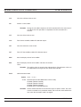
HOLD
[RGH]
Typical Range Hold values for diode sensors are:
SETTLE %
[SENSTL]
SETTLE% affects
GPIB speed. Consider
this when optimizing
GPIB performance.
Calfactor
Allows the operating range of the selected sensor to be set to the
desired range. Select a Range Hold value of 1 to 5, or Auto. When
in Auto, the range changes to take the best measurement automatically. Auto is the default setting following system preset.
Range 1
above approximately –12 dBm
Range 2
–10 to –27 dBm
Range 3
–25 to –42 dBm
Range 4
–40 to –57 dBm
Range 5
below –55 dBm
Settle % per reading is available when the sensor mode is set to
Default. The settling time allows some control over the tradeoff between speed and the extent to which a measurement has settled to
its final value. A 1% settling value relates to approximately 0.04 dB,
0.5% relates to 0.02 dB and 0.25% to 0.01 dB. The default value after a system preset is 0.1%, or about 0.004 dB. Increasing the Settle percent to 1% or more will substantially increase measurement
speed.
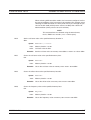
Allows entry of the calibration correction factor. The calibration factor compensates for mismatch losses and effective efficiency over the frequency range of the
power sensor.
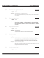
SENSOR
Model ML2438A (dual channel) only. Select the sensor to be configured. Toggles between Sensor A and Sensor B for all submenu
functions.
SOURCE
[CFSRC
CFVAL]
Three selections are available, Frequency, Manual, and V/GHz.
Frequency
NOTE
Frequency or V/GHz are preferred methods as the sensors have internal linearity
correction which varies with
frequency.
4-6
In this mode, correction data is read from the EEPROM in the sensor and applied automatically to the measurement based on the user’s input frequency. The EEPROM correction data value nearest to
the entered frequency is used to calculate the correction applied to
the signal.
ML2430A OM
OPERATION
SENSOR MENU
For greater accuracy, calibration factors are interpolated for settings
that are between the calibration factor data provided in the sensor
EEPROM. For example, if calibration factors exist for 1 and 2 GHz,
then the calibration factor applied for 1.5 GHz will be a value midway between the two.
NOTE
When the MA2499B Anritsu
Sensor Adapter or the
MA2497A HP Sensor Adapter
are used, the input frequency
should be set to 50 MHz irrespective of the measurement
frequency. Linearity correction factors are not applied
when the adapters are being
used.
Sensor linearity adjustments for temperature are also interpolated;
If the correction factor for 1.5 GHz at 25° C is 1 dB, and for 35° C is
1.1 dB, then at 30° C a value of 1.05 dB will be used.
Manual Set
Allows manual correction of sensor data either as a percentage or
a fixed dB value. An input frequency is also required to allow the
correct linearity correction factors to be applied.
V/GHz
Most modern synthesized sources have a rear panel BNC connector which outputs a voltage proportional to the synthesized frequency. The V/GHz is supplied to the rear panel input connector of
the ML2430A Series. The SETUP submenu has controls for customizing the voltage and frequency relationship.
NOTE
You will see a live update of the Current Cal
Factor only if that sensor is being used on a
channel. For example:
If you are editing the
Cal Factor Frequency
on Sensor B, but you
only have channel 1 set
to A and channel 2 off,
you will not see the
"Current Cal Factor"
being updated.
NOTE
User defined Cal Factor tables are available
for applications where
user-supplied calibration points are required. Additional cal
factor frequencies can
be entered in a user table and used in conjunction with the factory
table.
ML2430A OM
FREQ
[CFFRQ]
When the Cal Factor source is set to Frequency or manual, enter
the input signal frequency in GHz or MHz. The correct sensor calibration factor is automatically interpolated and applied to the displayed power reading.
USE TABLE
[CFUSEL
CFUTBL
CFUUSE
CFUVLD]
Defines which calibration factor table is to be used. Can be set to
Factory, table number 1-10, or Factory + table number. The maximum number of tables available is displayed on the screen, and is
never greater than 10. If a selected table has not been used before,
the user will be prompted to CLEAR or PRESET the table, or cancel the selection. If a table is CLEARED, all entries are cleared except for a single entry of 100% @ 50 MHz. If a table is PRESET the factory defined calibration factor table is copied into the specified user calibration factor table. The CLEARED or PRESET table
is saved directly to the sensor. PRESET clears the ID string, while
CLEAR leaves the ID string as currently set.
The number of tables available is defined by the frequency range of
the sensor and the amount of factory calibration data stored.
Delete
Deletes the currently displayed table number.
4-7
SENSOR MENU
OPERATION
Factory
Selects the Factory calibration factor table. Pressing Factory and
the +/- key on the numeric keypad allows selection of a userdefined table in addition to the factory table. This allows full factory
calibration to be active, and allows adjustments or corrections to be
entered in the user-defined table. If user table 1 was selected, the
menu would show ‘Factory+1’ and the Status box on the readout
display would show a warning ‘*’ sign on the Cal Factor line (bottom
text line in the box) to show that non-standard calibration is being
applied (CAL *F or CAL *V).
NOTE
Whichever set, or sets,
of cal factors are used,
the linearity and temperature correction remains active at all
times. Ensure the
power meter is programmed with the frequency of the signal
being measured.
Enter
Confirms the selection.
%/dB
[CFUNITS]
Toggles the Current Cal factor display format from percentage to
dB, and back.
EDIT
[CFUADD
CFUSAV
CFUCT
CFUPT
CFULD
CFURD
CFUID]
Edit any of the available user calibration factor tables in the sensor.
Options available are CLEAR or PRESET the table, enter a new table identity string, change or delete existing frequency/cal factor
data pairs, or enter new frequency/cal factor data pairs. All frequency/cal factor data pairs can have both frequency and calibration factor value modified, except for the data pair at 50 MHz, which
can only have its cal factor value changed. All frequency/cal factor
data pairs can be deleted, but there must always be one data pair
remaining. If there is a data pair at 50 MHz, this will be the data pair
that will remain.
The user must ensure that the maximum number of cal factor data
pairs entered into a table is not exceeded. Sensors with a maximum frequency of up to 40 GHz will hold 90 pairs, while sensors
with a maximum frequency of 50 GHz will hold 110 pairs.
Once all changes have been made, the SAVE soft key saves the
changed data to the sensor. If any user cal factor data is changed
and not saved, any attempt to exit the cal factor menu or select a
new table will result in a prompt to discard or save the changes.
NOTE
Manual Cal Factor
method only.
4-8
FACTOR
[CFCAL]
When the Cal Factor Source is set to Manual, the operator is expected to enter the calibration factor value in dB or % terms.
CAL
ADJUST
[CFADJ]
Sets a calibration factor to be used when performing a 0 dBm calibration and the calibration factor source is set to 'Manual.' This
value is the only factor applied when performing a 0 dBm reference
calibration. If the sensor calibration factor source is set to V/GHz or
Frequency, the sensor internal EEPROM correction value at 50
MHz is used.
ML2430A OM
OPERATION
SENSOR MENU
SETUP
[CVSTF
CVSPF
CVSTV
CVSPV]
Averaging
Sets up the Start and Stop frequencies and voltages when Source
is set to V/GHz. This tells the ML2430A how to determine the frequency of the swept signal based on the applied rear panel voltage.
Sensor data averaging. The available soft keys depend upon the operating mode
selected.
In Readout and Power vs. Time modes, the following soft keys appear:
SENSOR
Model ML2438A (dual channel) only. Select sensor A or B, in Power
vs. Time or Readout modes.
MODE
[AVG
AVGM]
Select OFF, AUTO, MOVING or REPEAT, in Power vs. Time or
Readout modes.
AUTOMATIC averaging uses a MOVING type of average and increases the amount of averaging as the noise level increases. The
display updates at approximately 100 ms intervals, however the
data is available at the full rate. The display is slowed down to prevent jitter and allow the user to follow the update.
NOTE
Automatic averaging
also applies an algorithm to enhance settling at low power levels
(e.g.,signal sources).
MOVING average allows the user to manually select the amount of
averaging regardless of the signal level. The display is continually
updated while averaging.
When selected, the following soft key becomes available:
NUMBER
[AVG
AVGM]
ML2430A OM
Sweep averaging number (1 to 512).
4-9
SENSOR MENU
OPERATION
REPEAT averaging also allows the user to manually select the
amount of averaging regardless of the signal level, however the display is updated only when the NUMBER of readings specified have
been taken (1-512).
NOTE
GPIB trigger commands automatically
apply REPEAT averaging after TR2 commands to ensure ‘old’
samples are excluded
from the measurement.
However, the user
should be aware that
due to the high speed
of the meter, other instruments in the ATE
system may not be settled.
NOTE
Due to the nature of this method of operation, if the power
level changes between updates, the display update will not
reflect the true input power for one measurement only.
When a channel is set to a ratio, e.g., A–B or A/B etc., the
repeat method described above only operates if all sensors
are set to the REPEAT mode.
LOW
LEVEL
[AVGLL]
Select OFF, LOW, MEDIUM, or HIGH, Low Level Averaging, in
Power vs. Time or Readout modes. Sets the low level averaging
window for the sensor. At resolution settings of 0.01 and 0.001 dB,
digital readouts may flicker due to the high reading rate of the
power meter. Low level averaging applies a low pass filter to postaverage data readings to achieve a more stable front panel display
without slowing down the response of the meter to larger changes
in level. The three windows for LOW, MEDIUM and HIGH low level
averaging are ± 0.01, 0.02, and 0.05 dB.
For example: When a LOW setting of low level averaging is applied
while stepping from 0 dBm to –1 dBm, the meter displays the final
reading within 0.01 dB with no delay. The final settling of 0.01 dB
will settle over a short subsequent period of time, leading to a stable high resolution readout.
With a HIGH setting of low level averaging, the settling window is
increased (up to approximately 0.05 dB) and the settling time is
longer.
With low level averaging OFF, the meter displays the final reading
instantly with no further settling observed. Any jitter due to noise is
reflected in the displayed reading, which may be inconvenient for
high resolution readings.
In Profile and Source sweep modes, the following soft keys appear:
STATE
[GRSWS]
Graph averaging state, ON or OFF. When set to ON, the following
additional soft keys appear:
A NUMBER [GRSWP]
B NUMBER (ML2438A only) [GRSWP]
Sweep averaging number (1 to 512).
4-10
ML2430A OM
OPERATION
SENSOR MENU
RESET
Sweep average reset. If the graph sweep averaging state is ON,
this key resets the data points and restarts the sweep to sweep
mode.
CURSOR
[GRSWR]
Offset
Between cursor averaging ON or OFF. When ON, a digital readout
of the average power between the two cursors is displayed in the
readout area of the PROFILE display.
Allows an offset, in dB, to be applied to sensor data for the selected sensor.
SENSOR
Model ML2438A (dual channel) only. Used to select the sensor to
be configured. Toggles between Channel A and Channel B for all
submenu functions.
TYPE
[OFFTYP]
Selects the type of offset to be applied:
Off
No offset applied.
Fixed
A fixed dB offset VALUE is applied to the sensor data.
NOTE
Table
Use Fixed or Table to
compensate for a fixed
attenuator on a sensor
for measuring higher
power levels. A better
method is to apply a
Fixed cal factor in the
User tables as this is
then taken into account
in the Zero/Cal process.
The tables are a set of frequency-against-dB offsets. The offset
value used from the table depends on the setting of the frequency
correction source. If the source is FREQUENCY, the entered frequency is used to calculate the offset from the table. If the frequency correction source is V/GHz, the frequency value calculated
from the supplied ramp input is used to calculate the offset from the
table.
If the frequency does not match any frequency in the table, interpolation is used to calculate the correct offset.
NOTE
If the frequency is greater than the maximum frequency in
the table, the offset value from the maximum table frequency is used. If the frequency is less than the minimum
frequency in the table, the offset from the minimum table
frequency is used.
VALUE
[OFFFIX
OFFVAL]
ML2430A OM
Enter the offset value (dB) when Offset TYPE is set to Fixed. Valid
range is –99.99 to +99.99.
4-11
SENSOR MENU
OPERATION
TABLE
[OFFTBL
OFFTBR
OFFTBU
OFFVAL]
Select the offset table number (1-5) when Offset TYPE is set to Table. When a table is selected, additional soft keys become
available:
EDIT
This will bring up all of the selected offset table’s entries, with their
associated frequencies and offsets. Select an entry and enter the
frequency and offset using the keypad.
CLEAR [OFFCLR]
When an offset table is selected, CLEAR will set all of the table’s
elements to zero.
Duty cycle
Rng Hold
[RGH]
NOTE
Rng Hold is not available
when System|Setup|mode
is set to Source Sweep. In
this mode, AUTO ranging is
4-12
Applies a duty cycle to the selected sensor. An offset will be applied based on the
entered value.
SENSOR
Model ML2438A (dual channel) only. Used to select the sensor to
be configured. Toggles between sensor A and sensor B for all submenu functions.
STATE
[DUTYS]
ON or OFF
DUTY
[DUTYS]
Delete, Enter, or Cancel. An offset will be applied based on the entered value. For example, specifying a duty cycle of 50% will alter
the displayed readings by approximately +3.01 dB.
This function will toggle the sensor between holding the present operating range
and Auto Ranging. Auto Ranging automatically selects the best range to take the
measurement.
If either sensor is auto ranging, this key will force both sensors to hold their present operating ranges. If either sensor is held within an operation range, this key
will force both sensors to Auto Range.
ML2430A OM
OPERATION
4-5
CHANNEL MENU
CHANNEL MENU
The Channel menu controls the operation of a display channel. There are two
display channels, Channel 1 and Channel 2. Channel 1 appears at the top of the
readout display and channel 2 at the bottom. If a channel input configuration is
turned off, the remaining channel appears in the center of the screen.
NOTE
When editing an entry in a menu, pressing the CLR key
clears the digits. If in a menu screen, pressing the CLR key
returns to the previous menu level.
The Channel submenus are as follows:
Setup
NOTE
Use MIN/MAX to track
variations in a measurement over time, or
while adjusting external devices or tuning
over frequency.
ML2430A OM
The setup menu allows the user to set up the configuration of the display channels. The setup parameters are:
CHANNEL
Selects the channel to be configured. Toggles between Channel 1
and Channel 2.
INPUT
[CHCFG]
This is the sensor, combination of sensors, or rear panel BNC input
that is used to calculate the measured and processed value for this
channel. For the Model ML2437A (single input) power meter, the
available options are A, External Volts, or OFF. For the ML2438A
(dual input) power meter, the options are A, B,
A – B, B – A, A/B, B/A, External Volts, or OFF.
UNITS
[CHUNIT]
The units can be dB(m), Watts, dBµV, or dBmV. If the External Volts
input is selected, the units are fixed to Volts.
RESOLUTION
[CHRES]
The number of decimal places in which the results are displayed in
Readout mode, with certain limitations. If the units selected are in
Watts or Volts, and the value goes down to pW or µV, the number
of decimal places is forced to zero. If the number to be displayed is
too large for the number of decimal places selected, the decimal
places displayed will be reduced.
MIN/MAX
[MNMXS
GMNMX]
This selection turns on the Min/Max Tracking for the display channel selected. On the top line of the data display, when not in menu
mode, the min and max of the channel data (after combination and
unit conversion calculations) is displayed. The left hand set of data
is for display channel 1 and the right hand set for display channel 2.
In Profile mode, the Min/Max is between cursors only, as controlled
by selecting SINGLE or INFINITE through the
System|Graphics|TRACKING menu. SINGLE (default) is the most
useful as it provides a continuously updated readout of the Min/
Max points within the cursor window. The INFINITE setting is used
when the results needs to be collated over a large number of
samples.
4-13
CHANNEL MENU
OPERATION
RESET
[MMRST]
Rel 1
[REL]
This function resets the Min/Max (when ON) for the channel
selected.
After the relative power level is set by the operator, the Relative mode subtracts
that value from the current measured power. If selected when in Relative mode,
the relative operation for channel one is turned off.
Pressing the Rel 1 soft key when in Readout mode will subtract the last used
relative value. Hold down the key to retake this value. The readout will display
0.00 dBr. This relative value will be used thereafter until it is replaced by another
one in the same manner. This allows the user to refer to a previously referenced
value, without the meter resetting itself back to a 0.00 display.
Rel 2
[REL]
Limits
Relative mode control for Channel 2 is labeled Rel 2.
Pressing the Limits menu soft key displays the test limits for the selected channel.
This menu sets individual high and low pass/fail limits for the two display channels. These limits drive the PASS/FAIL display flags and the PASS/FAIL TTL output if selected.
In Power vs. Time graphic mode and Readout digital mode, each fail of the limits
produce a separate fail flag and fail beep (if ON) and also drive the rear panel
BNC (if enabled) for each pass or fail reading. In PROFILE mode, each fail of the
limits produce a fail beep (if ON) and hold the fail output if any point in a sweep
fails. If FAIL indicator HOLD is ON, both the screen FAIL indicator and the BNC
output are held in the fail state whenever the limits specified for the channel have
been exceeded, regardless of whether the reading subsequently goes into pass
or not. This state remains until FAIL indicator HOLD is turned OFF.
CHANNEL
The limits are set for the selected display channel unit type. The
display channel units selected when the limit was originally set or
turned on become the limit units. If the display channel units are
changed, and the limits not altered, limit checking is turned off for
that channel. If the display channel units are subsequently returned
to the same units selected when the limit was entered or turned on,
limit checking is turned on again.
Whenever the limit units are active, limit checking is applied as follows: If the channel value is greater than the high limit, and the high
limit is turned ON, a FAIL is indicated. If the channel value is below
the low limit, and the low limit is ON, a FAIL is indicated. Otherwise,
if any limit is ON and a FAIL is not detected, PASS is indicated.
HIGH Limit
[HLIM]
4-14
Sets the high limit. It is not necessary to enter the units as the limit
value is checked against the displayed value. Therefore, if the limits
ML2430A OM
OPERATION
CHANNEL MENU
have been set for –10 dBm and the display units are subsequently
changed from dBm to Watts, the system still checks for the reading
to rise above –10, even though the display units type has been
changed. Enter a value from:
NOTE
In Profile mode, the
limit value is only
checked against dB
values as Profile mode
only works in dB.
Units
Min
Max
dBm
–99.99
+99.99
dBmV
–53.00
147.00
dBµV
7.00
207.00
Watts
0.0
50.0
Setting a limit value automatically turns on the limit state, except
when done via GPIB.
LOW Limit
[LLIM]
Sets the low limit. It is not necessary to enter the units as the limit
value is checked against the displayed value.
HIGH State
[HLIMS]
Select ON or OFF to enable or disable high limit checking.
LOW State
[LLIMS]
Select ON or OFF to enable or disable low limit checking.
FAIL HOLD
[FHOLD]
If FAIL HOLD is ON, both the screen FAIL indicator and the BNC
output are held in the fail state whenever the limits specified for the
channel have been exceeded, regardless of whether the reading
subsequently goes into pass or not. This state remains until FAIL
HOLD is turned OFF.
BEEP
[FBEEP]
If BEEP is ON, and FAIL HOLD is OFF, whenever the limits specified for the channel have been exceeded, a single beep sounds.
If fail BEEP is ON and FAIL HOLD is ON, whenever the limits
specified for the channel have been exceeded, a beep will sound
once every second until FAIL HOLD is turned OFF, or the CLEAR
key (CLR) is pressed.
The FAIL indication is not affected by the CLEAR key, and can only
be cleared by turning FAIL HOLD off. If a limit fail happens again,
the alarm will sound again.
ML2430A OM
4-15
TRIGGER MENU
4-6
TRIGGER MENU
OPERATION
The Trigger function in the ML2430A allows the user to define under what conditions measurements are taken, and the time period they are taken over. For instance, the READOUT mode can be configured to display the average power of
the ON period of a square wave, or an individual slot in a GSM burst.
The Trigger menus are always available in PROFILE operation mode, as selected
from the System menu. If PROFILE cannot be selected within the System|Setup
submenu, change the GPIB mode to ML24XX in the System|Rear Panel
submenu.
In READOUT or POWER vs. TIME modes, the trigger setup menus are available
if the channel input configuration SENSOR|Setup|MODE is set to CUSTOM. A
display channel using more than one sensor (A–B for example) where either sensor is in CUSTOM mode, is assumed to be in custom mode and can use triggering. Trigger setup is available only for the display channels that meet the above
criteria.
In PROFILE mode, the display shows an ‘x’ marking the trigger point plus the display trigger delay time, updated for each new set of data. This trigger point mark
rotates as the profile data is updated, changing between '´' and '+' on each data
update. On rapid updates, the trigger point mark may appear like a star (S), as it
is rotating so quickly. In manual, external or GPIB triggered displays, the mark rotates at a slower rate and each true data update can be seen.
This point can be moved across the x axis by the pre trigger percentage. If the
trigger source is either default, mod average or custom continuous, the trigger
point has no meaning since the system is continuously triggering. The mark does
not appear in the Power vs. Time or Source Sweep modes, as it is not applicable.
Trigger icons indicate the type of triggering selected and appear level with the related channel on the far left of the screen. Trigger icons are not displayed if the
system is in Profile, Power vs. Time, or Source Sweep operation modes, if all
sensors used in a channel input configuration are in the DEFAULT measurement
mode, or if the peakmeter is displayed.
NOTE
When editing an entry in a menu, pressing the CLR key
clears the digits. If in a menu screen, pressing the CLR key
returns to the previous menu level.
4-16
ML2430A OM
OPERATION
TRIGGER MENU
The trigger icons appear as shown in Figure 4-2.
Modulated Average
MOD
Continuous
Manual
Rising Edge
Falling Edge
Internal A
INT
A
INT
A
Internal B
INT
B
INT
B
TTL
TTL
NOTE
External trigger is only
effective at 800 KHz or
lower.
MAN
External
Figure 4-2. Trigger Icons
Only when a channel input configuration includes a sensor with a measurement
mode that requires an icon, will an icon be displayed.
Setup
NOTE
Simultaneous trigger
channels guarantee
identical sampling for
both channels, essential for accurate ratio
(A/B) measurements.
ML2430A OM
This menu is used to set up the trigger conditions for the display channels. In
readout display mode with sensor mode set to custom, the trigger can be set to
display channel 1 and 2 separately, or together as channel 1 & 2.
The channels are triggered simultaneously if the trigger conditions are set to 1 &
2. This guarantees the trigger conditions are the same, and therefore the readings are taken at the same time. In Readout and Power vs. Time modes, if the
menu is exited with the trigger selection at channel 1 & 2, this setup is used for
trigger control. Otherwise, if the trigger setup display is left with channel 1 or
channel 2 displayed, the individual trigger settings are used for trigger control.
CHANNEL
[TRGMODE]
Select display channel 1 or 2 (or 1&2 when setting trigger conditions in Readout or Power vs. Time modes).
SOURCE
[TRGSRC
GTSRC]
The trigger sources are CONTINUOUS, Internal A, Internal B
(ML2438A only), EXTTTL, or MANUAL . When the trigger source is
set to INT A or INT B (Internal A or B) the power meter triggers on
a rising or falling power level on the associated sensor. See LEVEL
for the setting of the trigger power level.
4-17
TRIGGER MENU
OPERATION
DELAY
[TRGDLY
GTDLY]
In Profile mode, DELAY sets the time delay (after the display trigger
delay) to when the system starts to take and display readings, represented by the left most cursor. Enter 0.0 to 1.0 seconds, in ms or
ms.
NOTE
Changing the left most cursor, or the trigger delay time, updates the cursor or the delay time value accordingly. In Profile mode, moving the cursor only allows updates to the
pixel resolution of the display. In Power vs. Time mode, the
delay and width can be used to alter the update rate.
In Readout mode (CUSTOM sensor mode), the value entered for
DELAY is applied after a trigger event, and before samples are
taken. Enter 0.0 to 1.0 seconds, in ms or ms.
NOTE
WIDTH
[TRGGW
GTGW]
The averaging function
averages a number of
gate WIDTHS, so for a
given averaging number, larger WIDTHS will
take longer to AVERAGE. Narrower widths
will average faster (but
may yield a less-settled
measurement).
NOTE
Use Arming to synchronize to other equipment
or modulation/burst
synchronization. This
is a simple way to
inhibit measurements
during user-defined periods without entering
actual time periods.
4-18
Enter 100 ns to 7.0 seconds (the default is 20 ms). In Profile mode,
WIDTH is the gate time the system uses to perform a cursor average measurement. The time interval is represented by the space
between the left most cursor and the right most cursor. Changing
either cursor, or the gate width value, updates both the cursors and
the gate width value.
In Readout mode, this value defines the measurement gate width.
A measurement is presented as the average of all data taken in this
gate width.
In Power vs. Time mode, the delay and width can be used to alter
the update rate or sample rate.
EDGE
[TRGXTTL
GTXTTL]
When set to External TTL, the power meter triggers on a TTL level
rising or falling. This selection sets the trigger for either a rising or
falling edge.
ARMING
[TRGARM
GTARM]
Sets the trigger arming, unless the trigger source is set to EXTTTL.
When ARMING is set to Blanking ON, only samples taken when
the rear panel Digital Input BNC is active will be averaged in the
measurement. The polarity of the rear panel Digital Input BNC signal can be set (high or low) using the System|Rear Panel|BNC|TTL
LEVEL menu setting.
When ARMING is set to Blanking OFF, all samples are read irrespective of the level on this BNC.
Figure 4-3 shows a typical arming diagram.
ML2430A OM
OPERATION
TRIGGER MENU
-9
GSM BURST
FROM GENERATOR
dBm
-50
BURST TRIGGER SYNC
FROM GENERATOR
TTL
Figure 4-3. Typical Arming Diagram
1. Connect to the rear panel digital input.
2. Select Trigger|Setup|ARMING|Blanking ON.
3. Set the polarity of the blanking (System menu)
Example power meter reading: –9.16 dBm.
NOTE
Effective range is to approximately –30 dBm
and is only active in DC
ranges 1 and 2.
ML2430A OM
TYPE
[TRGTYP
GTTYP]
The Type selection (RISE or FALL) sets the trigger for a rising or
falling edge. When the trigger source is set to INTA or INTB (Internal A or B) the power meter triggers on a power level which is rising
or falling.
LEVEL
[TRGLVL
GTLVL]
The Level selection sets the internal trigger level. When the trigger
source is set to either INTA or INTB (internal sensor A or B) the
channel triggers on a power level (in dBm) given by the sensor.
This value must not take any cal factors or offsets that the meter
applies into account.
Trig 1
If Trigger Channel 1 SOURCE is set to Manual, this softkey initiates
a measurement for channel 1.
Trig 2
If Trigger Channel 2 SOURCE is set to Manual, this softkey initiates
a measurement for channel 2.
Trig 1&2
If Trigger Channels 1 and 2 SOURCE are set to Manual, this
softkey triggers both channels simultaneously.
4-19
TRIGGER MENU
OPERATION
Figure 4-4 shows a typical trigger timing diagram. Note that the display
trigger delay is only present when in Profile operation mode, and helps in
setting the ‘window’ position along the signal.
PRETRIGGER %
CURSOR
1
CURSOR
2
GATE
WIDTH
DELAY
INCOMING SIGNAL
FROM SENSOR
DISPLAY TRIGGER DELAY
(PROFILE MODE)
DATA COLLECTION TIME
(PROFILE MODE)
TRIGGER POINT
Figure 4-4. Sample Trigger in Graphic Mode
The Data Collection Time (collection period) is only present when in Profile operation mode (System|Profile|PERIOD), and is the period of time
displayed on the profile graph.
The Gate Width is the section of the signal in which the measurements
are performed. In Profile mode, this is the time between Cursor 1 and Cursor 2 and is used to provide the Between Cursor Average measurement.
Display Trigger Delay (System|Profile|DELAY) is the delay after the trigger
point.
NOTE
External trigger is only
effective at 800 KHz or
lower.
4-20
The Pretrigger % (System|Graphics|PRE TRG%) is only used in the Profile mode, and shows a percentage of the data collection time as Pretrigger information. If the display trigger delay is less than the pretrigger delay
period, there will be no Pretrigger information as it will be before the trigger point itself.
Setting the display trigger delay to the length of the data pulse causes a
trigger on the first pulse, but displays the second pulse with valid “pretrigger information.” This is the best method for repetitive signals and can be
used to verify signal repetition intervals.
ML2430A OM
OPERATION
4-7
SYSTEM MENU
SYSTEM MENU
The System menus control the operating modes, display visibility, sound, rear
panel functions, and battery state of the ML2430A Series Power Meter. Note that
the soft keys will appear differently depending upon the operation mode selected
with the Setup soft key below.
NOTE
When editing an entry in a menu, pressing the CLR key
clears the digits. If in a menu screen, pressing the CLR key
returns to the previous menu level.
Setup
NOTE
When using the
ML2430A
Series
Power Meter with an
MA2499A or MA2499B
Sensor Adapter, only
Readout and Power vs.
Time modes are allowed.
This menu selects the operation mode, allows system setups to be saved or recalled, and provides two options to reset the system parameters to the default
setup.
MODE
[OPMD]
Select between Readout, Power vs. Time, Source Sweep and Profile operation modes. If only Readout is available, check the System|Rear Panel|GPIB|Mode setting. This setting must be ML24XX
for Profile, Power vs. Time and Source Sweep modes to be
available.
SAVE
[*SAV
SYSLD
SYSRD
SYSLNM]
Save the current instrument setup in one of 10 memory locations.
RECALL
[*RCL
SYSLD
SYSRD
SYSLNM]
Recall a saved instrument setup from one of 10 memory locations.
LINK
[LINK]
There are two trigger conditions saved; one for Profile mode and
one for Readout mode. Normally, Profile mode trigger conditions
can be changed without affecting the trigger conditions used in
Readout mode. With LINK set to ON, the Profile mode trigger conditions are used for both Profile and Readout modes.
In Profile mode, the user can view what is being measured with the
selected trigger conditions, but only over a limited dynamic range,
as it only uses the two DC ranges of the signal channel. Profile
mode measurement rate is also limited by sweep speed.
ML2430A OM
4-21
SYSTEM MENU
OPERATION
With LINK readout/profile trigger set to ON, switching to Readout
mode uses the same trigger conditions, but allows the full dynamic
range of the meter to be used, as well as providing full GPIB speed
on data acquisition.
NOTE
With LINK set to ON,
Readout mode is temporarily forced to Custom mode, and the default and Mod Average
modes are inhibited. To
use these modes, deselect LINK.
When moving between Readout and Profile modes, with LINK enabled, the value used for “sample delay” is modified using the
“display trigger delay.” In Readout mode, the “sample delay” and
“display trigger delay” values are combined as “sample delay,”
whereas in Profile mode they are both available separately.
FAST
Fast recall of a saved instrument setup from one of the 10 memory
locations. In FAST system recall mode, a single key press recalls a
saved setup. A message across the lower area of the screen will
prompt for keypad keys 1-9, or 0, to be pressed to recall setups
1-10 (if saved setup data is available in the selected location). The
-exit- softkey or any other menu key will exit fast recall mode.
PRESET
Resets the system parameters to the default setup (see Appendix
A, Section A-3).
RESET [*RST]
This selection will reset the system setup. The offset tables and the
GPIB interface will not be affected.
FACTORY [FRST]
This selection will reset the system setup, including the offset tables and GPIB interface.
Profile
NOTE
PERIOD sets
x-axis time.
CHANNEL
[GRMD]
Select Channel 1 or Channel 2. The channel selected will be displayed on the left of the screen, above the middle value of the y
axis and is used for all Profile data displays.
PERIOD
[GRPRD]
Sets the time period over which the system collects data and
scales the data into the profile graph after a trigger event. Enter the
data collection period in ms or µs. See System|Graphics|Pretrig %
to move the t=0 (trigger event position) of the displayed waveform.
DELAY
[DTRGD]
Specifies the period of time after a trigger event to delay the start of
the display window. For the trigger to line up with the marked trigger
point on repetitive waveforms, the delay period should be either
zero, or set to integer multiples of 1/PRF (Pulse Repetition Frequency). Enter the delay period in ms or µs.
the
NOTE
This is Display Trigger
Delay in Figure 4-4.
4-22
This soft key becomes available when the System|Setup|MODE is set to Profile.
Profile operation mode includes the following display controls:
ML2430A OM
OPERATION
NOTE
SYSTEM MENU
DATA HOLD
[GRPIX]
This selects how the graph is displayed on the screen. Select from
NORMAL, Min&Max, Min, or Max.
NOTE
If either Min&Max, Min, or Max is selected, the display will
keep the “old” data and may appear stationary. The DATA
HOLD mode in use is displayed on the left of the screen,
below the middle value of the y axis.
Useful for tracking
peak levels over a period of time, or detecting glitches.
With Min & Max selected, the minimum and maximum points for
each sample are shown. If Connect Points is ON (default)
(SYSTEM|Graphics|CONNECT), a vertical bar is drawn between
these points. See CLEAR, under CONTROL to restart the process.
Min displays only the minimum for this sample position until reset
by returning to NORMAL.
Max displays only the maximum for this sample position until reset
by returning to NORMAL.
Power vs. Time
This soft key becomes available when the System|Setup|MODE is set to Power
vs. Time mode. Power vs. Time mode displays measurements in a chart-like format showing history over a period of time. The measurements displayed are
taken under the conditions of the Readout mode, and can therefore include all
triggering and correction settings set up in that mode.
Power vs. Time operation mode includes the following display control:
Source sweep
ML2430A OM
CHANNEL
[GRMD]
Select Channel 1 or Channel 2. The channel selected will be displayed on the left of the screen, above the middle value of the y
axis.
DATA HOLD
[GRPIX]
Selects how the graph is displayed on the screen. Select from
NORMAL, AVG, Min&Max, Min, or Max.
TIME
[GRDDT]
Sets the data hold time, from 1 minute to 24 hours.
This soft key becomes available when the System|Setup|MODE is set to Source
Sweep. The Source Sweep mode provides interconnection between a signal
source/generator and the power meter. Using simple techniques, this can provide
swept power-accurate measurements over any frequency range at very high
speed. The sweep data is available over GPIB and can provide a simple low cost
scalar analyzer function.
4-23
SYSTEM MENU
OPERATION
Anritsu 68/69000 Synthesized Sweep Generator
HORIZ OUT
10 MHz
REF IN
NOTE: USE SLOW BLO FUSES ONLY
10 MHz
REF OUT
!
HORIZ
OUT
HEAVY WEIGHT
SEQ
SYNC
OUT
LINE
SELECT
!
ML2430A Series Power Meter
CAUTION
DIGITAL INPUT 1
DO NOT OPERATE
WITH POWER CORD
UNGROUNDED
EXT
ALC
IN
INPUT
90 - 132VAC
180 - 264VAC
48 - 440Hz
DWELL
IN
V/GHz
OUT
110
220V
2.5A
110V
5A
220
AUX I/O
CAUTION
> 18 kg
ANALOG INPUT 2
IEEE-488 GPIB
SERIAL
I/O
SEQ SYNC OUT
BNC Cables
Figure 4-5. Source Sweep Mode Interconnection Example
If the source used does not provide a blanking output, the blanking signal may be
disabled as follows: select System|Rear Panel|BNC. Select PORT until INPUT 1
(digital) is selected, then select TTL Level to alter the active state of the blanking
signal expected. Setting the TTL Level to LOW will allow the Source sweep to
progress without a Blanking signal. This is useful for third party sources or simple
VTO systems. If a Source Sweep is later selected which does provide a blanking
signal, remember to restore the polarity of this signal to HIGH or an incorrect display will result. Operating a source sweep which has BANDSWITCH blanking delays in it without an appropriate blanking signal may lead to glitches in the
resulting measurement at the bandswitch points (simple VTO systems do not
usually have bandswitch points).
Source sweep operation mode includes the following display controls:
NOTE
If either Min&Max, Min,
or Max is selected, the
display will keep the
“old” data and may appear stationary. The
DATA HOLD mode in
use is displayed on the
left of the screen, below
the middle value of the
y axis.
4-24
CHANNEL
[GRMD]
Select Channel 1 or Channel 2. The channel selected will be displayed on the left of the screen, above the middle value of the y
axis.
DATA HOLD
[GRPIX]
This selects how the graph is displayed on the screen. Select from
NORMAL, Min&Max, Min, or Max.
With Min & Max selected, the minimum and maximum points for
each sample are shown. If Connect Points is ON (SYSTEM|Graphics|CONNECT), a vertical bar is drawn between these points. Min
displays only the minimum for this sample. Max displays only the
maximum for this sample.
MODE
[SRCMOD]
Source sweep mode: FREQUENCY or POWER.
START
Sweep start frequency (MHz or GHz) or power (dBm)
[SRCSTFRQ
SRCSTPWR]
ML2430A OM
OPERATION
SYSTEM MENU
STOP
Sweep stop frequency (MHz or GHz) or power (dBm)
[SRCSPFRQ
SRCSPPWR]
NOTE
When the power meter is communicating with a signal
source/generator over the serial interface, if the source frequency power level or the frequency itself is changed, the
source sweep display will be updated where appropriate.
Control
The Control menu adjusts cursor position and toggles the readout display in Profile, Power vs. Time and Source Sweep modes, and provides control over display
scaling.
SWAP
<<
>>
[CUR]
SWAP selects which cursor to move. The presently selected cursor
is defined by a triangular marker at the top of the cursor line. Press
the << soft key to move the selected cursor left, and the >> soft key
to move the selected cursor right. Trigger delay and Gate Width are
related to the cursor positions. This feature aids in measurement of
pulsed signals. Changing either cursor, or adjusting the Gate width
value, updates both the cursors and the gate width value.
When enabled through the System|Sound|CURSOR menu selection, if a cursor is moved into an illegal space such as the edge of
the screen or the end of valid data (trigger point on the left of the
screen) a warning beep will sound.
SCALE
[GRYT
GRYB]
Adjust the Y-axis of the graph using TOP dB Value and BOTTOM
dB Value parameters in the SCALE submenu. AUTO scale is based
on the min and max of the previous sweep.
READOUT
[GRDATA
GRDRQ]
The supplemental data readout is displayed or removed with the
READOUT soft key. The readout provides display data depending
on the graph mode and the data hold type selected, as shown
below.
ACTIVE CURSOR
AVERAGE READING
BETWEEN CURSORS
1 -10.61 dB
2 -12.63 dB
P -0.00 dB
t 8.85 mS
AV -17.41 dB
Figure 4-6. Sample Readout Display, Profile Mode, Data Hold = NORMAL
Profile Mode
Data hold = NORMAL:
ML2430A OM
4-25
SYSTEM MENU
OPERATION
1
cursor 1 reading
2
cursor 2 reading
DP
Power difference between cursor 1 and cursor 2
Dt
Time difference between cursor 1 and cursor 2
AV
Between cursor average if ON
Data hold = MIN (or MAX) :
1
cursor 1 minimum reading, or maximum if MAX mode
2
cursor 2 minimum reading, or maximum if MAX mode
DP
Power diff between cursor 1 and cursor 2 minimums
(or maximums if MAX mode)
Dt
Time difference between cursor 1 and cursor 2 minimums
(or maximums if MAX mode)
Data hold = MIN&MAX:
1
cursor 1 MIN reading
cursor 1 MAX reading
2
cursor 2 MIN reading
cursor 2 MAX reading
Dt
Time difference between cursor 1 and cursor 2
Power vs. Time Mode
Data hold = NORMAL or AVERAGE:
1
cursor 1 reading
2
cursor 2 reading
DP
Power difference between cursor 1 and cursor 2
T1
Time at cursor 1
T2
Time at cursor 2
Data hold = MIN (or MAX) :
1
cursor 1 minimum reading, or maximum if MAX mode
2
cursor 2 minimum reading, or maximum if MAX mode
DP
Power diff between cursor 1 and cursor 2 minimums
(or maximums if MAX mode)
T1
Time at cursor 1
T2
Time at cursor 2
Data hold = MIN&MAX:
1
cursor 1 MIN reading
cursor 1 MAX reading
2
cursor 2 MIN reading
cursor 2 MAX reading
Dt
Time difference between cursor 1 and cursor 2
Source Sweep mode
Data hold = NORMAL or AVERAGE:
1
4-26
cursor 1 reading
ML2430A OM
OPERATION
SYSTEM MENU
2
cursor 2 reading
DP
Power difference between cursor 1 and cursor 2
X1
X axis at cursor 1
X2
X axis at cursor 2
Data hold = MIN (or MAX) :
1
cursor 1 minimum reading, or maximum if MAX mode
2
cursor 2 minimum reading, or maximum if MAX mode
DP
Power diff between cursor 1 and cursor 2 minimums
(or maximums if MAX mode)
X1
X axis at cursor 1
X2
X axis at cursor 2
Data hold = MIN&MAX:
Display
cursor 1 MIN reading
cursor 1 MAX reading
2
cursor 2 MIN reading
cursor 2 MAX reading
CLEAR
[GPRST]
Available in Profile, Source Sweep and Power vs. Time modes
when the DATA HOLD representation selection is not set to
NORMAL (or AVERAGE for Power vs. Time). Pressing the CLEAR
key restarts the min/max collection.
LINK
CURSOR
[CURLK]
Links the screen cursors in Profile and Power vs. Time modes so
that when one is moved, both are moved. When the cursors are
linked, a horizontal bar is drawn between them on the screen. If
one cursor is moved, the other cursor moves with it to maintain
their relative positions and time interval between them. When the
cursors are linked, the relative time positions are altered by adjusting the gate width in the TRIGGER|SETUP|WIDTH submenu.
HOLD
[HOLD]
In Profile, Power vs. Time, and Source Sweep modes the graph
HOLD function allows a graph to be held and printed. The key
action is a toggle action, with the warning message Graph Display
HELD displayed at the top of the screen when HOLD is active.
Whenever measurement setup parameters are changed, graph
hold will automatically be released.
AUTO scale
[GRAUTO]
Auto scale for all graphic modes (Profile, Source Sweep and Power
vs. Time). In Profile and Source Sweep modes, auto scale will be
based on the min and max of the previous profile or sweep.
Controls the characteristics of the LCD display.
BACKLIGHT
[DBLGHT]
ML2430A OM
1
Controls the LCD backlight during internal battery operation. Can
be ON, OFF, or timed to go off after a specified period to save battery life. The backlight is always on during AC or external DC power
operation.
4-27
SYSTEM MENU
Sound
4-28
OPERATION
Contrast
DOWN
[DCONTD
DCONT]
Reduces the display contrast. Adjust to suit ambient conditions.
Contrast
UP
[DCONTU
DCONT]
Increases the display contrast. Adjust to suit ambient conditions.
TIMED
[DBLTIM]
Sets the time limit when the backlight will turn off if the BACKLIGHT
setting is set to TIMED. Enter a value from 0.0 to 100.0 minutes.
PEAKMETER
[DPEAK]
Turns on the peakmeter display for Sensor A, Sensor B, or both
Sensors A and B. The peakmeter display will eclipse any trigger
icons. The peak meter display range covers 12 dB. When above the
displayed maximum or below the displayed minimum, the range is
switched by 10 dB in the appropriate direction.
Note that in the event that the channel is displaying an alternative
measurement (for example, external volts from the rear panel BNC)
the peak meter will continue to represent the Sensor A and/or B
data. This is useful for monitoring an external voltage on the meter,
while peaking up a response being monitored by a sensor, such as
RF output.
FREQ
[FROFF]
Turns FREQuency offset display ON or OFF. When ON, a continuous indication of the frequency (used for Cal Factor) is displayed in
small text at the top of the display along with any sensor offset (if
applied).
TEXT
[TEXT
TEXTS]
GPIB user TEXT display ON or OFF. When ON, a user-defined text
string can be displayed at the top of the display area. The text
string can only be defined over the GPIB.
Controls system sounds.
KEY
[KEYCK]
Turns the audible key click on or off.
EDIT
[ENTERR]
Turns the audible edit error tone on or off.
LIMIT 1
[FBEEP]
Limit Fail beep on channel 1 on or off.
LIMIT 2
[FBEEP]
Limit Fail beep on channel 2 on or off.
CURSOR
CURSOR out of screen beep. If a cursor is moved into an illegal
space, such as the edge of the screen or the end of valid data, a
warning beep is sounded.
ML2430A OM
OPERATION
Print
[PRINT]
SYSTEM MENU
This selection prints the screen and various operational settings through the rear
panel printer port.
ANRITSU Power Meter ML2437A s/n: 97180010
Firmware: 2.02
Sensor A: NOT FITTED
Sensor Measurement Setup
Measurement mode
Cal factor
Averaging mode & number
Low level averaging
Offset type & value
Settle % per reading
Range hold
Sensor zeroed
Measurement Channel Setup
Trigger
Trigger
Trigger
Trigger
source
sample delay
gate width
arm
High limit
Low limit
Limits test
Readout
A:
Default
Frequency (50.00MHz)
Auto
Low
Off
0.10%
Off
No
1: (A)
2: OFF
Continuous
1.00ms
20.00ms
Blanking OFF
Off
Off
Off
1:
Measured value
------
Figure 4-7. Sample ML2430A Series Printout
Battery
ML2430A OM
Controls battery setup when the optional battery pack is installed.
AUTO
[BAUTS]
Enables or disables the automatic power off feature. Automatic
power off can be used to conserve battery power when operating
from the internal battery.
TIME
[BAUTT]
When operating from the internal battery, Time sets the number of
minutes that the instrument will run before powering off in absence
of any key activity. Enter a value of 10 to 240 minutes.
STATUS
Displays the installed battery type, remaining capacity (%), estimated operating time remaining (minutes), and the battery’s full
charge capacity (mAh).
4-29
SYSTEM MENU
OPERATION
NOTE
Immediately after power-on, the “estimated operating time
remaining” displayed may not be genuine, as the battery
requires a few minutes to calculate the present rate of discharge. An accurate indication will be displayed only after a
few minutes of continuous operation.
CHARGE
Rear Panel
Available only when the instrument is being powered by AC line
power or external DC power greater than 21 volts. This selection
starts the battery charging cycle. Note that the instrument will shut
down during the charging cycle, and restart automatically when the
charging is completed. A series of 10 beeps signals completion of
the charge cycle.
Controls for rear panel connections are located in the Rear Panel submenu.
GPIB
Sets the GPIB address and emulation modes.
ADDRESS [ADDR]
Set the GPIB address for the power meter. The default is 13.
MODE [EMUL]
Selects the power meter emulation mode. Select from ML24XX (native), HP 436A, HP 437B, HP 438A, or ML4803A modes.
BUFFER [BUFF]
If BUFFER Enabled is TRUE (default): In the ML243X native mode,
488.2 GPIB operation, when a request for data is made the response is put in an output buffer ready to be read by the controller.
If another data request is made and the previous data has not been
read out of the output buffer; the new data is queued after the original request. In this mode of operation the GPIB response buffering
enable is TRUE, and following the 488.2 specifications, the response should be read when ever a request for data is made.
NOTE
BUFFER Enabled
TRUE is the default.
Use FALSE when programming simple command sequences to
read data, and you do
not want to bother with
decoding status or
keeping track of multiple results or readings.
If BUFFER Enabled is FALSE: In this mode when ever a request for
data is made, (except by serial poll) the output buffer is cleared and
the only data in the output queue will be the response to the last
data request made. The output buffer is cleared once a valid GPIB
data request command has been recognized.
RS232
Sets the serial communication parameters.
MODE [RSMODE]
Selects External Communication or Source IF. External Communication allows GPIB type commands to be sent to the power meter
over the serial interface from a local computer or a remote computer via a modem.
4-30
ML2430A OM
OPERATION
NOTE
For the power meter to communicate with Anritsu 68/69000-series
synthesizers using Source IF, the
synthesizer firmware must be later
than the levels shown for the various models below:
SYSTEM MENU
Source IF allows the power meter to communicate with an Anritsu
68/69000-series synthesizer when the operation mode is set to
Source Sweep.
BAUD [RSBAUD]
Sets the serial port BAUD rate. Select from 1200, 2400, 4800, 9600
(default), 19200, or 38400. The other RS232 serial parameters are
fixed at 8 bits, 1 stop bit, and no parity.
MODEM
Model - firmware level
680xxB - 3.39
681xxB - 3.44
682xxB - 2.41
683xxB - 2.50
680x5B - 1.26
681x5B - 1.32
682x5B - 1.30
683x5B - 1.34
690xxA - 1.21
691xxA - 1.26
692xxA - 1.26
693xxA - 1.35
690x5A - 1.21
691x5A - 1.24
692x5A - 1.24
693x5A - 1.31
Contact your nearest Anritsu Service Center for a firmware upgrade
if necessary.
This menu controls how a modem will react when the power meter
attempts to connect to a remote computer. It allows entry of a
PHONE number, redial COUNT and redial DELAY, and permits INITialisation of a connected modem.
PHONE number [MODPH] – The phone number can be up to 40
digits. When the number is being dialed, a dot (.) will be interpreted as a 2-second delay in the dialing sequence; a minus sign
(–) will be interpreted as wait for another dialing tone.
Redial COUNT [MODRED] – If the dialed number does not connect, because it was not answered or was engaged, then the power
meter will try to redial the same number according to the count
specified. This has a minimum value of 0, maximum value of 10
and default value of 5.
Redial DELAY [MODDEL] – If the dialed number does not connect,
and is to be redialed, this value specifies the delay in minutes before redialing. This has a minimum value of 1 minute, maximum
value of 10 minutes and a default value of 5 minutes.
INITialize Modem [MODINIT] – This is a single shot command to
reinitialize a connected modem. As at power on, if this command is
executed with a PC connected directly to the power meter, then a
string of modem commands will be seen by the PC.
AUTO
Sets up the power meter to autodial if there is a LIMITS test failure,
sensor RANGE error, or the instrument POWER is cycled.
LIMITS [MODLIM] – If this is set, and the limits fail, then the number specified in the “phone number” field will be dialed. Remote
communications can then continue as normal.
RANGE [MODRNG] – If this is set, and there is a signal channel
range error, then the number specified in the “phone number” field
will be dialed. Remote communications can then continue as
normal.
ML2430A OM
4-31
SYSTEM MENU
OPERATION
POWER [MODPWR] – If this is set, and the power cycles on the
meter, then the number specified in the “phone number” field will be
dialed. When a connection is established, an SRQ will be sent to
the host PC. Remote communications can then continue as normal.
BNC
Configures the input and output rear panel BNC connectors.
[OBMD, OBCH,
OBVST, OBVSP,
OBDST, OBDSP,
OBCH, OBPL,
OBACM, OBCH,
OBZL, IBBLP]
PORT
Output 1 or 2: Select the output port to configure (see MODE
below).
Input 1: Select what type of Blanking input you are providing (see
TTL LEVEL below) on Input 1.
Input 2: Selects input 2 for V/GHz or External volts input. You cannot configure the V/GHz or External volts input port here. To configure V/GHz set Sensor|CalFactor|Source to V/GHz. To use the
External Volts Input set Channel|Setup|Input to EXT V.
MODE (output ports only)
OFF (output set to ground) port 1 or 2
Analog OUT (analog scaled output) port 1 or 2 provides an output
voltage proportional to the measurement.
RF Blanking (output 2 only) provides a logic level output during the
ZERO process. This can be used to switch off RF from external
sources.
PASS/FAIL port 1 or 2 logic level output
Signal channel A or B (port 1 or port 2) provides a real time output
from the signal channel. Being real time, it shows modulation, etc.,
and is taken after the signal has been through range amplifiers. It is
not directly proportional to the measurement.
Leveling A or B (range 1 or 2) (port 1 or 2). This is similar to the signal channel A or B outputs, except it connects to range 1 or 2 only
of the signal channel. See below for more information on leveling.
4-32
ML2430A OM
OPERATION
SYSTEM MENU
ACMod output (port 1 only) is a TTL signal synchronized to the internal chopper (when used) of the signal channel. This signal can
be used for synchronization with external sources or when viewing
AC range (chopped) signals.
Leveling outputs - To allow the power meter to be used in a leveling loop, the signal channel output is available on the rear panel. The leveling loop will be broken
every time the signal channel autoranges. To overcome this, the outputs of
ranges 1 and 2 can be made directly available on the rear panel BNC connector.
This feature is only available as a NON DRAWN option. It can be selected from
the System|Rear Panel|BNC menu - PORT 1 for sensor A and PORT 2 for sensor B. Leveling A(1) selects range 1 on sensor A. If the hardware is not available,
0 volts will be set on the appropriate output when selected.
For signal levels below –25 dBm on a diode sensor, the leveling outputs will not
be valid as the signal channel operates in chopping mode below this level.
TTL LEVEL (Input port 1 only)
When in Readout or Pwr vs. Time operation mode, this selects the
blanking input type, HIGH active or LOW active, you are providing.
The blanking input will be used if the Trigger|Setup|ARMING is set
to Blanking ON and the Sensor|Setup|Mode is set to Custom.
When in Profile operation Mode, the blanking input is ignored.
When in Source Sweep operation Mode, if the Blanking input is set
to HIGH, the ML24xxA uses the digital input to sync to. Your
sweeper must provide a Sequential Sync output which is connected
to the digital input of the meter.
If Blanking input is set to LOW, the ML24xxA does not use the digital input and therefore can be connected to a sweeper which does
not provide a Sequential Sync output. The ML24xxA will use the
Horizontal Ramp input only.
Printer
[PRNSEL]
Configures the rear panel printer port. Select from the listed compatible printers which include, but are not limited to, the following:
HP DeskJet 340
Canon BJC80
Other 300, 500, 600 Series and later HP printers are typically
compatible.
For proper operation with the ML2430A, the Canon BJC80 printer
must be set to the EPSON LQ emulation mode. Refer to the printer
manual for instructions on setting the emulation mode.
ML2430A OM
4-33
CAL/ZERO MENU
Graphics
NOTE
These options allow either the min/max of
each sweep to be displayed (single) or the
conventional method
for tracking variation of
levels over an extended period of time
(infinite).
Secure
[SECURE]
Identity
[*IDN, OI]
4-8
CAL/ZERO MENU
This menu presents additional graphic display controls:
CONNECT
[GRCP]
This control is normally ON and causes the data between samples
to be interpolated and lines drawn between sample points. When
OFF, the sample points only are displayed as pixels.
TRACKING
[GRTMM]
The number of scans of graph data between resetting the tracked
min and max when in graph mode. Select SINGLE or INFINITE.
REF LINE
[GRFS]
Causes a dotted horizontal line to be drawn at the reference point
on the graph screen; normally OFF.
PRE TRG%
[GRPTP]
Percentage of the screen that displays pretrigger information at the
best resolution available. The display shows an ‘x’ marking the trigger point on the time axis.
Data before the actual trigger event is not available. The trigger reference point (x) indicates the active trigger point after the DELAY
setting in the System|Profile menu. Providing sufficient delay has
been set, the PRE TRG% can be used to move this reference to
anywhere on the screen. The amount of valid data displayed before
the trigger reference point is dependent on the System|Profile|DELAY setting. Also see Figure 4-4, page 4-20.
Normally OFF. When the system is powered on the ML2430A Series returns to
the state it was in when it was powered off. This includes all the offset tables, calibration adjust values, etc.
If Secure is set to Clear memory, non-volatile memory is disabled and all stored
values are reset to the factory defaults when the system is powered on. As long
as this selection is set to Clear memory, the system will load the presets (see Appendix A, Section A-3) every time it is turned on.
This selection will display the installed firmware version, the instrument serial
number, and the instrument type (model number).
The Cal/Zero menu establishes the 0.0 dBm reference calibration and zeroing of
the sensors. Refer to Chapter 5 for specific procedures.
Zero/Cal
This function zeros and then sets the 50 MHz, 0.0 dBm reference of the connected sensor. In dual sensor systems with both sensors connected, sensor A or
B must be selected.
Cal 0 dBm
[CAL]
References the connected sensor to 0.0 dBm at 50 MHz. In dual sensor systems
with both sensors connected, sensor A or B must be selected.
Zero
[ZERO]
4-34
OPERATION
Zeros the connected sensor. Zeroing a power sensor compensates for noise and
thermal EMF of the device under test. It is recommended prior to taking important
power readings in the bottom 20 dB of a power sensor’s dynamic range. In dual
sensor systems with both sensors connected, sensor A or B must be selected.
ML2430A OM
OPERATION
RF ON/OFF
[RFCAL]
Ext V
[VZERO]
CAL/ZERO MENU
Turns the RF calibrator ON or OFF.
Zeros the rear panel multi-purpose BNC connector used for Volts per GHz connection (Analog Input). This will calibrate the units to read zero volts on this BNC.
During this operation the connector should either not be connected to anything,
or should be connected to a 0 Volt source.
The rear panel voltage can be viewed by selecting CHANNEL|INPUT|VOLTS, although this does not have to be selected in order for the function to operate.
This calibration is non-volatile and does not normally need to be performed. In
the case of offsets being introduced by the user’s setup, it is possible to leave the
BNC cable connected to zero out system offsets, however the offset zero range is
limited to approximately 100 mV.
ML2430A OM
4-35
Chapter 5
Procedures
5-1
5-2
INTRODUCTION
This chapter presents some common procedures for use with the
ML2430A Series Power Meter. These procedures refer to the ML2430A
Series front and rear panel connectors and front panel keys and menus
as explained in Chapter 3, Connections, and Chapter 4, Front Panel Operation. The operator should be familiar with the front and rear panel layouts and with the use of the keys and menus before
attempting these procedures.
POWER
MEASUREMENT
To perform a power measurement, follow these steps:
q
q
q
q
q
5-3
ZEROING THE
SENSOR
Connect the sensor(s) as described in Chapter 3, Connections.
Configure the meter for the application. Refer to Chapter 4, Front
Panel Operation, for specific configuration options. The simplest operation is obtained with SENSOR|SETUP|MODE set to DEFAULT.
Power readings are continuous with the default setting.
Zero the sensor(s) as described in Section 5-3 (optional).
Calibrate the sensor(s) as described in Section 5-4 (optional).
Measure power.
Zero the sensor before making power measurements, particularly when
operating within the lower 20 dB dynamic range of the power sensor. If
frequent low level measurements are being made, it is advisable to check
the sensor zeroing often and repeat as necessary.
To zero the sensor, connect it to the UUT (Unit Under Test) test port, and
remove RF power from the connection to a level 20 dB below the tangential noise floor of the power sensor. For –70 to +20dB dual-diode power
sensors, this level is less than –100 dBm.
It is preferable to leave the sensor connected to the UUT test port so that
ground noise and thermal EMF are zeroed out of the measurement. Alternately, in order of preference, the sensor can be connected to:
q
q
q
A grounded connector on the UUT,
the ML2430A Series Calibrator connector,
disconnected from any signal source.
When a new sensor is attached, the message SENSOR x NOT ZEROED
(where x = A or B as appropriate) is displayed. If a sensor is removed and
then reconnected, the message is not displayed.
The sensor can either be zeroed, or zeroed and calibrated in the same
operation.
ML2430A OM
5-1
SENSOR CALIBRATION
PROCEDURES
To zero the sensor without calibration, press the Cal/Zero front panel key
and the Zero soft key, then select the appropriate sensor.
ML2430A
Cal/Zero
Zero
Sensor A
Sensor B
Figure 5-1. Sensor Zeroing Key Sequence
Note that if only one sensor is connected, the A-B selection is not displayed and the zeroing process begins immediately.
The message changes to SENSOR x ZERO . . . . On successful completion of the zeroing operation, the buzzer sounds. Sensor calibration should
be performed next.
If the sensor fails the zeroing operation, the message SENSOR x ZERO
fail nxnnn is displayed. The hexadecimal error code 'nxnnn' indicates the
detailed reason for the failure, which is usually due to excessive RF noise.
The sensors can also be zeroed using the GPIB ZERO command (see
Chapter 6, “GPIB Operation”).
5-4
SENSOR CALIBRATION
NOTE
When a Universal
Power Sensor with option 1 fitted is changed
from T-RMS mode to
F-CW mode the user
should perform a new
zero/cal
Referencing power sensors to the ML2430A Series 50 MHz, 0.0 dBm calibrator is recommended. Sensors should be zeroed before being calibrated, either as a separate operation (Section 5-3) or in conjunction with
calibration (Section 5-5).
To reference the sensor, connect the sensor to the ML2430A Series 50
MHz, 0.0 dBm reference output connector labeled CALIBRATOR or another 50 MHz, 0.0 dBm reference.
When the sensor is first attached, the message SENSOR x NOT ZEROED (where x = A or B as appropriate) is displayed. Perform the sensor
zeroing procedure described in Section 5-3 to zero the sensor.
To calibrate the sensor after zeroing, press the Cal/Zero front panel key
and the Cal 0 dBm soft key, then select the appropriate sensor.
ML2430A
Cal/Zero
0 dBm
Sensor A
Sensor B
Figure 5-2. Sensor Calibration Key Sequence
Note that if only one sensor is connected, the A-B selection is not displayed and the zeroing process begins immediately.
On successful completion of the calibration operation, the buzzer sounds.
If the sensor fails the calibration operation, the message SENSOR x CAL
0 dBm invalid is displayed.
5-2
ML2430A OM
PROCEDURES
SENSOR ZERO/CAL
Any error conditions encountered during calibration, for example the presence of extraneous noise or RF signals, will result in an error message on
the front panel display.
The sensors can also be calibrated using the GPIB CAL command (see
Chapter 6, GPIB Operation).
5-5
SENSOR ZERO/CAL
Sensors must be zeroed before being calibrated. The Zero/Cal function
completes both operations in sequence.
To zero and calibrate the sensor, connect the sensor to the ML2430A Series 50 MHz, 0.0 dBm reference output connector labeled CALIBRATOR.
When the sensor is first attached, the message SENSOR x NOT ZEROED (where x = A or B as appropriate) is displayed.
Press the Cal/Zero front panel key and the Zero/Cal function key, then select the appropriate sensor. The message changes to SENSOR x ZERO .
. . Note that the power meter automatically switches the reference calibrator OFF during the zeroing operation.
ML2430A
Cal/Zero
Zero/Cal
Sensor A
Sensor B
Figure 5-3. Sensor Zero/Cal Key Sequence
If only one sensor is connected, the A-B selection is not displayed and the
zeroing process begins immediately.
On successful completion of the zeroing operation, the calibration process
begins.
On successful completion of the calibration operation, the buzzer sounds and the
message is cleared.
If the sensor fails either operation, the message SENSOR x ZERO fail nxnnn or
Sensor x Cal fail nxnnn is displayed. The hexadecimal error code 'nxnnn' indicates the reason for the failure.
The sensors can also be zeroed and calibrated using GPIB commands (see
Chapter 6,” GPIB Operation”).
5-6
PERFORMANCE
VERIFICATION
ML2430A OM
The performance of the Power Meter’s individual signal channel inputs can be
verified using an Anritsu ML2419A Range Calibrator. Refer to the ML2419A
Range Calibrator Operation and Maintenance Manual (10585-00007) for specific
instructions.
5-3
PRINTER CONNECTION
5-7
PRINTER
CONNECTION
PROCEDURES
See Chapter 3, Connectors, for the location of the parallel port connector on the
rear panel. Connect a parallel printer cable from the ML2430A Series rear panel
25-pin D-sub connector to the printer.
Select System|Print to begin printing. See Chapter 4, Front Panel Operation, for
specific printer connector configuration options.
Printing can also be initiated in ML24XXA (native) mode using the GPIB PRINT
command (page 6-65).
5-8
GPIB REMOTE
OPERATION
NOTE
GPIB remote operation
is not available when
the ML2430A Series
Power Meter is operating from the internal
battery.
5-4
The ML2430A Series Power Meter can be operated remotely through a General
Purpose Interface Bus (GPIB) connection to a host computer/controller. See
Chapter 3, Connectors, for the location of the GPIB connector. The GPIB connector is configured through the System|Rear Panel|GPIB submenu. See Chapter 4,
Front Panel Operation, for specific GPIB connector configuration options that can
be set from the front panel. Refer to Chapter 6, GPIB Operation, for a listing of
the available GPIB commands.
If the ML2430A Series is addressed, and the Remote Enable and Local Lockout
(REM and LLO) lines are not set, the front panel menus are still available, even if
the unit is communicating. As long as the ML2430A Series is GPIB addressed,
the GPIB status box will be displayed on the front panel whether the remote line
is set or not.
If the GPIB box is on the screen and the system is not in a menu screen, and the
system is in local mode (menus available), and no GPIB operations are pending,
then pressing the CLR key clears the GPIB box off the screen.
ML2430A OM
PROCEDURES
5-9
SERIAL REMOTE
OPERATION
NOTE
Serial interface remote
operation is not available
when
the
ML2430A
Series
Power Meter is operating from the internal
battery.
SERIAL REMOTE OPERATION
The ML2430A Series Power Meter can be operated remotely through the rear
panel serial connector (See Chapter 3, Connectors, for the location of the serial
connector). Whereas GPIB has restrictions on total cable length and cable length
between instruments, RS232 serial communication is not as limited. The GPIB
can also be prone to electrical interference and is not easily electrically isolated,
while RS232 can be isolated using optical couplers. Serial interface remote operation can be useful if the testing is to be done in the presence of high electrical
fields and like environments.
While most standard serial cables will suffice, a 9-pin null-modem serial interface
cable is available from Anritsu as an optional accessory (part number B41323).
Note that the hardware handshake CTS and RTS lines are used to control the
flow of data in and out of the power meter and must be available in the cable as
hardware handshaking is always enabled. The DTR and DSR lines are connected together within the meter.
The ML2430A Series Power Meter serial connector pinouts are:
PIN
SIGNAL
1
NOT USED
2
RX data
3
TX data
4
DTR handshake signal
5
signal ground
6
DSR handshake signal
7
RTS handshake signal
8
CTS handshake signal
9
NOT USED
The serial interface baud rate can be set using the System|Rear panel|RS232
menu selection or the RSBAUD command (page 6-67). Available baud rates are:
1200, 2400, 4800, 9600 (default), 19200, and 38400. Other parameters are predefined as: 8 bits, no parity and 1 stop bit and cannot be changed.
Commands are entered as with the GPIB interface, conforming to the command
format for the operation (emulation) mode selected. All GPIB commands are supported. There are some additional commands, specific to the serial interface, that
are prefixed with an exclamation mark (!). In the emulation modes, when running
under GPIB, the measured data is always available when the meter has been addressed to talk. In serial mode, the meter cannot be addressed to talk, but measurement data can still be obtained by using the GPIB trigger commands TR1
and TR2 in the HP 437 and HP 438 emulation modes, and T and I in the HP 436
emulation mode. All GPIB type commands and command strings should be terminated with a new line character (0A hex). The special serial mode commands
do NOT require a termination character.
ML2430A OM
5-5
RS232 MODEM SUPPORT
PROCEDURES
Requested data is returned in the same format as with GPIB, but with a preceding 'R' and a terminating new line character. SRQs are available, and are output
as SRQ message 'S' followed by a terminating new line character. When the
SRQ message has been received, an "!SPL" command (equivalent to the GPIB
serial poll) can be issued. The power meter will respond with the serial poll data
message which is a single character preceded by 'P' and terminated by a new
line character.
A device clear message !DCL can be sent to clear the power meter input and
output message queues, and terminate any GPIB or serial actions pending.
NOTE
It is recommended that
there is only one serial
command in each command string. Terminate
each command with a
newline character.
5-10
RS232 MODEM
SUPPORT
NOTE
Serial interface remote
operation is not available
when
the
ML2430A
Series
Power Meter is operating from the internal
battery.
At power on, factory reset, in response to the MODINIT command, and after the
INIT key in the modem menu is pressed, the following sequences will be output:
1. +++ath\r\r
2. at&h1&r2x4v1q0f1s0=1e0\r\r
There will be a delay between the two sequences.
These sequences will initialize an attached Hayes-compatible modem. This is the
only type of modem supported.
The ML2430A Series Power Meter can be operated remotely through a modem
connected to the rear panel serial connector (See Chapter 3, Connectors, for the
location of the serial connector) using the GPIB/RS232 command set. The menu
selection System|Rear panel|RS232|MODE must be set to EXT COMMS.
To initiate communications with the power meter from a remote computer, communications must be established between the two modems. Once this is done,
the modems become transparent to the user, and GPIB/RS232 commands can
be entered as if the power meter is connected directly to the remote computer.
The power meter can also be configured to automatically dial a specified number
if one or more predetermined error conditions are met.
When an instrument state change occurs that initiates an AUTODIAL sequence,
the power meter will send an escape sequence "+++" to the modem. It will then
output commands to determine if there is a modem connected and, if there is,
whether it is connected through to another modem. If a modem is found and it is
not connected to a remote modem, the power meter will dial the number specified in the "phone number" field. When the connection to the remote computer is
established, the power meter will send the serial SRQ message.
When an autodial sequence is initiated, different sets of characters will be seen
on the remote PC depending on what is connected to the power meter serial
port.
5-6
ML2430A OM
PROCEDURES
RS232 MODEM SUPPORT
Connected Device
GPIB/RS232 Modem
Commands
Character Sequence
Computer connected directly
"+++at\r\rS\n"
Modem offline from phone network
Sequence will be seen if remote connection
established
modem status data followed by "S\n"
Modem connected through to remote computer
"+++S\n"
The following table lists the GPIB/RS232 Modem Commands and the special serial interface only commands:
Command
Parameter
Definition
!BYE
RS232-type command only, allows the remote PC to
instruct the power meter to tell its local modem to
hang-up. This ensures that when communication is
completed, the modems at both ends of the line can
be disconnected and the telephone line released.
!DCL
RS232 type command only. Clears all buffered
GPIB/RS232 messages waiting to be processed.
Clears all buffered GPIB/RS232 data waiting to be
output. Stops any pending actions.
!SPL
RS232 type command only. Allows a GPIB type serial poll to be requested in response to an SRQ from
the power meter. This will return the instrument status register and clear the SRQ bit within that register.
The *CLS command should be used to clear the rest
of the register.
MODDEL
<value>
MODINIT
Modem redial delay time, 1 to 10 minutes (default =
5 min.)
Initialize connected modem
MODLIM
<TRUE|FALSE>
Autodial enable for limits failure
MODPH
<string>
Phone number - up to 40 characters
MODPWR
<TRUE|FALSE>
Autodial enable for power on
MODRED
<value>
Modem redial count, 0 to 10 (default = 5)
MODRNG
<TRUE|FALSE>
Autodial enable for range failure
The RS232-type commands (!BYE, !SPL and !DCL) do NOT require terminating.
All other commands or command strings require a new line character to
terminate.
Refer to Section 4-7, System Menu, for information on using the front panel
menus to configure modem operation. Refer to Section 6-10, ML24XX Native
GPIB Commands, for information on using GPIB commands to configure modem
operation.
ML2430A OM
5-7
RS232 MODEM SUPPORT
Modem Compatibility and
Commands
PROCEDURES
The ML2430A Series Power Meter firmware supports Hayes-compatible modems. The commands used are as follows:
Command
Serial Interface
Remote Operation
Example
Definition
+++
modem escape sequence
atz
reset modem to factory defaults
at&h1&r2x4v1q0f1s0=1e0
initialize modem for power meter use
atd”number”
dial “number”
This section presents an example of Autodial using a terminal emulator on a remote computer ( \n = newline, \r = carriage return).
1. Initialize local modem, using the same setup as the power meter:
at&h1&r2x4v1q0f1s0=1e0\r
&h1
&r2
x4
v1
q0
f1
s0=1
e0
transmit data flow control - use CTS
receive data flow control - use RTS
full result code setting
result codes in verbal mode
result codes displayed
local data echo OFF
auto answer after 1 ring
local command echo off
The modem should respond:
OK\n\r
2. Dial power meter:
atd<phone number>\r
When the modem finally connects to the power meter modem, the response will be:
CONNECT\n\r
There might be additional information after “CONNECT” but before the line termination
characters.
3. The remote computer is now connected to the power meter. The power meter can now
be asked to identify itself:
*IDN?\n
The response from an ML2438A operating in native mode will be:
RANRITSU,ML2438A,<serial number>,<firmware version>
5-8
ML2430A OM
PROCEDURES
RS232 MODEM SUPPORT
4. To set a limit for channel 1 and to have the power meter autodial a remote
computer when this limit fails, send the following sequence:
LLIM 1,-12DBM
LLIMS 1,ON
MODLIM ON
MODPH <phone number>
MODRED 3
MODDEL 2
Sets low limit on channel 1 to -12dBm
Turn low limit testing ON for channel 1
Set meter to autodial when any limits fail
Set phone number to be auto-dialed
Set redial count to 3
Set delay between each attempt to dial to 2 min.
5. Disconnect from power meter and wait for limit failure:
!BYE
Instruct power meter to hang-up its modem
Wait at least 1 second.
+++
wait at least another second.
The local modem will now respond:
OK\n\r
The local modem can now be told to hang up using the command:
ATH0\r
Again the local modem will respond
OK\n\r
6. When a limits failure occurs, the power meter will instruct its modem to dial the
previously set up phone number. As the connection is being established through
to the remote computer, a sequence of status messages will be reported by the
modem to the computer, ending with a final message of:
CONNECT\n\r
There might be additional information after “CONNECT” but before the line termination characters.
7. After connection has been established, the power meter will send an SRQ to
the remote computer. The SRQ message is:
S\n
To determine what has caused the SRQ, the status register in the power meter
must be read. The status register in the meter is an 8-bit register. There are two
ways to do this.
ML2430A OM
5-9
PROFILE OPERATION MODE
PROCEDURES
a. Read the status register using the equivalent of a GPIB serial poll. Send the
message:
!SPL
Note: There is NO terminator to this message.
The power meter will respond:
Px\n
x is the ASCII character determined by the value in the meter status register.
x = “B” gives a status register value of 01000010 binary. Comparing this with the
status byte description in Section 6-7 of the manual will show that the SRQ and
limits error bits are both set.
b. Alternatively the status register can be read directly using the command:
*STB?\n
This will respond:
Ry\n
y can be up to 3 digits and is the decimal representation of the status register.
y="66" gives a status register value of 01000010 binary. Comparing this with the
status byte description in section 6-7 of the manual will show that the SRQ and
limits error bits are both set.
8. Once the status register has been read, it must be cleared to allow further
SRQ messages to be sent. Before the status register is cleared, further autodial
actions (limits failure or sensor range error) should be disabled to prevent any unnecessary autodial attempts by the meter when already connected to a remote
PC. To clear the status register, use the command:
*CLS\n
5-11
5-10
PROFILE
The ML2430A Series Power Meter can be used to view signals in Profile, ReadOPERATION MODE out, Power vs. Time and Source Sweep modes. This section describes setting up
and viewing signals in the Profile mode. Profile mode allows the viewing of a single channel (1 or 2 as set up in the Channel menu) plotted against time.
ML2430A OM
PROCEDURES
NOTE
To operate the Universal power sensors in
profile mode Option 1
must be fitted. Activate
option 1 mode before
selecting profile mode
under the SENSOR |
Setup OPTION FAST
CW menu.
NOTE
Dynamic range is limited in Profile mode to
DC ranges only. For
maximum dynamic
range, measured signals need to be repetitive (not single-shot)
when profiling over less
than 30ms width.
Above this, single-shot
profiles can be measured over the full dynamic range.
TYPICAL SETUP
PROFILE OPERATION MODE
To view the time profile of a signal, enter the PROFILE mode via
SYSTEM|SETUP|MODE (toggles through READOUT, PROFILE and POWER vs.
TIME ). Parameters needed to set up a PROFILE display are:
1. TRIGGER|SETUP provides access to a special TRIGGER configuration options. The default mode is CONTINUOUS which provides for a
non-synchronized, oscilloscope type display. This type of display is
useful for general monitoring of a signal and showing its variation over
time. The settings for the DELAY and gate WIDTH provide the points
at which the measurement is triggered and read out of the cursor. The
other options are similar to other triggering modes.
2. SYSTEM|PROFILE sets up the channel (1 or 2 ) to be displayed and
the time-axis, as well as the way that the data is displayed (for example, monitoring the minimum or maximum data over time). Note that in
all cases, the PROFILE|CHANNEL selection (1 or 2 ) relates to a
measurement channel set up in the CHANNEL menu, not directly to
the A or B sensors.
NOTE
If the DATA HOLD mode is set to display min or max data,
as opposed to the default (NORMAL), the display will
continue to track the min/max until the DATA HOLD mode
is returned to NORMAL.
3. SYSTEM|CONTROL provides control over the readout and CURSORs
as well as the scaling of the display. From the CURSOR menu (using
the << and >> arrows) the positions of the readout cursors can be adjusted. The cursors directly relate to the DELAY and gate WIDTH parameters in the TRIGGER|SETUP menu, but allow for visual movement of the parameters on the display itself. The TRIGGER|SETUP
menu requires direct entry of the actual parameters when the timing
criteria is known.
A typical situation with no triggering (CONTINUOUS):
1. Select SYSTEM|SETUP|PRESET to reset the instrument to the standard default conditions (see Appendix A, Section A-3 for a listing of the system defaults).
2. Connect sensor A to the signal source.
3. Select SYSTEM|SETUP and press MODE to select PROFILE.
4. Press CLR or any other menu key to return to the display screen. The display
now shows a power profile of sensor A on channel 1.
5. Press SYSTEM|CONTROL to get access to the cursor. Press << and >> to
move the selected cursor, and SWAP to select the other cursor.
ML2430A OM
5-11
PROFILE OPERATION MODE
PROCEDURES
NOTE
With a CONTINUOUS trigger such as this, there will most
likely not be specific points of interest, so the movement
of the cursors is rather arbitrary.
If modulation is applied to the signal, or its power level altered, the signal should change on the display. The signal
may not be visible if it is not in the default range which
covers +20 to –50 dBm.
SCALING
In the example above, if the measured power signal is not visible because the
power is too high or low, the scaling can be altered as follows:
1. Press SYSTEM|CONTROL|more|SCALE. There are now soft keys for TOP and
BOTTOM dB levels, referring to the top and bottom of the screen, and AUTO
SCALE, which will optimize the displayed graph.
2. Enter new values so that the measured power signal is visible. The TOP value
must always be higher than the BOTTOM value.
3. When finished, press another soft key or CLR to return to the display.
CURSOR READOUT
To display the CURSOR READOUT box on the screen, press
SYSTEM|CONTROL|more|READOUT (see page 4-25). This is a toggle action
and will display or remove the cursor data readout box from the display.
The readout shows a digital representation of data at the two cursor positions on
the currently displayed channel, along with the differences in power (D p) and
time (D t). The value of D p represents the selected cursor reading minus the
other cursor reading, and D t represents the time difference between the two cursors. If SENSOR|AVERAGING|between CURSOR averaging is on, the average
reading between the cursors is displayed at the bottom of the readout.
NOTE
If continuous trigger is selected, or the display is changing
while trying to read the readout, select TRIGGER|MANUAL to stop the display update.
The readouts are updated whenever the signal trace is
updated, or if the cursors are moved. It is possible to link
the movement of the cursors so they move at the same
time. This is useful if measurements need to be taken at
specific times between the cursors, as with channeled
signals.
To link the cursors, select SYSTEM|CONTROL|more|more|LINK CURSR. When the cursors are
linked, a line is drawn on the display connecting the two
cursors and they will move together as one. This is dis-
5-12
ML2430A OM
PROCEDURES
PROFILE OPERATION MODE
cussed more fully in the Triggered Measurements section
below.
Range Hold may be selected (see page 4-6) to limit dynamic range and prevent small range change disturbances on very high speed signals. Use Range Hold 1 for
measurements down to –25 dBm, and Range Hold 2 up
to –25. If the display update is turned off via GPIB, only
the average is updated.
Triggered
Measurements
Since non-triggered measurements are of limited use in the PROFILE mode,
most applications require triggering. For example:
1. Provide a 1 kHz square wave modulated signal to sensor A, and set
TRIGGER|SETUP|MODE to Internal A (Int A). This causes the PROFILE sweep
to wait until a certain power level is present on the sensor before starting the
sweep.
2. The DELAY and WIDTH parameters, as discussed above, are the positions of
the two CURSORS. These can be set to specific locations; for example, if the signal is a 1 kHz square wave, setting the DELAY to 250 µs places the cursor in the
first cycle at the midpoint of one of the phases. Setting the WIDTH to 500 µs sets
the other CURSOR to exactly one half-cycle later, thus allowing display of the
power levels in the two phases of the signal.
NOTE
If the modulation is turned off, then the trigger conditions
will not be met and the sweep will not continue to be updated. This is useful to ‘freeze’ a display. To display a CW
signal again, re-select CONTINUOUS trigger in TRIGGER|SETUP|MODE.
In some conditions, it is useful to view triggered signals
independent of signal levels. In these cases, provide an
external trigger source into the rear panel TRIGGER input
to trigger such a measurement.
3. The dynamic range in PROFILE mode should extend to the maximum specification of the meter, to approximately –40 dBm (diode sensors only). If the displayed range is restricted, check that RANGE HOLD is not applied.
NOTE
If RANGE HOLD 1 is applied, the lower limit will be approximately –30 dBm. If RANGE HOLD 2 is applied, the
maximum level will be limited to approximately –10 dBm.
In most triggered situations, range hold should be set to
AUTO.
ML2430A OM
5-13
PROFILE OPERATION MODE
PROCEDURES
The unique method of range changing applied in this
mode means that the change between range 1 and 2 is
effected in less than 2 ms. In most cases it is not noticeable, although there may be a slight discontinuity.
Due to the range-change method, if a triggered signal is
not repetitive the range change may not settle instantly,
and the displayed result may be in error. This is generally
true for x-axis times of less than 6 ms where it takes more
than one pass to completely update the display.
Control of
x-axis - Width of
Profile - Sample Time
The control of the time-frames over which the PROFILE is gathered is very precise, but there are certain restrictions. With care it can be used to display the profile of signals down to typically 100 ms or better.
1. Select SYSTEM|PROFILE. The first two items in the menus have already been
covered (selection of channel 1 or 2, and the method of display, min max). The
last two selections control the data collection PERIOD (the time span of the window). The default period is 10 ms, and it can be adjusted down to 100 ms and below. If you are still displaying the 1 kHz square wave, enter a period of 3 ms. The
display will zoom in to show more detail of the pulses.
NOTE
Thermal sensors have rise and fall times of <4 ms. Do not
use a thermal sensor for fast signal profiles.
Typical MA2470A and MA2440A Series sensors have rise
times of <4 ms. Fall time is typically <10 ms, except at low
power levels. Consider this when looking at fast signals.
2. Note that the cursors have remained at their set positions in time, that is, when
altering the time axis the cursors stay at their set positions in terms of time - NOT
POSITION ON THE SCREEN. This is very important when measuring specific
points or peaks in a signal.
3. By altering the DELAY parameter, the PROFILE can be made to look at a segment of time long after or very close to the trigger point. That is, by setting the
DELAY to 100 ms, the PROFILE will show the 100th pulse (and onwards) of a 1
kHz square wave. By setting to ZERO, the profile will show data immediately after
the trigger has occurred. This is the DISPLAY TRIGGER DELAY and is denoted
by a small ‘x’ on the PROFILE display. This marks the point on the display where
data is taken at the time DISPLAY TRIGGER DELAY is placed. For example, for
the 1 kHz square wave, the pulse edge would occur at the ‘x’ point whenever the
DISPLAY TRIGGER DELAY is a multiple of 1 ms. The x-axis nomenclature always denotes this point with a time of ZERO (t=0), this allows the user to always
consider time intervals relative to the display trigger which is usually the point of
interest.
5-14
ML2430A OM
PROCEDURES
PROFILE OPERATION MODE
NOTE
For smaller values of display trigger delay, it is possible
that the display will cover time intervals (on the left of the
display) for which there is no data. In these conditions, the
cursors are normally prevented from displaying data
taken there as it will be in
error (there is no data). The position of ‘x’ is nominally
10% of the screen. This can be altered to any percentage
the user requires in the
SYSTEM|more|more|GRAPHICS preferences menu as
the PRETRIGGER percentage. It can also be set to
ZERO to remove pretrigger data and prevent confusion in
cases of small display trigger delays.
Profile can display A, B, or A–B measurements. Note that
in the case of a ratioed measurement (A–B), the data is
calculated as a straight dB difference (not a LINEAR mw
difference). This is not the same as a MODULATED
POWER AVERAGE measurement.
4. As well as the CURSOR readouts described above, the POWER AVERAGE
method can be used to display the average power between the two cursors. This
is performed as a TRUE AVERAGE and is the actual average of all the data
points between and including the cursors. By placing the cursors on the top of a
pulse, the flat top power can be measured. By placing the cursors with a period of
the pulse, the average power of the pulse is calculated. This is more accurate
than a simple duty cycle calculation which makes assumptions about the pulse
shape. Use the SENSOR|AVERAGE menu to enable this readout method.
NOTE
The display resolution is 200 pixels. Consider this effect
on the resolution of timing data. For example, a 1
millisecond PROFILE window would have a cursor resolution on the display of 5 microseconds.
The LIMITS test functions on PROFILE data, and can be
configured to BEEP on fail conditions.
Advanced Triggering
and Setup Options
The other aspects of triggering allow for fine tuning of the trigger conditions. This
includes:
1. Selection of HIGH or LOW going edge in External TTL.
2. Level setting on Internal A or B trigger, as well as polarity - HIGH or LOW
going.
3. ARMING via an External BLANKING input. When ARMING is set to Blanking
ON, only samples taken when the rear panel Digital Input BNC is active will be
averaged in the measurement. The polarity of the rear panel Digital Input BNC
signal can be set (high or low) using the System|Rear Panel|BNC|TTL LEVEL
menu setting. When ARMING is set to Blanking OFF, all samples are read.
4. In the SYSTEM|more|more|GRAPHICS menu, there are options for:
ML2430A OM
5-15
SOURCE SWEEP MODE
PROCEDURES
(a) CONNECT points. With this ON (default) the data points are connected with
vectors to resemble a real time trace. When OFF, the data points are displayed as
data points only, with no connecting line. This can give a faster display update,
however, it may be confusing as near vertical lines will have very few points defined within them.
(b) If Tracking min/max is selected for the CHANNEL being used for the
PROFILE, it is possible to configure the tracking min/max to display the min and
max values for all the data BETWEEN THE CURSORS. This provides easy access to peak values within a time-window; for example, the top of a pulse.
When set to SINGLE it is updated EACH SWEEP and reflects the min and max
values only within that sweep.
When set to INFINITE, it maintains the min/max from the point it is started until it
is reset, updating the MAX if it sees a HIGHER measurement within the
CURSOR window, and updating the MIN readout if or when it sees a lower value
than that which it has already. This option, in the SYSTEM menu, is only a preferences option and not the main control for the feature.
The control for the min/max remains in the CHANNEL menu
(CHANNEL|SETUP|-more-|MIN/MAX |RESET). The user should select the way
he wants to work and leave it. In most cases the SINGLE (default) is the most
useful as it provides a continuously updated readout of the min and max points
within the cursor window. The INFINITE setting is used when the results need to
be collated over a large number of samples. In order to RESET the INFINITE
configuration, use the CHANNEL menu.
NOTE
In the triggered modes, such as Internal A or B and External TTL, the SENSOR|SETUP|Range HOLD feature
can still be applied to restrict dynamic range if required.
5-12
SOURCE SWEEP
MODE
This feature allows the ML2430A Series Power Meter to be synchronized to an
RF source using the Horizontal ramp (to Analog Input) output on the RF source.
The ML2430A Series can also optionally use a Sequential Sync (to Digital Input)
output on the RF source.
To enable the Seq Sync input for RF sources that do provide this output (the default), set the System|Rear Panel|BNC|Input Port 1|TTL LEVEL to HIGH. This
way the device will use both the Horizontal Ramp and Seq Sync inputs to sync to
the sweep.
To disable the Seq Sync input for RF sources that do not provide this output, set
the System|Rear Panel|BNC|Input Port 1|TTL LEVEL to LOW. This way the device will only use the Horizontal Ramp to sync to the sweep.
5-16
ML2430A OM
PROCEDURES
Frequency Sweep
Mode
SOURCE SWEEP MODE
When the sensor/cal factor source is set to V/GHz in Source Sweep mode, the
start and stop voltages are assumed to be 0 and 10V, and the start and stop frequencies are taken from the System|Source sweep menu.
Calibrate the V/GHz setup by setting 0 and 10v and the frequencies (F1 and F2)
that these voltages correspond to (sweep width). This method activates real-time
cal factor correction on a swept basis (including any user cal factor tables) providing swept power measurements. Note that V/GHz output should not be used, as
this limits the range of the signal applied to the meter when sweeping narrow
widths. The fixed 0-10V ramp should be used to ensure correct sweep operation.
In normal operation, leave the CalFactor|SOURCE set to V/GHz as this instructs
the meter to apply cal factor correction proportional to the input ramp, and ensures that the whole sweep of data is cal factor corrected in real time at every
data point. If the CalFactor|Source is set to Manual or Frequency, a single frequency cal factor will be applied through the sweep (or a manually entered
value). This may be useful for some applications where the sweep signal is used
for others purposes (for example, power sweep, etc.).
Power Sweep Mode
In this mode the Ramp input is scaled to Start and Stop power settings. The start
and stop voltages are assumed to be 0 and 10V, and the start and stop power
settings are taken from the System|Source sweep menu.
Make sure the Sensor|CalFactor|SOURCE is set to Frequency or Manual. In
power sweep mode V/GHZ is not used.
Source Sweep Graph
The annotation at the bottom of the screen is manually entered (there is currently
no digital connection between the power meter and the source), and these can
be entered through the SYSTEM|Source sweep|-more- Start and Stop softkeys.
Note that the scaling for the 10V ramp input is not directly applied to the bottom
of the screen; the user is able to enter this directly and may include effects of frequency translation devices.
The other controls remain similar to the Profile graphic mode. SYSTEM|Control
provides access to most other functions used during measurement, such as
CURSOR movement and control, SCALING, and READOUT from the cursor.
Note that the “between cursor average” has no meaning in Source Sweep mode,
and in place of this the frequency of the measurement is indicated instead (x1
and x2). The readout is only updated while the system is sweeping.
Averaging may be applied by selecting SENSOR|Averaging and setting the
STATE to ON. An averaging number may then be applied for either sensor independently. Averaging is ‘EXPONENTIAL’ in character so changes in response (for
example, adjusting tuning of a filter) will gradually settle to their final measurement value over a period of time. A larger number will take longer to settle. Good
measurements may be achieved down to –45 dBm (65 dB dynamic range) with
an average value as low as 4. Values up to 64 and higher produce significantly
lower noise readings. All averaging is performed on a true linear basis.
ML2430A OM
5-17
POWER vs.
TIME MODE
PROCEDURES
System|Source Sweep|Data Hold can be used to select the way in which data is
plotted. Using Min/Max variation (both minimum and maximum) can be shown on
the display. Using Max effectively provides a peak hold. If the display of swept
power is not what is expected, check the setting of AVERAGE and the DATA
HOLD mode in case it is affecting the data processing.
NOTE
As with other graphic modes, improved speed can be achieved in ATE systems by disabling the graphic draw function for the LCD through the menus
using SYSTEM|-more-|-more-|Graphics|CONNECT. Setting CONNECT to
OFF displaces the line-drawing between samples, and improves update
rate. Similarly, for ATE systems, the READOUT should be disabled for fastest throughput as this can all be handled within the controller (PC). Sensor
range hold is not available in this mode of operation as auto ranging is
selected.
Using the Anritsu
68/69000 Synthesizer
The ML2430A Series can be connected directly to the Anritsu 68/69000-Series
Synthesized Signal Generators (models 68XXXB and 69XXXA) using a special
RS232 cable (Anritsu part number C37399). To use this remote connection, the
System|Setup mode must be set to Source sweep, and the System|Rear
panel|RS232 mode must be set to SOURCE IF. The RS232 mode can also be
changed using the GPIB command RSMODE (page 6-68).
When set up in this manner, all sweep frequency and power parameters will be
communicated from the source to the meter. If the source frequency power level
or the frequency itself is changed, the source sweep display will be updated
where appropriate.
To communicate with an Anritsu 68/69000-series synthesizers, the synthesizer
firmware must be later than the levels shown below for each model:
680xxB - 3.39, 681xxB - 3.44, 682xxB - 2.41, 683xxB - 2.50, 680x5B - 1.26,
681x5B - 1.32, 682x5B - 1.30, 683x5B - 1.34, 690xxA - 1.21, 691xxA - 1.26,
692xxA - 1.26, 693xxA - 1.35, 690x5A - 1.21, 691x5A - 1.24, 692x5A - 1.24,
693x5A - 1.31
Contact your nearest Anritsu Service Center for a firmware upgrade if necessary.
5-13
POWER vs.
TIME MODE
The ML2430A Series Power vs. Time mode is a graphical chart display of one of
the display channels, as selected in the SYSTEM|PWRvsTIME menu. The triggering setup is as set for Readout mode operation.
Power vs. Time mode provides a chart display on a timed basis where the x-axis
of the graph is defined in units of time. The user specifies the sweep period and,
within this sweep period, each pixel depicts all the measurements taken within a
200th of the sweep period.
5-18
ML2430A OM
PROCEDURES
USER CAL FACTORS
The data can be displayed as a maximum value only, a minimum value only, maximum and minimum values, the average of all the readings during the time slot
period, or the latest measured value. These display modes are selected in the
SYSTEM|PwrVsTime menu, DATA HOLD representation. Measurement setup,
i.e., trigger, etc., is selected the same way as in Readout mode. The minimum
sweep time is 1 minute, and the maximum sweep time is 24 hours.
5-14
USER CAL
FACTORS
NOTE
This feature is also
available when using
Anritsu MA4700A/
MA4600A sensors with
the Anritsu MA2499B
Sensor Adapter. Since
the
MA4700A/
MA4600A sensors do
not
contain
an
EEPROM, the user cal
factors are stored in the
MA2499B adapter
EEPROM.
NOTE
A * in the displayed status box by the Cal Factor indicator, signifies
User Cal Factors are
active.
User Cal Factors are
maintained in the sensor.
ML2430A OM
All MA24XXA Power Sensors have an internal EEPROM containing correction
and calibration factors programmed into the sensor at the factory. This “cal factor”
data is used when the power meter is set up to use frequency or volts per GHz
calibration factors. The correction is in linearity (across the dynamic range) and
sensitivity (across frequency).
The ML2430A Series has the capability to define sets of calibration factor data
and store them in the sensor. A user-defined cal factor table can be used on its
own, or in conjunction with the factory-defined cal factor table. Linearity correction
is not affected provided the meter cal factor frequency is set correctly.
Depending on the amount of factory calibration data stored in the sensor, there
can be up to 10 user-defined cal factor tables. A “user” cal factor table consists of
up to 90 frequency/cal factor data pairs for sensors up to 40 GHz or 110 frequency/cal factor data pairs for sensors up to 50 GHz, plus a 7-character identity
text string. User cal factor tables are fully interpolated, and can be used to apply
correction for attenuators placed in front of the sensor. In this situation, determine
the attenuation factors and use them in addition to the Factory cal factors. The
number of frequency/cal factor data pairs in the factory defined table depends on
the sensor being used.
The cal factor tables for a particular sensor are not maintained by the meter, but
are held in the sensor. This means that when moving a sensor (perhaps with an
associated attenuator or calibration record) from one meter to another, the calibration stays valid. It is not necessary to re-setup the new meter.
The first time a sensor is used with the ML2430A Series, a slight delay may be
experienced when the sensor is first plugged in. This is caused by the firmware
preparing the sensor to accept user cal factor tables. After first initialization, user
cal factor tables will have only a single entry at 50 MHz, 100%.
5-19
USER CAL FACTORS
PROCEDURES
Cal factor tables are accessed through the Sensor|CalFactor|USE TABLE front
panel menus (Chapter 4), or through GPIB commands (Chapter 6).
ML2430A
Sensor
CalFactor
-moreUSE TABLE
%/dB
EDIT
Figure 5-4. Cal Factor Table Key Sequence
Example Procedure
Use the key sequence Sensor|Cal Factor|EDIT to get to the table edit menu. Use
the TABLE key to select the table, then the EDIT key to edit that table. Press the
INSERT key to enter frequency and cal factor data pairs.
For example, in order to enter the frequency/cal factor pairs 1 GHz @ 100%, 2
GHz @ 101%, 3 GHz @ 98% and 4 GHz @ 98%, step through the keys in the
following sequence:
FREQ, 1, GHz.Entr
FACTOR, 100, %
FREQ, 2, GHz. Entr
FACTOR, 101, %
FREQ, 3, GHz. Entr
FACTOR, 98, %
FREQ, 4, GHz. Entr
DONE
The frequency/cal factor pairs can be entered in any order. Each time a new frequency is entered, a new data pair is formed. As the data pairs are entered, they
are sorted into frequency ascending order.
Readout Mode
In Readout mode, the bottom text line in the Status box indicates what type of
calibration factors are being used. At any time, if anything other than the factory
supplied cal data is applied, the Status box display shows a warning ‘*’ sign on
the Cal Factor line to show that non-standard calibration is being applied. For
example:
CAL F = frequency cal factors using factory defined table
CAL V = volts per GHz cal factors using factory defined table
CAL M = manual cal factor
CAL *F = frequency cal factors employing a user defined table
CAL *V = volts per GHz cal factors employing a user defined table
This is because the application of user cal factors can completely change the
calibrated response of the Sensor.
5-20
ML2430A OM
PROCEDURES
5-15
OPTIMIZING
READINGS
OPTIMIZING READINGS
This section presents information on how to get the fastest readings from the
ML2430A Series power meter when operating under GPIB control. Refer to
Chapter 6, GPIB Operation, for specific command descriptions.
Measurement speed depends greatly on the type of measurements being taken,
the power level, and the amount of settling used.
NOTES
All results shown in this section are from DOS programs
running on a 200 MHz controller using IEEE 488.2 GPIB
function calls. The timings (readings/second) presented in
this section are for illustrative purposes only.
Using the default system set up (system preset), the “O 1” (page 6-57) command
is used to retrieve one reading from channel 1 ten times (channel 1 = Sensor A).
C code example:
/* Reset the unit */
Send(0, 13, “*RST”, 4L, NLend);
/* Ask for 10 readings */
for(i=0; i<10; i++)
{
Send(0, 13, “O 1”, 3L, NLend);
Receive(0, 13, buffer[i], 20, STOPend);
}
Settling (%)
Power Level (dBm)
Readings/Second
0.1
0
150
0.1
–30
150
10.0
–30
150
There are, however, methods of improving the speed of the measurement without
having to change the power level or settling time.
DISP
ON/OFF
command
Using the DISP command (page 6-33), the readout display can be turned OFF,
yet data can still be acquired from the readout channels.
C code example:
/* turn display off */
Send(0, 13, “DISP OFF”, 8L, NLend);
/*Ask for 10 readings */
for(i=0; i<10; i++)
{
ML2430A OM
5-21
OPTIMIZING READINGS
PROCEDURES
Send(0, 13, “O 1”, 3L, NLend);
Receive(0, 13, buffer[i], 20, STOPend);
}
Settling (%)
Power Level (dBm)
Readings/Second
0.1
0
160
0.1
–30
160
10.0
–30
160
The 0.1% settling on –30 dBm power level results were not improved because of
the amount of time needed to settle to 0.1% on –30 dBm.
FAST
ON/OFF
command
Using the FAST command (page 6-37) limits the types of measurements that can
be taken. As some processes are turned off, higher measurement speeds can be
achieved. FAST will not operate when sent via RS232. When THE FAST ON
command is selected, the readout display is also turned OFF.
NOTE
Using FAST mode only increases speed when asking for
one measurement at a time, using the ‘Receive’ command.
C code example:
/* send fast mode ON*/
Send(0, 13, “FAST ON”, 7L, NLend);
/* Setup the power meter into talk addressed. In this mode */
/* we can read from power meter without readdressing each */
/* time.
*/
Receivesetup(0,13);
/* Now read 10 readings */
for (loop = 0; loop < 10; loop++)
{
RcvRespMsg(0,buffer,STOPend);
}
Settling (%)
Power Level (dBm)
Readings/Second
0.1
0
150
0.1
–30
150
10.0
0
610
10.0
–30
250
The 0.1% settling on –30 dBm power level results were not improved because of
the time needed to settle to 0.1% at –30 dBm.
5-22
ML2430A OM
PROCEDURES
Using
Buffered
Requests
OPTIMIZING READINGS
Using the buffered Output channel ON command (page 6-64), even faster measurement speeds can be achieved. By using the ON command instead of the O
command x number of times, extra processing is removed, resulting in improved
speed.
NOTE
Using FAST mode here will not increase the speed as this
mode only works when asking for one measurement at a
time (i.e., the ‘O’ command only.)
C code example:
/* Reset unit and ask for 200 buffered readings n channel 1 */
Send(0, 13, “*RST; ON 1, 200”, 15L, NLend);
/* use a large buffer size (4K for 200 readings) */
Receive(0, 13, buffer, 4096, STOPend);
Settling (%)
Changing
measurement modes
Power Level (dBm)
Readings/Second
0.1
0
216
0.1
–30
202
By changing the sensor measurement mode to Custom, the ML2430A Series can
be precisely configured to meet the needs of the specific application.
In this example, the Trigger Gate Width (page 6-79) has been reduced to 1 ms,
Channel 1 is set to Sensor A, and Channel 2 is off.
C code example:
/* reset unit. Custom measurement mode, 1 ms TRGGW */
/* Auto averaging Sensor A Channel 2 off*/
/* Use FAST mode*/
Send(0, 13, “*RST; FAST ON; SENMM A,
CUSTOM; TRGGW 1ms”, 51L, NLend);
Receivesetup(0,13);
/* Fast mode, therefore do not send ‘O 1’ for data, just read.*/
for(i=0; i<10; i++)
RcvRespMsg(0,buffer,STOPend);
Power Level (dBm)
ML2430A OM
Readings/Second
0
240
–30
240
5-23
OPERATOR MAINTENANCE
PROCEDURES
AN EXAMPLE
PROGRAM IN C
#include <stdio.h>
/* include the NI 488.2 GPIB include file */
#include “DECL.H”
/* LINK with MCIB.LIB */
/* Compiled with BorlandC++ 2.0 */
void main()
{
int i;
char buffer[10][20];
/* clear buffer */
memset(buffer,0,200);
SendIFC(0);
if ( ibsta & ERR )
{
printf(“GPIB error\nibsta: %0x\niberr: %i\n\n”, ibsta,
iberr);
exit(1);
}
/* Setup ML2430A at address 13 */
/* FAST mode (output readout channel 1)
Send(0, 13, “*RST; FAST ON”, 13L, NLend);
/* Loop 10 times and store readings */
for(i=0; i<10; i++)
Receive(0, 13, buffer[i], 20, STOPend);
/* display readings.. */
for(i=0; i<10; i++)
printf(“Reading %i = %s”, i+1, buffer[i]);
}
5-16
5-24
OPERATOR
MAINTENANCE
The ML2430A Series does not require any operator maintenance. All repairs must be performed by qualified service personnel only. Refer to Table 2-1 for the nearest Anritsu Service Center.
ML2430A OM
Chapter 6
GPIB Operation
6-1
6-2
INTRODUCTION
This chapter provides alphabetically-ordered listings and descriptions of all
ML2430A Series GPIB programming commands. The majority of the GPIB commands have equivalents in the front panel menu settings. Note that GPIB operation is not available when the power meter is running from the internal battery
(option ML2400A-11). The ML2430A Series Power Meter supports the IEEE
488.2–1992 GPIB standard in ML24XXA (native) mode (HP emulation commands are not GPIB 488.2 compliant). For further information about GPIB programming, refer to the IEEE 488.1/2 Standards documents.
TYPOGRAPHIC
CONVENTIONS
The typographic conventions, abbreviations, and syntax legend used throughout
this chapter to define the GPIB commands are described in Figure 6-1.
CFFRQ
Cal Factor Frequency value
Syntax:
Command mnemonic
Command function
s:
value:
Command Syntax String
Remarks:
Allowable values for the
command argument(s),
if any.
Related Commands:
Example:
Query:
CFFRQ <s>, <value>[units]
A or B
1 kHz to 140 GHz
SENSOR
Indicates the Command's
“Functional Group”
(ML24XXA native mode
commands only)
An expanded description of the command, how to use the command, and
programming hints or restrictions.
Commands that impact or relate to this command.
An example of the command in use.
The associated query command and returned string, if any.
Figure 6-1. Typographic Conventions for Command Listings
6-3
DATA I/O
FORMATS
All ML24XXA (native) GPIB 488.2 commands that use parameters must have a
space between the command header and the first parameter, and all subsequent
parameters must be separated by a comma (,). Multiple commands may be sent
on the same line, but must be separated by a semicolon (;).
The format for ML2430A Series (native) GPIB commands is:
<command header><space><parameter 1>,<parameter n>,...
ML2430A OM
6-1
DATA I/O FORMATS
GPIB OPERATION
HP and ML4803 emulation commands on the other hand, do not have to have a
space between the command header and the parameter, or commas between
the parameters.
The format for HP emulation commands is:
<command header><parameter 1><parameter n>...
The end of the command text must be terminated with either a line feed character
(0Ah, decimal 10) or a GPIB End of Transmission State (EOI), or both.
Data input and output formats and templates referred to throughout this chapter
are delimited with the less-than and greater-than characters (< >). Optional parameters and suffix characters are delimited with brackets ([ ]). These characters
are not part of the data and are only used in this text to distinguish the data elements they represent.
All the commands which allow a level to be set as a value argument are floating
point values which can use the E-0x convention or a suffix multiplier. The GPIB
standard [units] convention (i.e., MS for milliseconds, etc.) IEEE codes and formats have been implemented for the suffix units and multipliers. The suffix unit is
always allowed but is not required and is shown in brackets where appropriate.
Table 6-1 lists the numeric data suffix mnemonics for the ML2430A Series Power
Meter. These mnemonics are used when entering numeric data with GPIB commands (use of these codes is optional).
Commands which are not floating point, but integer, are:
Suffix Multipliers
Suffix Units
Definition
Mnemonic
Definition
Mnemonic
1E18
EX
Decibels
DB
1E15
PE
dB ref to 1 mW
DBM
1E12
T
dB ref to 1 mV
DBUV
1E9
G
Mega Hertz
MHZ
1E6
MA
Percent
PCT
1E3
K
Seconds
SEC
1E-3
M
Seconds
S
1E-6
U
Volts
V
1E-9
N
Watts
W
1E-12
P
Hertz
HZ
1E-15
F
1E-18
A
Table 6-1. Numeric Data Suffix Mnemonics
6-2
ML2430A OM
GPIB OPERATION
DATA I/O FORMATS
All of the Status enable type commands (*SRE for example)
Stored numbers (i.e., 0, 1, 2, 3, 4, 5)
Offset table numbers (i.e., 1, 2, 3, 4, 5, 6...)
GPIB addresses (1 to 30)
User Averaging number in the AVG command (1 to 512)
Display contrast number (1 to 12).
The ML2430A Series data formats are summarized below:
<NR1>
This notation represents ASCII integer values. A comma (,) is used to separate
multiple values sent in a single command input or output string.
Examples of values that can be represented by <NR1> notation:
1
0
–29,179
<NR2>
This notation represents ASCII floating point values in decimal point format. A
comma (,) is used to separate multiple values sent in a single command's input or
output string.
Examples of values that can be represented by <NR2> notation:
1.0
–0.00015
12.743, –180.07
<NR3>
This notation represents ASCII floating point values in exponential format (scientific notation). A comma (,) is used to separate multiple values sent in a single
command's input or output string.
Examples of values that can be represented by <NR3> notation:
1.0E9
7.056E3
9.0E2,3.42E2
<NRf>
This notation is used to signify that data can be in either <NR1>, <NR2>, or
<NR3> format as described above. Examples of values that can be represented
by <NRf> notation:
1.0E9
10.005
83,4.5E2,234.9901
<String>
ML2430A OM
This notation represents a string of 7-bit ASCII characters (including non printable characters) that is delimited (surrounded) with either single quotes (' ') or
double quotes (“ ”). The string can include text formatting characters such as linefeed, space, or carriage return. Note that if a double quote character must be
sent as part of the string, then it must be followed by an additional double quote.
Alternatively, the string can be sent using single quotes as shown in the “cal_file”
example below. Examples of data represented by <String> notation are:
6-3
QUERY COMMANDS
GPIB OPERATION
“1/15/98"
”Save “”cal_file"" now."
'Save “cal_file” now.'
6-4
<Arbitrary ASCII>
This notation represents undelimited 7-bit ASCII text. The end of the text must be
terminated with the line feed character (0Ah, decimal 10) or a GPIB End of Transmission State (EOI), or both. This requirement makes it necessary for <Arbitrary
ASCII> text to be transmitted only at the end of a program or response message,
that is, at the end of a multiple input or output statement.
Example of data represented by <Arbitrary ASCII> notation:
Anritsu,2410A,123456,1.0<0A^EOI> The example shows a sample response
from the *IDN?, 488.2 common query. In the example, the instrument identifies itself as an Anritsu 2410A, with serial number 123456, and software version 1.0 installed. Note that decimal 10 (0Ah character) must be sent with the EOI to signal
end of transmission.
<Arbitrary Block>
This notation represents data transmitted as 8-bit data bytes (00-FF hex, 0-255
decimal, notation is <DAB>). Useful for transmitting large blocks of formatted
ASCII or binary data or unformatted binary data. The data stream is immediately
preceded by a variable length ASCII header that is encoded with the number of
data bytes to be sent. The header always starts with the (#) character.
QUERY COMMANDS Many ML24XXA (native) GPIB commands have an equivalent query command
that will return a current value or setting. Query commands and their returned
strings are provided with each command where applicable.
A complete listing of valid query commands and returned strings is provided in
Appendix B, Section B-2.
6-4
ML2430A OM
GPIB OPERATION
6-5
GPIB PC CARD SETUP
GPIB PC CARD
SETUP
The following GPIB driver configuration set up is recommended for reliable GPIB
communication with the ML2430A Series power meter. The set up is expressed
in the terms used by the National Instruments GPIB ISA and PCI cards and drivers for WIN95 and DOS.
GPIB Device Template
The ML2430A Series default primary address is 13. Separate device templates
for the primary address of each device can usually be set up separately. The settings for the device template for the ML2430A Series are:
GPIB Card Settings
ML2430A OM
Terminate read on EOS
NO
Set EOI with EOS on write
YES
Type of compare on EOS
8 bit
EOS byte
0x0A (10 decimal)
Send EOI at end of write
YES
Readdressing
YES
Secondary address
NONE
The recommended GPIB card settings for use with the ML2430A Series are:
Terminate read on EOS
NO
Set EOI with EOS on writes
YES
Type of compare on EOS
8 bit
EOS byte
0x0A (10 decimal)
Send EOI at end of write
YES
System controller
YES
Assert REN when SC
YES
Enable Auto Serial polling
NO
NI card. Cable length for HS488
OFF
6-5
USING 488.1 GPIB
6-6
USING 488.1 GPIB
GPIB OPERATION
IEEE 488.1 level commands are in the form of data byte codes with the attention
(ATN) line set. A separate function is normally provided to drive these commands
from a GPIB program. A typical GPIB driver library call for 488.1 and 488.2 is
given for each of the following commands. Refer to the IEEE 488.1 and
IEEE488.2 device driver manuals for full definitions of the responses, and to find
the actual command format for your GPIB driver library.
Commands
Device CLear (DCL)
and Selected Device
Clear (SDC)
These commands clear the GPIB device interface and have the following effects:
q
q
All buffered messages waiting to be processed are cleared.
All buffered data waiting to be read from the device is cleared.
q
Stop any pending actions.
For example, if a request for data has been sent, and the system is waiting for the
reading to be triggered, the system would wait until the reading has been provided before any further GPIB commands can be processed. The device clear
will clear the data request so further GPIB commands after the device clear has
completed can be actioned.
Typical device library calls are 488.1 'ibclr' and 488.2 'DevClear'.
Device trigger (GET)
This command triggers a GPIB device. An action predefined by the setup of the
device being triggered will take place. On the ML2430A Series, the device trigger
provides a trigger of the type defined by the GTn commands previously sent and
a reading put into the output buffer for each display channel that is not OFF. In
Profile mode, the profile display for the selected channel only is output.
Typical device library calls are 488.1 'ibtrg' and 488.2 'Trigger'.
Goto local (GTL)
This command forces the device out of remote mode and into local operation
mode. The local operation keys and menus are now available.
Typical device library calls are 488.1 'ibloc' and 488.2 'EnableLocal'.
Interface clear (IFC)
This is part of the GPIB initialization and forces the board to the controller in
charge.
Typical device library calls are 488.1 'ibsic' and 488.2 'SendIFC'.
Local lockout (LLO)
Sends the local lockout to all devices. The local lockout disables the 'LOCAL' key
on all the devices.
Typical device library calls are 488.1 'ibconfig' plus correct option and 488.2
'SendLLO'.
Serial poll
6-6
This command will clear any SRQ's and read the status byte of the device.
ML2430A OM
GPIB OPERATION
USING 488.2 GPIB
Typical device library calls are 488.1 'ibrsp' and 488.2 'ReadStatusByte'.
6-7
USING 488.2 GPIB
488.2 Command
Format
The IEEE 488.1 GPIB standard was updated in 1987 to 488.2 to better enforce
standardization of GPIB communication. This section explains the fundamentals
of 488.2 GPIB operation and how it is implemented in the ML2430A Series Power
Meter. Refer to the full IEEE 488.2 standard for more detailed information.
All commands should follow the basic format:
<MNEMONIC><white space><comma separated message parameters><terminator>
<white space> = Normally a space character, but can be any of the white
space characters listed in the 488.2 manual.
<terminator> = A line feed character (for example, \n in ‘C’ or VBLF in Visual Basic). An EOI ( End Of transmission Interrupt ) can be used as the
last character instead of the line feed.
Example: AVG A,MOV,64
A number of commands can be put into one program message by separating the
commands with semicolons. Example:
CHCFG 1,A;CHCFG 2,B-A;CHUNIT 1,W;CHUNIT 2,DBM;OPMD DIGIT
Status Byte
The 488.2 standard added two extra predefined bits to the status byte, these bits
are the Event Status Bit (ESB) and the Message AVailable bit (MAV).
Event Status BitIn 488.2 there is an event status register (ESR) that allows the
(ESB)
state of the GPIB interface to be monitored. All the bits in this regis-
ter are defined. These bits are:
Event Status Register (ESR)
ML2430A OM
PON
Power On bit. This bit is set on power up of the device only.
URQ
Not used in the ML2430A Series
CMD
Command error. Received an illegal command.
EXE
Execution error. Could not execute a command. For example, a parameter is
out of the allowable range, or requesting graph data while in readout mode.
DDE
Device Dependent Error. The specific error can be found by using the ERRLST
command.
QYE
Query Error.
RQC
Request Control. GPIB controllers only.
6-7
USING 488.2 GPIB
GPIB OPERATION
OPC
Operation Complete. When a program message that includes the *OPC command has been completed, and the GPIB interface is idle, with any responses
read out of the output buffer this bit is set. For example, if the last command in
a configuration sequence is *OPC, the OPC bit in the event status register will
be set when that configuration list has been completed.
Also refer to Figure 6-2, page 6-13, IEEE 488.2 Standard Status Structures.
If an event causes a bit in the ESR to be set and the corresponding bit in the
Event Status Enable byte (ESE) is set, the ESB bit in the status byte will be set.
This can cause an SRQ (see Section 6-8) if the ESB bit in the Status Register
Enable byte (SRE) is set. For example, to get an SRQ on an unrecognized command do the following:
1. Set the CMD bit in the event status enable byte, and set the ESB bit in the status
register enable byte. Send:
*ESE 32;*SRE 32
2. Now if an unrecognized command is sent to the ML2430A, an SRQ will be given.
Send:
asdf
An SRQ will be indicated.
3. To clear the SRQ do a serial poll, this should return the decimal value 96, bit 6 for
the SRQ and bit 5 for the ESB. The SRQ will be cleared.
4. To read the Event Status Register (ESR), send:
*ESR?
This will put 32 (or 160 if PON is set) in the output buffer to be read.
Message
Available
Bit (MAV)
This bit is set if there is any data in the output buffer waiting to be
read, and can be used to ensure that only the latest reading is
used. Upon receiving a request for data, the next reading taken is
put in the output buffer. The data in the output buffer should always
be read when data is available to ensure that old data is never left
behind. The advantage of this method is that if the MAV bit is not
set, the controller can not read old data, therefore data can only be
read after it has been requested. Example:
1. In Readout display with the output buffer empty and the MAV bit not set, configure the ML2430A to give an SRQ on data becoming available by setting bit 4 in
the Status Register Enable byte (SRE):
*SRE 16
6-8
ML2430A OM
GPIB OPERATION
SERVICE REQUEST STATUS (SRQ)
2. Request data from display channel 1 by sending:
O 1
The SRQ will be set with the new reading which will now be in the output buffer
ready to be read. The data should now be read so that the MAV bit will be
cleared. If the data is not read, or the output buffer not cleared, and another request for data is made this data will be buffered after the previous data.
Getting a Reading
The 488.2 standard requires that the data can only be read from the device after
it has been requested. Any data requested from the device is made available to
be read, and is stored in an output buffer.
As long as there is data in the output buffer to be read, the Message AVailable
(MAV) bit in the status byte is set. This bit allows data to be requested and, as
soon as the data is available, the MAV bit is set, from which a service request
can be produced (SRQ).
The ML243X allows this output buffer to be turned off using the BUFF OFF command. In this mode of operation, if a number of data requests are made with out
reading the data after each request, only the last data requested is available.
Note that this does not include the serial poll request which is handled
independently.
6-8
SERVICE REQUEST The System Service Request Status byte available over GPIB by a serial poll is
STATUS (SRQ)
defined as follows:
7 6 5 4 3 2 1 0
Over/Under Range bit (RGH)
Limit Fail bit (LIM)
Message Available in output queue (MAV)
Event Status bit (ESB)
ML2430A OM
RGH
If a sensor goes over or under the operating range, this bit is set. This bit can be
used to set an SRQ by setting the same bit in the SRE register using the *SRE
command (page 6-102). For more detail, see the STATUS command (page 6-72).
This bit can only be cleared by sending a *CLS command (pages 6-12, 6-100).
LIM
If a channel pass/fail limit fails, this bit will be set. This bit can be used to set an
SRQ by setting the same bit in the SRE register using the *SRE command. For
more detail, see the STATUS command. This bit can only be cleared by sending
a *CLS command.
MAV
If data is available in the output queue, this bit is set. This bit can be used to set
an SRQ by setting the same bit in the SRE register using the *SRE command.
This bit is only cleared when there is no data waiting to be transmitted.
6-9
FUNCTIONAL
GROUPS
ESB
6-9
FUNCTIONAL
GROUPS
GPIB OPERATION
If any of the event register bits are set and the corresponding event status enable
bits are set the ESB bit in the status byte will be set. This bit can be used to set
an SRQ by setting the same bit in the SRE register using the *SRE command.
The ESB bit is cleared when the ESR is read by using the *ESR? command
(pages 6-14, 6-54, 6-101).
Throughout the ML24XXA (native) mode section of this chapter, the distinctive,
white on black text, in the upper corner of each command description area, indicates the Functional Group to which the command belongs (Figure 6-1). All
ML24XXA (native) commands are presented by Functional Group in Appendix B,
GPIB Quick Reference.
The Functional Groups are:
BNC
CALIBRATION
The CALIBRATION group commands are used for the 0.0 dBm reference calibration and zeroing of the power sensors.
CHANNEL
The CHANNEL command group controls the configuration of the two channels.
When both channels are activated, Channel 1 appears at the top of the display
and Channel 2 at the bottom. If one channel is turned off, the remaining channel
appears in the center of the screen.
DATA
OUTPUT
Commands in this function group are used to place data on the GPIB to be read
by the controller.
DISPLAY
These commands control characteristics of the display, including the peakmeter
reading display and contrast adjustments.
GPIB 488.2
GPIB SETUP
6-10
Commands in this group are used to configure the rear panel BNC inputs and
outputs.
This group contains the GPIB 488.2 mandatory commands. Refer to the IEEE
488.2-1987 Standards documents for further information.
The commands in this group control the GPIB Address, GPIB command set emulation mode (ML24XXA, ML4803A or HP Emulation), and other parameters.
GPIB
TRIGGER
Commands in this group are used to configure GPIB triggering and setup the
GPIB Group Execute Trigger (GET) and TR commands (TR0, TR1, TR2, TR3).
Note that these commands are exclusive to GPIB, and do not have equivalent
front panel operations.
PROFILE
SETUP
The PROFILE SETUP function group commands change how the profile is displayed on the screen. Note that the Display Trigger configuration commands
(DTRGD and GRPRD) in this group do not change how the system triggers, only
where the graph is drawn after a trigger has occurred. Refer to the TRIGGER
group functions to configure the measurement triggering.
ML2430A OM
GPIB OPERATION
GROUPS
FUNCTIONAL
SENSOR
The SENSOR group commands select the data acquisition controls for the selected sensor.
SYSTEM
The SYSTEM group commands control the overall functionality of the ML2430A
Series Power Meter, including the system operation mode, cursor control, display
configuration, sound, printing, battery control and status, rear panel configuration,
graphics, system security, and system identity.
TRIGGER
The TRIGGER group functions are used to program the triggering of measurement data. TRIGGER group commands are available in PROFILE operation
mode, and in READOUT mode if the SENSOR|SETUP|MODE submenu is set to
CUSTOM.
In CUSTOM, the channels are triggered simultaneously if the trigger conditions
are set to 1 and 2. This guarantees the trigger conditions are the same, and
therefore the readings are valid if taken at the same time.
Changes to the trigger configurations can be made using these GPIB commands
regardless of the power meter operating mode, but will not come into play until
the unit is configured to use triggers.
ML2430A OM
6-11
ML24XXA NATIVE COMMANDS
6-10
ML24XXA NATIVE
COMMANDS
GPIB OPERATION
This section provides an alphabetical listing of the GPIB commands (mnemonics)
used to program the Model ML2430A Series Power Meter in ML24XXA (native)
mode. The emulation mode can be set through the front panel
SYSTEM|more|more|Rear panel|GPIB|MODE menu (see Chapter 4, Operation)
or through the GPIB command EMUL (page 6-35).
All ML24XXA (native) GPIB commands that use parameters must have a space
between the command header and the first parameter, and all subsequent parameters must be separated by a comma (,). Multiple commands may be sent on
the same line, but must be separated by a semicolon (;).
The format for ML24XXA (native) GPIB commands is:
<command header><space><parameter 1>,<parameter n>,...
The end of the command text must be terminated with a line feed character (0Ah,
decimal 10) or a GPIB End of Transmission State (EOI), or both.
*CLS
Clear GPIB status bytes
Syntax:
Remarks:
*ESE
val:
Remarks:
6-12
*CLS
This command performs a status data structure clear command. The event
status register and the status register are cleared except for the MAV bit.
*CLS does not clear the output buffer.
Event Status byte Enable
Syntax:
GPIB 488.2
GPIB 488.2
*ESE <val>
8-bit mask
Sets the Standard Event Status Enable Register bits (see Figure 6-2):
Bit 7: Power ON, when there has been a transition from a power OFF state
to a power ON state.
Bit 5: Command Error. This bit is set when an incorrect GPIB code is sent
to the power meter.
Bit 4: Execution Error. This bit is set when incorrect data is sent to the
power meter, e.g., ADDR 57 would result in an Execution Error as the allowable address value range is 1 to 30.
Bit 3: Device Dependent Error (DDE). This bit is set true whenever a measurement error occurs. Device Dependent Errors are:
ZERO fail - Zero attempted for a sensor and failed.
CAL 0 dBm fail - 0 dBm value to far out.
Display channel number goes out of displayable range Displayable range is +99.999 to –99.999 dBm.
Illegal log calculation for a channel - When a channel input
ML2430A OM
GPIB OPERATION
ML24XXA NATIVE COMMANDS
configuration combines sensors, the combination is done in
linear units. If the result of the combination produces a
negative linear value and the displayed units are log
(i.e., dB) this would be an illegal logarithmic operation.
Printer error - A print was requested and this error was
returned.
Request for data from a channel with no sensor connected.
Bit 0: Operation Complete. This bit is set when the *OPC command completes and can be used to tell the controller the unit has completed those
commands just sent. See *OPC and *OPC? for more details.
All other bits are not used. The bits above are 488.2 common bits. The
ERRLST command will return an error list giving the state of the DDE
causes.
Operation Complete
Request Control
Device Dependent Error
Query Error
Execution Error
Command Error
Power On
User Request
Related
Commands:
Logical OR
7 6 5 4 3 2 1 0
*ESR?, *ESE?, ERRLST
Standard
Event Status Register
*ESR?
Queue
not empty
Output Queue
7 6 5 4 3 2 1 0
Standard
Event Status Enable
Register
*ESE <NRf>
*ESE?
read by Serial Poll
RQS
Service
Request
Generation
7 6
ESB MAV
3 2 1 0
Status Byte Register
read by *STB?
Logical OR
MSS
7
5 4 3 2 1 0
Service Request
Enable Register
*SRE <NRf>
*SRE?
Figure 6-2. IEEE 488.2 Standard Status Structures
ML2430A OM
6-13
ML24XXA NATIVE COMMANDS
*ESE?
Return Event status register enable mask
Syntax:
Remarks:
*ESR?
Remarks:
Remarks:
*OPC
Returned format: <unsigned character>
When converted to an 8-bit binary number, this byte yields the bit settings
of the register.
Return the value of the standard event status register. Afterwards the event
status register are cleared. The returned format is: <unsigned character>.
When converted to a 8-bit binary number, this byte yields the bit settings of
the register.
GPIB 488.2
*IDN?
Returned format:
<Company name>,<model>,<serial>,<firmware version>
Operations complete
Syntax:
GPIB 488.2
*ESR?
Request device identification
Syntax:
GPIB 488.2
*ESE?
Event status register request
Syntax:
*IDN?
GPIB OPERATION
GPIB 488.2
*OPC
Remarks:
The ML2430A Series generates the OPC event in the standard event
status register when all pending operations have finished. An operation is
complete when all input messages before the command have been
completed and any responses have been read out of the output buffer.
Example:
RGH A, 1; RGH B, 3; *OPC
Will set the Operations Complete bit in the Event Status Register once the
Range Hold commands have completed.
*OPC?
Operations complete Output '1'
Syntax:
6-14
GPIB 488.2
*OPC?
ML2430A OM
GPIB OPERATION
ML24XXA NATIVE COMMANDS
Remarks:
Places a single ASCII character '1' on the GPIB output queue when the
conditions for the *OPC command are met. An operation is complete when
all input messages before the command have been completed and any
responses have been read out of the output buffer.
Example:
RGH A, 1; RGH B, 2; *OPC?
Returns a ‘1’ on the GPIB output when it has finished setting the range
hold commands.
*RCL
Recall a stored setup
Syntax:
val:
Remarks:
Related
Commands:
*RST
Remarks:
*SAV
1 to 10
The ML2430A Series can store up to 10 instrument configurations for convenient recall. The configuration parameters stored are:
Sensor Setup, Channel Setup, and Trigger Setup.
This command sets the ML2430A Series to a configuration previously
stored in memory locations 1 through 10. Trying to recall a setup that has
not been saved will set the execution bit in the event register (EXE in
ESR).
*SAV
GPIB 488.2
*RST
Resets the ML2430A Series to the default configuration (see Appendix A,
Section A-3). Offset tables are not cleared. The GPIB address and emulation settings are not changed, and the input queue, output queue, and
status registers on the GPIB are not cleared. This command produces the
same result as the front panel key sequence System|Setup|PRESET|RESET.
Save configuration
Syntax:
val:
Remarks:
ML2430A OM
*RCL <val>
Reset Device
Syntax:
SYSTEM
SYSTEM
*SAV <val>
1 to 10
Saves the configuration of the power meter into the memory location
specified. Sensor Setup, Channel Setup, and Trigger Setup are saved
along with all other instrument parameters.
6-15
ML24XXA NATIVE COMMANDS
Related
Commands:
*SRE
val:
Remarks:
*SRE?
Remarks:
Remarks:
*TRG
Sets the Service request enable register bits.
Remarks:
Related
Commands:
GPIB 488.2
*SRE?
Returns the Service Request Enable register.
GPIB 488.2
*STB?
Returns the status byte value with bit 6 replaced with the MSS value. MSS
is the GPIB Master Summary Status, and indicates that the device has at
least one reason for requesting service. Although the MSS message is
sent in bit position 6 of the device’s response to the *STB? query, it is not
sent in response to a serial poll and should not be considered part of the
IEEE 488.1/2 status byte. MSS = the Status Byte (STB) OR`ed with the
Service Request Enable register (SRE). Unlike the *ESR? Command, this
command does not clear the register afterwards.
Perform the GPIB 'Group Execute Trigger' command
Syntax:
6-16
8-bit mask
Return Status Byte register
Syntax:
GPIB 488.2
*SRE <val>
Return Service Request Enable register
Syntax:
*STB?
*RCL
Setup service request enable register
Syntax:
GPIB OPERATION
GPIB 488.2
*TRG
Performs a 'GET' command. The GT0, GT1 and GT2 commands set the
response to the GET or *TRG commands. When the ML2430 Series is
triggered using this command or the 488.1 hardware trigger, a trigger and
output for each display channel that is not OFF gives a response in the
output queue. If both display channels are displayed, there will be two
messages in the output queue to be read out.
GT0, GT1, GT2
ML2430A OM
GPIB OPERATION
*TST?
ML24XXA NATIVE COMMANDS
Self Test
GPIB 488.2
Syntax:
Remarks:
Related
Commands:
ADDR
Performs a self test and returns 'PASSED' or 'FAILED.'
NOTE: This command will restart the sweep in Power vs. Time mode.
STERR
Change GPIB address
Syntax:
val:
Remarks:
Query:
Returned
String:
AVG
*TST?
ADDR <val>
1 to 30
Once the address has been changed, the ML2430A Series will no longer
respond to the old address. The power meter default address is 13.
ADDR?
ADDR <val>
Sets up averaging for a sensor.
Syntax:
s:
mode:
val:
Remarks:
GPIB SETUP
SENSOR
AVG <s>, [<mode>],[<val>]
A or B
OFF
MOV Moving
RPT Repeat
AUTO Automatic
ASCII string representing an integer, 1 to 512.
MOVING average gives an update to the meter every sample/gate (normally 20 ms).
REPEAT averaging only returns a reading when the number of readings
specified by <val> have been taken (1-512).
AUTOMATIC averaging uses a MOVING type of average. The display updates at approximately 100 ms intervals, however the data is available at
the full rate. The display is slowed down to prevent jitter and allow the user
to follow the update. Since AUTOMATIC averaging automatically chooses
an average number with the averaging mode set internally to MOVING, the
USER averaging number is not used. However, if a value is entered in the
ML2430A OM
6-17
ML24XXA NATIVE COMMANDS
GPIB OPERATION
same command as the one which changes to AUTO averaging, it will also
update the USER averaging number.
Example:
AVG A, AUTO, 64
This command will set the system to AUTO averaging and the USER averaging number to 64. But, the Auto Averaging measurement system does
not use the USER averaging number.
NOTE
The AVG mnemonic can be sent to just change the
<mode> of averaging (MOV, REPEAT etc.) without sending
a number, but there must be a following COMMA to indicate the <val> parameter is not being sent. See the first example below.
The AVG mnemonic can also be sent to just change the
User Average Number <val> (1 to 512) without changing
the averaging mode, but there must be a COMMA to indicate the <mode> parameter is not being sent. See the last
example below.
Examples:
AVG A, AUTO,
Change Sensor A to Auto Averaging (note following comma to indicate the
<val> parameter is not being sent).
AVG A, AUTO, 64
Change Sensor A to AUTO and the User Average Number to 64.
AVG A, MOV, 32
Change sensor A to MOVing average and the User Average number to
32.
AVG A, RPT,
Change sensor A to RePeaT average and keep the User Average number
as 32.
AVG A, , 128
Change sensor A User Average number to 128, but keep the previously
set averaging mode (note comma to indicate the <mode> parameter is
not being sent).
Query:
Returned
String:
6-18
AVG? <S>
AVG <S>,<MODE>,<VAL>
ML2430A OM
GPIB OPERATION
AVGLL
ML24XXA NATIVE COMMANDS
Auto low level averaging
Syntax:
s:
mode:
Remarks:
SENSOR
AVGLL <s>,<mode>
A or B
OFF
LOW
MEDIUM
HIGH
Sets the low level averaging window for the sensor. At resolution settings
of 0.01 and 0.001dB, digital readouts may flicker due to the high reading
rate of the ML2430A Series. Low level averaging applies a low pass filter to
post-average data readings to achieve a more stable front panel display
without slowing down the response of the meter to larger changes in level.
The three windows for LOW, MEDIUM and HIGH low level averaging are
± 0.01, 0.02, and 0.05 dB.
For example: When a LOW setting of low level averaging is applied while
stepping from 0 dBm to –1 dBm, the meter displays the final reading within
0.01dB with no delay. The final settling of 0.01dB will settle over a short
subsequent period of time, leading to a stable high resolution readout.
With a HIGH setting of low level averaging, the settling window is increased (up to approximately 0.05 dB) and the settling time is longer.
With low level averaging OFF, the meter displays the final reading instantly
with no further settling observed. Any jitter due to noise is reflected in the
displayed reading, which may be inconvenient for high resolution readings.
Example:
Query:
Returned
String:
AVGM
s:
Remarks:
ML2430A OM
AVGLL? <S>
AVGLL <S>,<MODE>
Manual Averaging
Syntax:
BAUTS
AVGLL A,HIGH
SENSOR
AVGM <s>
A or B
Changes the averaging of the sensor to 'Moving' averaging mode from
'Auto' Averaging. The average number is set to the same value that the
'Auto' averaging mode was using internally. If the sensor is not presently in
auto averaging mode, this command is ignored.
Battery Auto Turn OFF
SYSTEM
6-19
ML24XXA NATIVE COMMANDS
Syntax:
state:
Remarks:
Query:
Returned
String:
BAUTT
val:
Remarks:
Query:
Returned
String:
BUFF
BAUTS <state>
ENABLE or DISABLE
Enable/disable the battery auto power shut off.
NOTE: Although GPIB is not available under battery operation, the state of
this parameter can be changed for later use.
BAUTS?
BAUTS <state>
Battery Auto shut off after x minutes
Syntax:
s:
Remarks:
SYSTEM
BAUTT <val>
10 to 240 minutes
Automatically turns the unit off after x minutes when operating on battery
power.
NOTE: Although GPIB is not available under battery operation, the state of
this parameter can be changed for later use.
BAUTT?
BAUT <val>
GPIB response buffering enabled
Syntax:
GPIB OPERATION
SYSTEM
BUFF <s>
ON
OFF
If BUFF is ON: In the ML243X native mode, 488.2 GPIB operation, when a
request for data is made the response is put in an output buffer ready to be
read by the controller. If another data request is made and the previous
data has not been read out of the output buffer; the new data is queued after the original request. In this mode of operation the GPIB response buffering enable is ON, and following the 488.2 specifications when ever a
request for data is made the response should be read.
If BUFF is OFF: In this mode when ever a request for data is made, (except by serial poll) the output buffer is cleared and the only data in the
output queue will be the response to the last data request made. The output buffer is cleared once a valid GPIB data request command has been
recognised.
6-20
ML2430A OM
GPIB OPERATION
ML24XXA NATIVE COMMANDS
NOTE
If the buffering enabled is set to OFF and '*OPC?' is used,
the '*OPC?' will clear the output buffer of any previous response data so only the '1' will appear.
CAL
Cal sensor to 0 dBm reference
Syntax:
s:
Remarks:
CFADJ
CAL <s>
A or B
Performs a 0dBm calibration when the sensor is attached to the reference
0 dBm source on the ML2430A Series (or another 0 dBm reference
source). If the calibration fails, the 'execution error' bit in the Event Status
Register is set.
Cal Adjust
Syntax:
s:
units:
val:
Remarks:
Examples:
CALIBRATION
SENSOR
CFADJ <s>, <units>, <val>
A or B
%, PCT, DB, or DBM
.07 to 150%
+31.55 to -1.76dB
Sets a calibration factor to be used when performing a 0 dBm calibration
and the calibration factor source is set to 'Manual.' This value is the only
factor applied when performing a 0 dBm calibration. If the sensor calibration factor source is set to V/GHz or Frequency, the sensor internal EEPROM correction value at 50 MHz is used.
CFADJ A, %, 99
Sets the calibration factor to 99% for sensor A.
CFADJ A, DB, 0.2
Sets the calibration factor to 0.2dB for sensor A.
Query:
Returned
String:
CFCAL
CFADJ <s>,<units>,<val>
Cal factor manual setting
Syntax:
s:
units:
ML2430A OM
CFADJ? <s>
SENSOR
CFCAL <s>, <units>, <val>
A or B
%, PCT, DB, or DBM
6-21
ML24XXA NATIVE COMMANDS
val:
.07 to 150%
+31.55 to -1.76dB
Remarks:
If the Cal factor source is set to manual, this is the calibration factor
number used.
Example:
CFCAL A, %, 99
Sets the calibration factor to 99% for sensor A.
CFCAL A, DB, 0.2
Sets the calibration factor to .2 dB for sensor A.
Query:
Returned
String:
CFFRQ
GPIB OPERATION
CFCAL? <s>
CFCAL <s>,<units>,<val>
Cal Factor Frequency value
Syntax:
s:
value:
SENSOR
CFFRQ <s>, <value>[units]
A or B
10 kHz to 122 GHz
Remarks:
Sets the frequency used to look up the correction data from the sensor`s
internal table.
Examples:
Both of the following examples set the frequency for cal source frequency
to 25 GHz for sensor A.
CFFRQ A,25E9
CFFRQ A,25GHZ
Query:
Returned
String:
CFSRC
CFFRQ <s>,<value>
Cal factor source
SENSOR
Syntax:
CFSRC <s>,<source>
s:
source:
A or B
FREQ
MAN
VGHZ
Remarks:
6-22
CFFRQ? <s>
Sets the source of the calibration factor. Frequency uses the internal EEPROM calibration factor value in the sensor, from the frequency set by the
CFFRQ number. Frequencies between Cal Factor data points are interpolated linearly to 0.01 dB resolution.
ML2430A OM
GPIB OPERATION
ML24XXA NATIVE COMMANDS
Manual uses the CFCAL number itself.
VGHz takes the frequency from the V/GHz input and uses it to look up the
calibration factor from the EEPROM in the sensor.
Related
Commands:
Query:
Returned
String:
CFUADD
CFVAL
CFSRC? <s>
CFSRC <s>,<source>
Add an entry pair to a cal factor table
Syntax:
s:
table
number:
frequency
value:
cal factor:
cal factor
units:
Remarks:
SENSOR
CFUADD <s>,<table number>,<frequency value>[units],
<cal factor>,<cal factor units>
A or B
1 to number of tables supported by the sensor type
10 kHz to 122 GHz
0.07 to 150%
31.55 to –1.76 dB
%, PCT, DB, or DBM
Adds an entry pair to a cal factor table. This only affects the copy of the cal
factor table stored in the memory of the power meter. Cal factors entered
with this command will be available for use by the DSP, but will NOT be
saved to the sensor until a save command (CFUSAV) is executed. If the
sensor is changed or power is lost before saving, all changes made since
the last CFUSAV will be lost.
The user must ensure that the maximum number of cal factor data pairs
entered into a table is not exceeded. Sensors with a maximum frequency
of up to 40 GHz will hold 90 pairs, while sensors with a maximum frequency of 50 GHz will hold 110 pairs.
Related
Commands:
CFUCT
Clear cal factor table
Syntax:
s:
table
number:
ML2430A OM
CFUSAV
SENSOR
CFUCT <s>,<table number>
A or B
1 to number of tables supported by the sensor type
6-23
ML24XXA NATIVE COMMANDS
Remarks:
CFUID
s:
table
number:
identity:
Remarks:
Query:
Returned
String:
s:
units:
Remarks:
Query:
Returned
String:
CFUID <s>,<table number>,<identity>
A or B
1 to number of tables supported by the sensor type
Seven characters or until a message terminator will be read as the identity.
Updates the seven character identity string. This only affects the copy of
the cal factor table stored in the memory of the power meter. To take affect
and not be lost, the table must be saved to the sensor using the CFUSAV
command.
CFUID? <s>,<table number>
CFUID <s>,<table number>,<identity>
SENSOR
CFUNITS <s>,<units>
A or B
% or PCT
dB or dBm
This command changes the display units of the calfactors between either
dB or pecentage. Note that this will also set the form the data is output
over the GPIB (or RS232) when requested.
CFUNITS? <s>
CFUNITS <s>,<units>
Cal factor table binary load
Syntax:
s:
table
number:
length:
6-24
SENSOR
Cal factor display units
Syntax:
CFULD
Clears the cal factor table to one entry for 50 MHz at 100%, but does not
clear the identity of the table. The cleared table is automatically saved to
the sensor.
Cal factor table identity update
Syntax:
CFUNITS
GPIB OPERATION
SENSOR
CFULD <s>,<table number>,<length>,<binary data>
A or B
1 to number of tables supported by the sensor type
Length of message in bytes
ML2430A OM
GPIB OPERATION
ML24XXA NATIVE COMMANDS
binary data:
Same data as that recieved by CFURD
Remarks:
CFUPT
Preset cal factor table
Syntax:
s:
table
number:
Remarks:
CFURD
Loads binary data into the cal factor table. This command will automatically
save the data to the sensor.
CFUPT <s>,<table number>
A or B
1 to number of tables supported by the sensor type
Presets the cal factor table to the factory settings. The preset table is automatically saved to the sensor. For a universal sensor, separate cal factor
tables exist for option 1 (when fitted) and normal operation. This function
will preset the table relating to the currently selected mode.
Cal factor table binary read
Syntax:
s:
table
number:
Remarks:
SENSOR
SENSOR
CFURD <s>,<table number>
A or B
1 to number of tables supported by the sensor type
F for the factory default table
This command outputs the cal factor table in binary mode in the following
form:
CFURD<space><length of binary data>,<binary data>
<length of binary data>: Total length of the binary data message, in bytes,
after the comma.
<binary data>: Made up of :
a. 8 bytes; 7 for the identity, plus a NULL terminator
b. 2 bytes representing the number of table pair entries
c. The cal factor table data in binary form. The binary data is output in entries which are frequency/factor pairs of six bytes. The frequency is held in
32768e-6LONG format and the cal factor in 1024INT format.
To convert these into real numbers the first four bytes of an entry are read
into a LONG variable, cast to a float and then divided by 32768e-6 to give
a frequency. The last two bytes are then read into the low bytes of a
LONG then cast to a float and divided by 1024. The C programming example 'Binary output decoding' on page 6-133 shows how to extract the
binary data.
ML2430A OM
6-25
ML24XXA NATIVE COMMANDS
GPIB OPERATION
This message can be manipulated to program a different table using the
CFULD command.
CFUSAV
Cal factor table save
Syntax:
Remarks:
CFUSEL
CFUSAV
This command saves the cal factor table currently being edited to the appropriate sensor. Processing may take a couple of seconds. Any command
that can select a new sensor and/or cal factor table for changing, will not
automatically save any previous changes made. It is the users responsibility to issue a CFUSAV command.
Select cal factor table
Syntax:
s:
table
number:
SENSOR
SENSOR
CFUSEL <s>,<table number>
A or B
table number or combination to use
0 = factory default table
1 to 10 = user table being used
11 to 20 = factory table + user table being used
Remarks:
Selects the cal factor table or combination of tables to be used and automatically updates the sensor.
Example:
CFUSEL A,13
Selects the factory table plus user table 3 in sensor A.
CFUTBL
Number of cal factor tables in the sensor
Syntax:
s:
Remarks:
CFUUSE
s:
6-26
CFUTBL <s>
A or B
Returns the number of cal factor tables available in the selected sensor.
Number of cal factor table being used
Syntax:
SENSOR
SENSOR
CFUUSE <s>
A or B
ML2430A OM
GPIB OPERATION
ML24XXA NATIVE COMMANDS
Remarks:
Returns a number indicating the cal factor table, or combination of tables,
being used by the selected sensor. Possible returned values are:
0 = factory default table
1 to 10 = user table being used
11 to 20 = factory table + user table being used
CFUVLD
Valid cal factor table check
Syntax:
s:
table
number:
Remarks:
CFVAL
CFUVLD <s>,<table number>
A or B
1 to number of tables supported by the sensor type
Returns a TRUE if the table number passed is a valid initialized table for
the selected sensor. Returns a FALSE if it is not.
Current cal factor value
Syntax:
s:
Remarks:
SENSOR
SENSOR
CFVAL <s>
A or B
Returns the cal factor value currently being used for the specified sensor.
This will be a fixed value only when in MANUAL cal factor mode, otherwise
the value will depend on the frequency entered when cal source is
FREQUENCY and the scaled frequency when the cal source is V/GHz.
CFVAL will not return the updated Cal Factor Value if the system is in TR0
Trigger Hold mode. That is, if you change the Cal Factor Frequency and
want to read back what the unit has set the Cal Factor to when the system
is in TR0 mode, the system will return the last Cal Factor value before you
went into TR0 mode.
Also, you may have to wait for approximately 0.25 seconds after you
change the Cal Factor Frequency to read back the Cal Factor Value even
when not in TR0, as CFVAL is not updated instantly after you change the
Cal Factor Frequency.
This restriction only applies to the CFVAL GPIB command and does not
effect any measurement taken. If you are in TR0 mode, change the Cal
Factor Frequency, and then take a measurement the Cal factor will be calculated correctly.
Related
Commands:
ML2430A OM
CFSRC, CFFRQ
6-27
ML24XXA NATIVE COMMANDS
CHCFG
Channel input configuration
Syntax:
CHCFG <c>,<config>
c:
config:
1 or 2
OFF,
A, B, V
A–B, B–A
A/B, B/A
GPIB OPERATION
CHANNEL
Remarks:
A, B, V = Sensor A, Sensor B, or External Volts
(If V is sent when in Profile or Source Sweep mode, an execution error will
occur.)
A–B, B–A = Sensor A minus Sensor B, Sensor B minus Sensor A
A/B, B/A = Sensor A divided by Sensor B, Sensor B divided by Sensor A
Example:
To set channel 2 to A–B:
CHCFG 1,A-B
Query:
Returned
String:
CHRES
c:
val:
Remarks:
Query:
Returned
String:
c:
CHANNEL
CHRES <c>,<val>
1 or 2
1 to 3
Set the number of decimal places displayed for the specified channel. For
example, specifying CHRES 1, 1 would yield a display of 1.5 dBm; CHRES
1, 2 would yield 1.47 dBm; CHRES 1, 3 would yield 1.468 dBm. If the number to be displayed is too large for the number of decimal places selected,
the decimal places displayed will be reduced so that the display value can
be shown.
CHRES? <c>
CHRES <c>,<val>
Set Channel units
Syntax:
6-28
CHCFG <c>,<config>
Set channel decimal point resolution
Syntax:
CHUNIT
CHCFG? <c>
CHANNEL
CHUNIT <c>, <units>
1 or 2
ML2430A OM
GPIB OPERATION
ML24XXA NATIVE COMMANDS
units:
Remarks:
Query:
Returned
String:
W (Watts)
DBM (dB)
DBUV (dBmV)
DBMV (dBmV)
DBM 0dB is equal to 1mW readout mode
W = Watts readout mode
V = Volts readout mode. This selection is automatically made when the
channel input configuration is set to External volts (EXT V).
DBUV = dBmV, 0dB is equal to 1mV in readout mode.
CHUNIT? <c>
CHUNIT <c>,<units>
When the channel input configuration is set to External volts (EXT V), the
returned units are always volts, irrespective of what units have been set.
CONT
Continue
Syntax:
Remarks:
Related
Commands:
CUR
GPIB SETUP
CONT
This command will allow the system to continue the startup sequence if
there are self test failures other than DSP errors.
STERR, START
Cursor in Power vs. Time and Source Sweep modes
SYSTEM
Syntax:
CUR <cursor>,<fval>
cursor:
fval:
1 or 2
0.0 to 1440 minutes (24 hours) in Power vs. Time mode
In Source Sweep mode, Power sweep : –120.0 dB to 30.0 dB
In Source Sweep mode, Frequency sweep : 10.0 KHz to 122.0 GHz
Remarks:
In Power vs. Time mode, the fval parameter is in minutes. In Source Sweep
mode, the fval parameter is in dB or Hz for a power sweep or frequency
sweep respectivily.
Examples:
Power vs. Time:
Set cursor 1 to 30 seconds: CUR 1,0.5
Set cursor 2 to 12.5 hours: CUR 2,750
Source sweep:
Power Sweep, set cursor 1 to 11.5 dB:
CUR 1,11.5
Frequency Sweep, set cursor 2 to 15.6 GHz: CUR 2,15.6GHz
ML2430A OM
6-29
ML24XXA NATIVE COMMANDS
Related
Commands:
CURLK
state:
Remarks:
Query:
Returned
String:
CVSPF
s:
val:
CURLK <state>
ON
OFF
Links the two cursors together on the graph. When either cursor moves left
or right, the other cursor follows. Subsequent changes to delay will move
both cursors.
CURLK?
CURLK <state>
SENSOR
CVSPF <s>,<val>[units]
A or B
10 kHz to 122 GHz
Remarks:
Sets the stop frequency of the V/GHz calibration factor settings.
Example:
CVSPF A, 20 GHz
Related
Commands:
Query:
Returned
String:
CVSPV, CVSTF, CVSTV
CVSPF? <s>
CVSPF <s>,<val>
V/GHz calibration factor stop voltage
Syntax:
s:
val:
Remarks:
6-30
PROFILE SETUP
V/GHz calibration factor stop frequency
Syntax:
CVSPV
GRDDT, SRCSPFRQ, SRCSTFRQ, SRCSTPWR, SRCSPPWR
Link cursors in all graphic modes
Syntax:
GPIB OPERATION
SENSOR
CVSPV <s>,<val>[units]
A or B
–0.5 to 20.5
Sets the stop voltage of the VGHz calibration factor settings
ML2430A OM
GPIB OPERATION
ML24XXA NATIVE COMMANDS
Related
Commands:
Query:
Returned
String:
CVSTF
s:
val:
Remarks:
Related
Commands:
Query:
Returned
String:
s:
val:
Remarks:
Related
Commands:
Query:
Returned
String:
mode:
SENSOR
CVSTF <s>,<val>[units]
A or B
10 kHz to 122 GHz
Sets the start frequency of the V/GHz calibration factor settings.
CVSPV, CVSPF, CVSTV
CVSTF? <s>
CVSTF <s>,<val>
SENSOR
CVSTV <s>,<val>[units]
A or B
–0.5 to 20.5
Sets the start voltage of the V/GHz calibration factor settings.
CVSPV, CVSPF, CVSTF
CVSTV? <s>
CVSTV <s>,<val>
Battery LCD Back light mode
Syntax:
ML2430A OM
CVSPV <s>,<val>
V/GHz calibration factor start voltage
Syntax:
DBLGHT
CVSPV? <s>
V/GHz calibration factor start frequency
Syntax:
CVSTV
CVSPF, CVSTF, CVSTV
SYSTEM
DBLGHT <mode>
ON
OFF
TIMED
6-31
ML24XXA NATIVE COMMANDS
Remarks:
GPIB OPERATION
Sets the mode of the LCD backlight when under Battery power.
ON = back light is ON all the time
OFF = back light is OFF all the time
TIMED = back light is on for a limited time period set by the DBLTIM command.
NOTE
Although GPIB is not available under battery operation, the
state of this battery-specific parameter can be changed
through this GPIB command.
Related
Commands:
Query:
Returned
String:
DBLTIM
DBLTIM
DBLGHT?
DBLGHT <mode>
Auto Backlight OFF timer setting
Syntax:
val:
Remarks:
SYSTEM
DBLTIM <val>
1.0 to 100.0 minutes
Sets the time limit when the backlight will turn off if the DBLGHT setting is
set to TIMED.
NOTE
Although GPIB is not available under battery operation, the
state of this battery-specific parameter can be changed
through this GPIB command.
Query:
Returned
String:
DCONT
DBLTIM <val>
Set Display Contrast
Syntax:
val:
Remarks:
Query:
6-32
DBLTIM?
DISPLAY
DCONT <val>
1 to 10
One is the lightest setting, ten the darkest. The default is five.
DCONT?
ML2430A OM
GPIB OPERATION
ML24XXA NATIVE COMMANDS
Returned
String:
DCONTD
Set display contrast down by one
Syntax:
Remarks:
DCONTU
Remarks:
state:
Remarks:
Query:
Returned
String:
DPEAK
mode:
Remarks:
DISPLAY
DCONTU
Make the display darker by increasing the contrast by one level.
DISPLAY
DISP <state>
ON or OFF
When using GPIB measurement, speed can be increased by not updating
the display. This command turns off the display and writes
REMOTE across the screen. If the LOCAL soft key is pressed, the system
reverts to DISP ON. The restrictions of this mode are:
1. Min max values read via the GPIB are not updated.
2. Relative operation is ignored so that the normal value is given.
3. DISP will not operate when sent via RS232.
DISP?
DISP <state>
Peak meter display
Syntax:
ML2430A OM
Make the display lighter by lowering the contrast by one level.
Display On or OFF
Syntax:
DISPLAY
DCONTD
Set display contrast up by one
Syntax:
DISP
DCONT <val>
DISPLAY
DPEAK <mode>
A
B
A&B
OFF
Turns the peak meter display on or off for each channel.
A = Sensor A only
6-33
ML24XXA NATIVE COMMANDS
GPIB OPERATION
B = Sensor B only
A&B = Sensors A and B displayed at the same time
OFF = Turns the peak meter display off.
The peak meter display range covers 12 dB. When above the displayed
maximum or below the displayed minimum, the range is switched by 10 dB
in the appropriate direction.
Note that in the event that the channel is displaying an alternative measurement (e.g., external volts from the rear panel BNC) the peak meter
continues to represent the Sensor A and/or B data. This is very useful for
monitoring an external voltage on the meter, while peaking up a response
being monitored by a sensor (e.g., RF output).
Query:
Returned
String:
DTRGD
DPEAK <mode>
Display Trigger Delay
Syntax:
val:
PROFILE SETUP
DTRGD <val>
0.0 to 7.0 seconds
Remarks:
The delay time from the trigger point to when the profile starts to be drawn
(refer to Figure 4-4, page 4-20).
Example:
DTRGD 1.25MS Sets the display trigger delay to 1.25 ms.
Query:
Returned
String:
DUTY
DPEAK?
DTRGD?
DTRGD <val>
Duty cycle
Syntax:
s:
duty cycle:
SENSOR
DUTY <s>,<duty_cycle>
A or B
0.1 to 100%
Remarks:
Applies a duty cycle to the selected sensor. An offset will be applied based
on the entered value.
Example:
DUTY A,50
Specifies a duty cycle of 50% that will alter the displayed readings by approximately +3.01 dB.
6-34
ML2430A OM
GPIB OPERATION
ML24XXA NATIVE COMMANDS
Related
Commands:
Query:
Returned
String:
DUTYS
DUTY? <s>
DUTY <s>,<duty cycle>
Duty cycle state
Syntax:
s:
state:
Remarks:
Related
Commands:
Query:
Returned
String:
EMUL
DUTYS
SENSOR
DUTYS <s>,<state>
A or B
ON or OFF
Turns on or off the duty cycle for the selected sensor.
DUTY
DUTYS? <s>
DUTYS <s>,<state>
GPIB emulation mode
Syntax:
mode:
Remarks:
GPIB SETUP
EMUL <mode>
ML24XX (Anritsu ML2430A Series native mode)
HP436A (Hewlett-Packard)
HP437B (Hewlett-Packard)
HP438A (Hewlett-Packard)
ML4803 (Anritsu ML4803A Series)
Set the GPIB emulation to emulate other types of power meters. This command is available in any emulation mode, and resets the whole GPIB interface when the emulation mode is changed.
When selecting GPIB emulation modes, the instrument configures itself to
the preset conditions of the instrument to be emulated. For example, when
selecting HP 438A emulation, the front panel menus pass through the presets for the HP 437B (which presets sensor A to dBm) then selects HP
438A emulation (which presets sensor A to Watts).
ML2430A OM
6-35
ML24XXA NATIVE COMMANDS
ENTERR
Entry Error beep
Syntax:
state:
Remarks:
Query:
Returned
String:
ERRLST
GPIB OPERATION
SYSTEM
ENTERR <state>
ON or OFF
Turns the user entry error warning beep On or Off.
ENTERR?
ENTERR <state>
Returns the DDE error list
Syntax:
Remarks:
DATA OUTPUT
ERRLST
On detecting a DDE event, this command returns the error list giving the
state of the DDE causes. When the error list is read all parts of the list are
cleared and will be updated by any further occurrence of the listed events.
The ERRLST response is:
ABCDEFGHIJKLMNO!PPPPPP!QQQQQQ!
A = Sensor A Zero state: 0 - ZERO done, 1 - Not done, 2 - Zero failed. (HP
error 01)
B = Sensor B Zero state: 0 - ZERO done, 1 - Not done, 2 - Zero failed. (HP
error 02)
C = Sensor A CAL state: 0 - Done, 1 - Failed. (HP error 05)
D = Sensor B CAL state, 0 - Done, 1 - Failed. (HP error 06)
E = Sensor A range hold: 0 - OK, 1 - Over range, 2 - Under range. (HP error 17)
F = Sensor B range hold: 0 - OK, 1 - Over range, 2 - Under range. (HP error 18)
G = Display channel 1 reading out of range; 0 - OK, 1 - Over range, 2 Under range. (HP error 25)
H = Display channel 2 reading out of range: 0 - OK, 1 - Over range, 2 - Under range. (HP error 25)
I = Display channel 1 illegal log operation: 0 - OK, 1 - Error. (HP error 27)
J = Display channel 2 illegal log operation: 0 - OK, 1 - Error. (HP error 27)
K = Printer error: 0 - OK, 1 - Print error, 2 - Buffer full. 3 - Paper out
L = Sensor A fitted and used state: 0 - Fitted, 1 - Not fitted and used
M = Sensor B fitted and used state: 0 - Fitted, 1 - Not fitted and used
N = Display channel 1 limits state: 0 - Passed, 1 - High limit failed, 2 - Low
limit failed
O = Display channel 2 limits state: 0 - Passed, 1 - High limit failed, 2 - Low
limit failed.
PPPPPP = Last cause of a GPIB command error
QQQQQQ = Last cause of a GPIB execution error.
6-36
ML2430A OM
GPIB OPERATION
ML24XXA NATIVE COMMANDS
NOTES
The GPIB command error and GPIB execution error are
always enclosed within exclamation marks (!). If no errors
have been produced since the last ERRLST was read,
the ERRLST will end with '!!!'.
When read for the first time after startup, a sensor may be
reported as not fitted even though it is. This is because
the error condition of a sensor used in a channel configuration was recorded before the sensor initialization was
completed.
If a sensor is not used in a channel configuration, it will be
reported as Zeroed, although it may not have been. If the
sensor is then used in a channel configuration, it’s zero
status will be correctly reported.
Related
Commands:
FAST
*ESE?, *ESR?
Operate in non-488.2 compliant mode
Syntax:
state:
Remarks:
GPIB SETUP
FAST <state>
ON or OFF
This command allows the system, for speed purposes, to send the present
system readings directly to the output, with no buffering at all (obeying the
rules sent earlier when talk addressed). GPIB 488.2 rules specify that data
should only be given after a request. FAST mode allows data to be read
without requesting it first (like the HP 437/8). The following conditions and
restrictions apply:
a. REMOTE is written across the screen, and no screen updates are done.
b. Sensor data for a single sensor only can be output from display channel
1, according to the following rules:
If the input configuration for display channel 1 is set to either OFF or EXT
VOLTS, it is set to ‘A’ and sensor A data is output if a sensor is connected to input A.
If the input configuration for display channel 1 is set to a sensor combination (A-B, A/B, etc.), the configuration is left as is but only the sensor A
data is output.
If the input configuration of display channel 1 is set to ‘B’, sensor B data
is output.
c. Output from display channel 2 is set to OFF.
d. Output is in dB only.
ML2430A OM
6-37
ML24XXA NATIVE COMMANDS
GPIB OPERATION
e. Sensor OFFSETS are applied.
f. Relative is applied if it is set to on before switching to FAST mode, and if
display channel 1 is configured for a single sensor and dB units.
g. No other data output requests are processed while in FAST mode, except for serial poll. FAST mode must be turned off, for example, to ask for
the identity data.
h. FAST mode will not operate when sent via RS232.
FBEEP
Fail Beep On/Off
Syntax:
c:
state:
Remarks:
Related
Commands:
Query:
Returned
String:
FHOLD
FBEEP <c>,<state>
1 or 2
ON or OFF
When ON, causes an audio beep every time the limits for the selected
channel fail. If FBEEP is ON, and FHOLD is ON, whenever the limits specified for the channel have been exceeded, a beep sounds once every second until FHOLD is turned OFF, or the CLEAR key (CLR) is pressed. The
FAIL indication is not affected by the CLEAR key, and can only be cleared
by turning FHOLD off. If a limit fail happens again, the alarm sounds again.
FHOLD
FBEEP? <c>
FBEEP <c>,<state>
Fail indicator Hold
Syntax:
c:
state:
Remarks:
Related
Commands:
Query:
Returned
String:
6-38
SYSTEM
CHANNEL
FHOLD <c>,<state>
1 or 2
ON or OFF
If the high or low limits fail, and this setting is turned on, the fail status continues until the command is turned off. All BNC outputs, beeps and displays continue to be in the 'fail' state until after the OFF is received.
FBEEP
FHOLD? <c>
FHOLD <c>,<state>
ML2430A OM
GPIB OPERATION
FROFF
ML24XXA NATIVE COMMANDS
Frequency/Offset Display
Syntax:
state:
Remarks:
SYSTEM
FROFF <state>
ON or OFF
This command turns on the top line information text displaying the
frequency and offset for the sensors used, similar to the min-max data
display except the left hand data is for sensor A and the right hand is for
sensor B. This command is only valid if the sensor cal factor source is set
to either frequency or V/GHz, and the sensor is used in a displayed channel.
The display is 'FQ nn.nnGHz OS nnn.nnn' for each sensor.
The frequency (FQ) is the entered frequency if the cal factor source is set
to frequency, or the calculated frequency if the cal factor source is V/GHz.
The offset (OS) is the fixed offset if set to fixed, or the offset table interpolated offset value depending on the frequency if the offset for the sensor is
set to table. If the offset for that sensor is OFF, dashes are displayed in the
OS part of the top line data.
Query:
Returned
String:
FRST
Remarks:
SYSTEM
FRST
Resets the ML2430A Series to the factory default configuration (see Appendix A). Unlike the *RST command, the offset tables are cleared and all
external interfaces are reset. Note that any settings in the *ESE and *SRE
registers prior to this command will be reset. The equivalent front panel
key sequence is System|Setup|PRESET|FACTORY.
Return the minimum and maximum values
Syntax:
c:
Remarks:
ML2430A OM
FROFF <state>
Factory Reset
Syntax:
GMNMX
FROFF?
DATA OUTPUT
GMNMX <c>
1 or 2
When min/max tracking is turned on, this command is used to read the values. The format returned is:
<min_value>,<max_value>
6-39
ML24XXA NATIVE COMMANDS
GPRST
Reset min/max graph
Syntax:
Remarks:
Related
Commands:
GRAUTO
Remarks:
GRAVG
state:
Remarks:
SYSTEM
GRAUTO
Auto scale for all graphic modes (Profile, Source Sweep and Power vs.
Time). This command auto scales the y axis only based on the currently
displayed data.
ON or OFF
Turns on or off averaging between cursors. The data returned by the
GRDRQ command includes the average of all data points between the cursors if GRAVG is turned ON.
Query:
GRAVG?
GRAVG <state>
Connect points on profile
state:
Remarks:
Query:
PROFILE SETUP
GRAVG <state>
GRDRQ
Syntax:
6-40
GRPIX
Related
Commands:
Returned
String:
GRCP
When profile DATA HOLD mode is set to Min/Max points, this command is
used to reset the min/max values for each data point.
Average between profile cursors
Syntax:
PROFILE SETUP
GPRST
Auto scaling
Syntax:
GPIB OPERATION
PROFILE SETUP
GRCP <state>
ON or OFF
When set to ON, creates a line graph by connecting the profile data points
together. The default is ON.
GRCP?
ML2430A OM
GPIB OPERATION
ML24XXA NATIVE COMMANDS
Returned
String:
GRDATA
Display Graph Cursor Data
Syntax:
state:
Remarks:
Related
Commands:
Query:
Returned
String:
GRDDT
time:
units:
Remarks:
Query:
Returned
String:
Remarks:
ML2430A OM
ON or OFF
Display the graph cursor data readout box. GRDATA must be turned on before attempting to execute the GRDRQ command to send the data over the
GPIB. If GRDATA is not on, GRDRQ will produce an execution error in the
event status register (ESR).
GRDRQ
GRDATA?
GRDATA <state>
SYSTEM
GRDDT <time>,<units>
1 minute to 24 hours (1440 minutes)
MIN (minutes)
HR (hours)
Sets the time period of the x axis in minutes or hours. For example, either
of the following statements may be used to set the time period to 2.5
hours:
GRDDT 2.5,HR
GRDDT 150,MIN
GRDDT?
GRDDT <time>,<units>
Return Graph Data readout
Syntax:
PROFILE SETUP
GRDATA <state>
Power vs. Time data display time
Syntax:
GRDRQ
GRCP <state>
DATA OUTPUT
GRDRQ
Returns the values in the graph data box. GRDATA must be turned on before attempting to execute GRDRQ. The result string is:
6-41
ML24XXA NATIVE COMMANDS
GPIB OPERATION
GRDRQ <channel_number>,<Cursor_1_dB>,<Cursor_2_dB>,<Delta_power>,<Delta_time>[,<Average>]
<Delta_power> and <Delta_time> are absolute values. <Average> is only
present when between cursor averaging is turned ON with the GRAVG
command.
If no data is available, that is, a sensor is not fitted, the profile is not triggered, or the Power vs. Time graph has not reached to the cursor, the output for the relevant readout value is 999 output as 9.99e2.
Example result strings might look like:
GRDRQ 1, –10.000, –5.000, 5, 1E-03 (cursor average off)
GRDRQ 1, –10.000, –5.000, 5, 1E-03, –7.5 (cursor average on)
Related
Commands:
GRFS
Profile Reference line state
Syntax:
state:
Remarks:
Query:
Returned
String:
GRMD
Remarks:
Query:
Returned
String:
6-42
Profile type
PROFILE SETUP
GRFS <state>
ON or OFF
Turn the profile reference line ON or OFF. The profile reference line is centered between the top and bottom of the display.
GRFS?
GRFS <state>
Profile, Power vs. Time and Source Sweep Mode Channel
Selection
Syntax: GRMD <c>
c:
GRPIX
GRAVG, GRDATA
PROFILE SETUP
1 or 2
Selects the channel displayed on the Profile, Power vs. Time and Source
Sweep graphs.
GRMD?
GRMD <c>
PROFILE SETUP
ML2430A OM
GPIB OPERATION
ML24XXA NATIVE COMMANDS
Syntax:
mode
Remarks:
Query:
Returned
String:
GRPRD
val:
Changes the type of graph displayed:
NORM: Profiles the sensor readings vs. time from the triggered point.
MINMAX: Plots both the MIN and MAX values for each point on the graph.
If connect points (GRCP) is ON, a vertical bar is drawn between the min
and max points.
MIN: Same as NORM, but each point is the minimum value that point has
achieved.
MAX: Same as NORM, but each point is the maximum value that point has
achieved.
AVG: This position plotted on the chart for an x-axis time slot is the average of all the readings during that x-axis time slot period, and is only available in Power vs. Time mode.
GRPIX?
GRPIX <mode> (Mode can be AVG in Power vs. Time mode.)
PROFILE SETUP
GRPRD <val>[units]
100 ns to 7 seconds
Remarks:
Sets the time the system will collect data for and scale into the profile
graph after a trigger event.
Example:
GRPRD 20US sets the data collection period to 20 microseconds.
Query:
Returned
String:
GRPRD?
GRPRD <val>
Graph Pretrigger Percentage
Syntax:
val:
units:
ML2430A OM
NORM
MINMAX
MIN
MAX
AVG
Profile data collection period
Syntax:
GRPTP
GRPIX <mode>
PROFILE SETUP
GRPTP <val>[units]
0 to 100
PCT
6-43
ML24XXA NATIVE COMMANDS
Remarks:
Query:
Returned
String:
GRSWP
s:
val:
Remarks:
Related
Commands:
Query:
Returned
String:
GRSWR
Remarks:
Related
Commands:
GRPTP <val>
state:
Remarks:
PROFILE SETUP
GRSWP <s>,<val>
A or B
1 to 512
If GRSWS is set to ON, the points on the graph represent the averaged
value of that point against its averaged value since either the graph
averageing was reset, or since it was turned on.
GRSWR, GRSWS
GRSWP? <s>
GRSWP <s>,<val>
PROFILE SETUP
GRSWR
If the Graph averaging mode in ON, this command resets the data points
and restarts the averaging.
GRSWP
GRSWS
Graph Average State for Profile or Source Sweep
Syntax:
6-44
GRPTP?
Reset Graph Averaging for Profile or Source Sweep
Syntax:
GRSWS
Sets the pre trigger percentage of the profile screen. The percentage of
the data collection period that shows pretrigger infomation if the display
trigger delay is 1/PRF.
Graph Averaging Number for Profile or Source Sweep
Syntax:
GPIB OPERATION
PROFILE SETUP
GRSWS <state>
ON or OFF
Turns Graph Averaging on or off.
ML2430A OM
GPIB OPERATION
ML24XXA NATIVE COMMANDS
Related
Commands:
Query:
Returned
String:
GRTMM
mode:
Remarks:
SINGLE
INFINITE
Set Minimum and maximum tracking mode between the cursors.
SINGLE: Resets min and max values after each sweep.
INFINITE: Never resets the min and max values. The min & max values
are updated after each sweep.
NOTE: The INFINITE tracking mode can be reset using the MMRST command.
Query:
GRTMM?
GRTMM <mode>
Set graph Y-axis bottom scale
val:
Remarks:
Query:
Returned
String:
PROFILE SETUP
GRYB <val>
–150.0 to +250.0
It is not necessary to specify units as the displayed units are always assumed. Profile and Source Sweep modes always use dBm, but Power vs.
Time mode can also use dBmV or dBmV.
GRYB?
GRYB <val>
Set graph Y-axis top scale
Syntax:
PROFILE SETUP
GRTMM <mode>
MMRST
Syntax:
ML2430A OM
GRSWS <state>
Related
Commands:
Returned
String:
GRYT
GRSWS?
Profile Min/Max tracking mode
Syntax:
GRYB
GRSWP
GRSWR
PROFILE SETUP
GRYT <val>
6-45
ML24XXA NATIVE COMMANDS
val:
Remarks:
Query:
Returned
String:
GT0
Related
Commands:
Remarks:
Related
Commands:
Remarks:
Related
Commands:
GRYT <val>
state:
GPIB TRIGGER
The ML2430A Series will ignore the GET command or a *TRG.
*TRG, Group Execute Trigger (GET), GT1, GT2
GPIB TRIGGER
GT1
When the ML2430A Series receives a GET or *TRG command, the system
will perform a TR1-type trigger command.
*TRG, Group Execute Trigger (GET), GT0, GT2
GPIB TRIGGER
GT2
When the ML2430A Series receives a GET or *TRG command, the system
will perform a TR2-type trigger command.
*TRG, Group Execute Trigger (GET), GT0, GT1
Set profile trigger arming
Syntax:
6-46
GRYT?
Set 'GET' command to TR2 type (settling delay) trigger
Syntax:
GTARM
It is not necessary to specify units as the displayed units are always assumed. Profile and Source Sweep modes always use dBm, but Power vs.
Time mode can also use dBmV or dBmV.
Set 'GET' command to TR1 type (immediate) trigger
Syntax:
GT2
–150.0 to +250.0
Set to ignore the Group Execute Trigger (GET) GPIB common command
Syntax: GT0
Remarks:
GT1
GPIB OPERATION
TRIGGER
GTARM <state>
ON or OFF
ML2430A OM
GPIB OPERATION
ML24XXA NATIVE COMMANDS
Remarks:
Query:
Returned
String:
GTDLY
Sets the profile trigger arming ON or OFF. If set to ON, the system first
checks to see if the BNC sweep blanking input is TRUE before it starts to
trigger. If set to OFF, the system triggers on whatever trigger source it has
been set up for.
GTARM?
GTARM <state>
Set profile trigger sample delay
Syntax:
val:
Remarks:
TRIGGER
GTDLY <val>[units]
0.0 to 1.0 seconds
Sets the time delay after the display trigger delay to when the system
starts to take readings and displaying them. This point is represented by
the left most cursor.
NOTE
Changing the left most cursor or trigger delay time updates
either the cursor or the delay time value.
Query:
Returned
String:
GTGW
val:
Remarks:
Query:
Returned
String:
ML2430A OM
GTDLY <val>
Set profile trigger gate width
Syntax:
GTLVL
GTDLY?
TRIGGER
GTGW <val>[units]
100ns to 7.0 seconds
Sets the time the system uses to perform whatever calculations are set up.
The time interval is represented by the space between the left most cursor
and the right most cursor. Changing either cursor, or the Gate width value,
will update both the cursors and the gate width value. The default gate
width value is 20 ms.
GTGW?
GTGW <val>
Set profile trigger level
TRIGGER
6-47
ML24XXA NATIVE COMMANDS
Syntax:
val:
Remarks:
Related
Commands:
Query:
Returned
String:
GTSRC
GTLVL <val>
–30 to +20 dBm
When the system trigger in profile mode is set to either INTA or INTB (internal sensor A or B) it will trigger on a power level given by the sensor.
This command sets the level.
GTSRC, GTTYP
GTLVL?
GTLVL <val>
Set Profile Trigger source
Syntax:
GTSRC <source>
source:
INTA
INTB
EXTTTL
MANUAL
CONT
Remarks:
GPIB OPERATION
TRIGGER
INTA = internal sensor A
INTB = internal sensor B
EXTTTL = external BNC TTL trigger input
MANUAL = manual push button trigger
CONT = continuous
MANUAL trigger only functions correctly on non-repetitive sampling, i.e.,
the PROFILE PERIOD needs to be 6ms or greater.
The display shows an ‘x’ marking the trigger point. This trigger point mark
rotates as the profile data is updated, changing between 'x' and '+' on each
data update. On rapid updates, the trigger point mark may appear like a
star (*), as it is rotating so quickly. In manual, external or GPIB triggered
displays, the mark rotates at a slower rate and each true data update can
be seen.
The GTSRC setting is overridden by the Group Execute Trigger GPIB common command (GET), *TRG, TR0, TR1 and TR2 commands. The TR3
command will return the system to its previous state if the TR0 (Trigger
hold) command has been used.
Query:
Returned
String:
6-48
GTSRC?
GTSRC <source>
ML2430A OM
GPIB OPERATION
GTTYP
ML24XXA NATIVE COMMANDS
Set profile trigger type
Syntax:
type:
Remarks:
Related
Commands:
Query:
Returned
String:
GTXTTL
type:
Remarks:
Related
Commands:
Query:
Returned
String:
HLIM
RISE
FALL
When the profile system trigger source is set to INTA or INTB (Internal A or
B) the ML2430A Series triggers on a power level (GTLVL) rising or falling.
This command sets the trigger for a rising or falling edge.
GTLVL, GTSRC
GTTYP?
GTTYP <type>
c:
TRIGGER
GTXTTL <type>
RISE
FALL
When the profile system trigger source is set to External TTL, the
ML2430A Series triggers on a TTL level rising or falling. This command
sets the trigger for either a rising or falling edge.
GTSRC
GTXTTL?
GTXTTL <type>
Set High limits
Syntax:
ML2430A OM
GTTYP <type>
Set profile external trigger edge
Syntax:
TRIGGER
CHANNEL
HLIM <c>, <val>
1 or 2
6-49
ML24XXA NATIVE COMMANDS
val:
Max
dBm
–99.99
+99.99
dBmV
–53.00
147.00
dBµV
7.00
207.00
Watts
0.0
50.0
Example:
The high limit is set to –10dBm and turned ON. The display is in dBm. A
reading of –9.500dBm would pass. If the display is subsequently changed
to Watts, a reading of 112.2mW would fail, because the DISPLAYED value
is higher than –10. Limit checking only uses the displayed value and does
not change its value even though the display units have changed.
Returned
String:
HLIMS
HLIM? <c>
HLIM <c>,<val>
Turn on/off High limits
Syntax:
c:
state:
Remarks:
Related
Commands:
Query:
Returned
String:
6-50
Min
Sets the high limit. The HLIMS command turns the limits on and off. It is
not necessary to enter the units as the limit value is checked against the
displayed value. Therefore, if the limits have been set for –10 dBm (HLIM
1, –10) and the display units are subsequently changed from dBm to
Watts, the system will still check for the reading to rise above –10, even
though the display units type has been changed.
Query:
HOLD
Units
Remarks:
Related
Commands:
HLIMS
GPIB OPERATION
Graph hold
CHANNEL
HLIMS <c>,<state>
1 or 2
ON or OFF
The HLIMS command turns the limits on and off.
HLIM
HLIMS? <c>
HLIMS <c>,<state>
CHANNEL
ML2430A OM
GPIB OPERATION
ML24XXA NATIVE COMMANDS
Syntax:
state:
Remarks:
Related
Commands:
Query:
Returned
String:
IBBLP
OGD, OGBD
HOLD?
HOLD <state>
IBBLP <polarity>
polarity:
POS (positive, for high TTL level)
NEG (negative, for low TTL level)
Returned
String:
state:
Remarks:
Query:
Returned
String:
IBBLP?
IBBLP <polarity>
SYSTEM
KEYCK <state>
ON or OFF
When ON, an audible annunciator produces a click corresponding to every
key press.
KEYCK?
KEYCK <state>
Trigger linking
Syntax:
BNC
Changes the expected polarity of the TTL Blanking input signal.
Turn key click sound on or off
Syntax:
ML2430A OM
This command holds the present graph displayed on the screen and is
available in all graph modes. In Profile and Power vs. Time modes, this
command will not work when trigger source is set to MANUAL. The held
graph can be requested over GPIB by using the OGD or OGBD commands. The same graph data will be held until HOLD is switched off.
Syntax:
Query:
LINK
ON or OFF
Blanking active TTL level
Remarks:
KEYCK
HOLD <state>
TRIGGER
LINK <state>
6-51
ML24XXA NATIVE COMMANDS
state:
Remarks:
Query:
Returned
String:
LLIM
GPIB OPERATION
ON or OFF
This will link the trigger set-up between Profile mode and Readout mode
so that the sample delay and the gate width will agree. A change to the
trigger set-up in either Readout or Profile system set-up will affect either
display mode.
LINK?
LINK <state>
Set Low limits
Syntax:
c:
val:
Remarks:
CHANNEL
LLIM <c>,<val>
1 or 2
Units
Min
Max
dBm
–99.99
+99.99
dBmV
–53.00
147.00
dBµV
7.00
207.00
Watts
0.0
50.0
Volts
0.0
20.0
Sets the low limit. The LLIMS command turns the limits on and off. It is not
necessary to enter the units as the limit value is checked against the displayed value.
Therefore, if the limits have been set for –10 dBm (LLIM 1, –10) and the
display units are subsequently changed from dBm to Watts, the system still
checks for the reading to rise above –10, even though the display units
type has been changed.
Related
Commands:
Query:
Returned
String:
LLIMS
LLIM? <c>
LLIM <c>,<val>
Turn on/off low limits
Syntax:
c:
state:
6-52
LLIMS
CHANNEL
LLIMS <c>,<state>
1 or 2
ON or OFF
ML2430A OM
GPIB OPERATION
ML24XXA NATIVE COMMANDS
Remarks:
Related
Commands:
Query:
Returned
String:
MMRST
c:
Remarks:
Remarks:
LLIMS <c>,<state>
Remarks:
CHANNEL
MMRST <c>
1 or 2
This command resets the min/max values when in 'Readout' or 'Power vs..
Time' mode. In profile mode, this command is used to reset the channels
min/max values.
DATA OUTPUT
MNGDB
Available in graph modes only. Outputs in binary form the min graph data
to the GPIB in the long integer form of 1024 bits per dB as a definite length
arbitrary block response data. The C programming example 'Binary output
decoding' on page 6-133 shows how to extract the binary data. The response form is as follows :
MNGDB <#><length><number_of_bytes><data_byte_1><data_byte_2>
...<data_byte_n><\n>
<length> number of ASCII characters make up the number_of_bytes value
<number_of_bytes> number of bytes of data contained in rest of the string
<data_byte_n> four of these values makes up the long integer.
For example: FF FF D1 64 = –11932 As it is based on 1024 per dB, divide
by 1024 to get the dB value (–11.652).
Output Min Graph Data
Syntax:
ML2430A OM
LLIMS? <c>
Output Min Graph Binary Data
Syntax:
MNGD
LLIM
Min Max Tracking reset
Syntax:
MNGDB
The LLIMS command turns the limits on and off.
DATA OUTPUT
MNGD
Available in graph modes only. Outputs in ASCII form the min graph data.
The format is as follows:
6-53
ML24XXA NATIVE COMMANDS
GPIB OPERATION
MNGD <number_of_elements>,<element_1>,<element_2>,<element_n>...<\n>
The first number in the string is the number of elements to follow, and is always 200 for the ML2430A Series.
MNMXS
Track min and max values
Syntax:
c:
state:
Remarks:
Related
Commands:
Query:
Returned
String:
MODDEL
value:
Remarks:
Query:
Returned
String:
MODINIT
Remarks:
6-54
1 or 2
ON or OFF
Turns ON or OFF the min/max tracking for the specified channel. The
MMRST command resets the values.
MMRST
MNMXS? <c>
MNMXS <c>,<state>
SYSTEM
MODDEL <value>
1 to 10
Sets the autodial delay between retrys. The value is the number of minutes
to delay between each autodial retry after a failure to connect. This interval
can be set from 1 to 10 minutes. See Section 5-10 for more information on
modem operation.
MODDEL?
MODDEL <value>
Initialize modem
Syntax:
MODLIM
MNMXS <c>,<state>
Modem redial delay time
Syntax:
CHANNEL
SYSTEM
MODINIT
Initializes the modem connected to the ML2430A serial port. See Section
5-10 for more information on modem operation.
Autodial enable for limits failure
SYSTEM
ML2430A OM
GPIB OPERATION
ML24XXA NATIVE COMMANDS
Syntax:
value:
Remarks:
Query:
Returned
String:
MODPH
MODLIM?
MODLIM <true> or <false>
MODPH <number_text>
number
text:
the number to be dialed
Returned
String:
value:
Remarks:
Query:
Returned
String:
Redial count
SYSTEM
Enter the phone number to be dialed when autodialing is enabled. Reads
in a string of up to 40 ASCII characters or the end of the message. When
the number is being dialed, a dot (.) will be interpreted as a 2-second delay
in the dialing sequence; a minus sign (–) will be interpreted as wait for another dialing tone. See Section 5-10 for more information on modem operation.
MODPH?
MODPH <number text>
Autodial enable for power on
Syntax:
ML2430A OM
When set to TRUE, produces an SRQ and autodials the phone number
(set with MODPH) when a channel limits failure occurs. See Section 5-10
for more information on modem operation.
Syntax:
Query:
MODRED
TRUE or FALSE
Autodial phone number
Remarks:
MODPWR
MODLIM <state>
SYSTEM
MODPWR <state>
TRUE or FALSE
When set to TRUE, produces an SRQ and autodials the phone number
(set with MODPH) when the ML2430A is powered on. See Section 5-10 for
more information on modem operation.
MODPWR?
MODPWR <true> or <false>
SYSTEM
6-55
ML24XXA NATIVE COMMANDS
Syntax:
count:
Remarks:
Query:
Returned
String:
MODRNG
value:
Remarks:
Query:
Returned
String:
MXGDB
Remarks:
6-56
0 to 10
Sets the number of retrys after a failure to connect. The delay between
retrys is set using MODDEL. See Section 5-10 for more information on modem operation.
MODRED?
MODRED <count>
SYSTEM
MODRNG <state>
TRUE or FALSE
When set to TRUE, produces an SRQ and autodials the phone number
(set with MODPH) when a sensor range error occurs. See Section 5-10 for
more information on modem operation.
MODRNG?
MODRNG <state>
Output Max Graph Binary Data
Syntax:
MXGD
MODRED <count>
Autodial enable for range error
Syntax:
GPIB OPERATION
DATA OUTPUT
MXGDB
Available in graph modes only. Outputs in binary form the max graph data
to the GPIB in the long integer form of 1024 bits per dB as a definite length
arbitrary block response data. The C programming example 'Binary output
decoding' on page 6-133 shows how to extract the binary data. The response form is as follows :
MXGDB <#><length><number_of_bytes><data_byte_1><data_byte_2>
...<data_byte_n><\n>
<length> number of ASCII characters that make up the number_of_bytes
value
<number_of_bytes> number of bytes of data contained in rest of the string
<data_byte_n> four of these values make up the long integer.
For example: FF FF D1 64 = –11932 As it is based on 1024 per dB, divide
by 1024 to get the dB value (–11.652).
Output Max Graph Data
DATA OUTPUT
ML2430A OM
GPIB OPERATION
ML24XXA NATIVE COMMANDS
Syntax:
Remarks:
MXGD
Available in graph modes only. Outputs in ASCII form the max graph data.
The format is as follows:
MX
GD <number_of_elements>,<element_1>,<element_2>,<element_n>...<\n>
The first number in the string is the number of elements to follow, and is always 200 for the ML2430A Series.
O
Return display channel reading
Syntax:
c:
Remarks:
DATA OUTPUT
O <c>
1 or 2
Readout and Power vs. Time modes only. Returns the next measured
reading available in the output buffer from the selected channel. The reading will sit in the output buffer until it is read. If another reading is requested, that reading will be buffered after the previous reading. If the first
reading requested is read before another request for data, the output
buffer will be empty. The MAV bit in the status byte will always indicate the
state of the buffer. The display is updated at a constant rate with available
readings if the display is on.
If the selected channel is turned off, an execution error is returned. The returned string is the value plus a line feed (hex 0X0A), no terminators.
OBACM
AC mod output polarity configuration
Syntax:
polarity:
Remarks:
Query:
Returned
String:
OBCH
ML2430A OM
OBACM <polarity>
POS (positive)
NEG (negative)
Changes the polarity of the AC mod BNC output signal.
OBACM?
OBACM <polarity>
BNC output port channel configuration
Syntax:
BNC
BNC
OBCH <port>,<c>
6-57
ML24XXA NATIVE COMMANDS
port:
c:
Remarks:
Query:
Returned
String:
OBDSP
port:
units:
val:
Remarks:
Query:
Returned
String:
This command changes the channel represented by BNC output modes
that can take data from either channel 1 or 2, such as “Analog Output” and
“Pass/Fail” modes.
OBCH? <port>
OBCH <port>,<c>
BNC
OBDSP <port>,<units>,<val>
1 or 2
W (Watts)
DB (dB)
DBM (dB)
DBUV (dBmV)
DBMV (dBmV)
0 to 50W
–70 to 47dB
–23 to 94 dBmV
37 to 154 dBmV
Sets up the stop value for the analog out scale of the display.
OBDSP? <port>
OBDSP <port>,<units>,<val>
BNC analog out display start value
Syntax:
port:
units:
val:
Remarks:
6-58
1 or 2
1 or 2
BNC analog output display stop value
Syntax:
OBDST
GPIB OPERATION
BNC
OBDST <port>,<units>,<val>
1 or 2
W (Watts)
DB (dB)
DBM (dB)
DBUV (dBmV)
DBMV (dBmV)
0 to 50W
–70 to 47dB
–23 to 94 dBmV
37 to 154 dBmV
Sets up the start value for the analog out scale of the display.
ML2430A OM
GPIB OPERATION
ML24XXA NATIVE COMMANDS
Query:
Returned
String:
OBMD
port:
mode:
Remarks:
Query:
Returned
String:
Changes the type of output selected for the BNC outputs.
OBMD? <port>
OBMD <port>,<mode>
OBPL <port>,<level>
port:
level:
1 or 2
HIGH (TTL high is PASS)
LOW (TTL low is PASS)
Returned
String:
BNC
Selects the PASS level for the Pass/fail type of output.
OBPL? <port>
OBPL <port>,<level>
BNC analog output stop voltage scale
Syntax:
ML2430A OM
1 or 2
'OFF' (output set to ground) port 1 or 2
'AOUT' (analog scaled output) port 1 or 2
'PASS/FAIL' (pass/fail) port 1 or 2
'SIGA' (signal output sensor A) port 1 only
‘LVLA1’ Signal channel range 1 amplifier output for sensor A
‘LVLA2’ Signal channel range 2 amplifier output for sensor A
‘LVLB1’ Signal channel range 1 amplifier output for sensor B
‘LVLB2’ Signal channel range 2 amplifier output for sensor B
'ACMOD' (AC mod output) port 1 only
'RFB' (RF blanking while zeroing) port 2 only
'SIGB' (signal output sensor B) port 2 only
Syntax:
Query:
BNC
OBMD <port>,<mode>
BNC pass/fail pass level
Remarks:
OBVSP
OBDST <port>,<units>,<val>
BNC output mode select
Syntax:
OBPL
OBDST? <port>
BNC
OBVSP <port>,<val>
6-59
ML24XXA NATIVE COMMANDS
port:
val:
Remarks:
Query:
Returned
String:
OBVST
port:
val:
Remarks:
Query:
Returned
String:
OBVSP? <port>
OBVSP <port>,<val>
BNC
OBVST <port>,<val>
1 or 2
–5.00 to +5.00 Volts
Sets up the start value for the voltage output in analog output mode. Attempting to set the start value to a voltage greater than the stop value, or
the stop value lower than the start value, will result in an execution error.
OBVST? <port>
OBVST <port>,<val>
Syntax:
OBZL <level>
level:
HIGH (TTL high)
LOW (TTL low)
Query:
Returned
String:
BNC
Sets the TTL level of the BNC RF blanking output.
OBZL?
OBZL <level>
Clear an offset table
Syntax:
val:
Remarks:
6-60
Sets up the stop value for the voltage output in analog output mode. Attempting to set the start value to a voltage greater than the stop value, or
the stop value lower than the start value, will result in an execution error.
BNC RF blanking output level when zeroing
Remarks:
OFFCLR
1 or 2
–5.00 to +5.00 Volts
BNC analog output start voltage scale
Syntax:
OBZL
GPIB OPERATION
SENSOR
OFFCLR <val>
1 to 5
Sets all the values in the table specified to 0 dB and 0.00 Hz.
ML2430A OM
GPIB OPERATION
OFFFIX
ML24XXA NATIVE COMMANDS
Offset fixed value
Syntax:
s:
val:
units:
SENSOR
OFFFIX <s>,<val>[units]
A or B
–99.999 to +99.999
dB
Remarks:
The value added to the sensor if the offset type is set to FIXED.
Example:
To set the fixed offset for sensor A to -47 dBm:
OFFFIX A,-47DB
Query:
Returned
String:
OFFTBL
OFFFIX? <s>
OFFFIX <s>,<val>
Specify the table used to apply offsets to the sensor
Syntax:
s:
val:
Remarks:
SENSOR
OFFTBL <s>, <val>
A or B
1 to 5
If the Offset Type is set to TABLE, use this command to specify which of
the five offset tables to apply to the sensor.
The tables are a set of frequency-against-dB offsets. The offset value used
from the table depends on the setting of the frequency correction source. If
the source is FREQUENCY, the entered frequency is used to calculate the
offset from the table. If the frequency correction source is V/GHz, the frequency value calculated from the supplied ramp input is used to calculate
the offset from the table.
If the frequency does not match any frequency in the table, interpolation is
used to calculate the correct offset.
NOTE
If the frequency is greater than the maximum frequency in
the table, the offset value from the maximum table frequency is used. If the frequency is less than the minimum
frequency in the table, the offset from the minimum table
frequency is used. The frequency comparisons start from
the beginning of the table; if the entry is 0 Hz, this is
counted as the end of the table.
Query:
ML2430A OM
OFFTBL? <s>
6-61
ML24XXA NATIVE COMMANDS
Returned
String:
OFFTBR
GPIB OPERATION
OFFTBL <s>,<val>
Output an offset table
Syntax:
val:
Remarks:
SENSOR
OFFTBR <val>
1 to 5
Outputs the selected offset table. The returned string is constructed as follows:
OFFTBR #<length><number_of_bytes>,<element1<element2><elementn>
Where <length> is the character size of the <number_of_bytes> field and
<number_of_bytes> is the number of bytes which make up the string after
the comma (,). For example:
OFFTBR #41600,<data...>
4 = number of character to read next for the data length
1600 = One thousand and six hundred bytes of data to read in, representing 200 elements placed one after the other without commas. Each <element> is made up of 8 bytes; the first four bytes are the Frequency and the
second four bytes are the corresponding dB value for the Frequency. For
example:
<data_element1><data_element2><data_element3> is equal to:
<freq1><dB1><freq2><dB2><freq3><dB3>... is equal to:
<4bytes1><4bytes1><4bytes2><4bytes2><4bytes3><4bytes3>
The 4 byte binary values are 4 bytes single precision floating point binary
data. The C programming example 'Binary output decoding' on page
6-133 shows how to extract the binary data.
OFFTBU
Updates an offset table
Syntax:
OFFTBU <val>,<bytes>,<binary_data...>
val:
bytes:
binary_
data:
1 to 5
number of bytes in the binary_data string
Remarks:
6-62
SENSOR
frequency and dB offset
This command updates the offset table specified by <val>. <bytes> is the
number of bytes in the binary_data string and <binary_data> is a string
which represents the frequency and the dB offset to apply in the format of:
<element1><element2><elementn...>, where <elementn> has four bytes
to represent the frequency and four bytes to represent the dB value. The
four byte value can be created by multiplying the floating point number by
1024 and converting the LONG number to an ASCII string. For example:
ML2430A OM
GPIB OPERATION
ML24XXA NATIVE COMMANDS
–10.234 becomes 10479, converted to hexadecimal FFFFD711. See the
programming examples for more detail.
OFFTYP
Offset type to use
Syntax:
s:
type:
Remarks:
Query:
Returned
String:
OFFVAL
s:
Remarks:
Related
Commands:
A or B
OFF
FIXED
TABLE
Selects the type of offset to use.
OFF = No offset to be used.
FIXED = Use the fixed value (OFFFIX) specified.
TABLE = Use the Offset table (OFFTBL) specified.
OFFTYP? <s>
OFFTYP <s>,<type>
Remarks:
SENSOR
OFFVAL <s>
A or B
Returns the Offset value being applied to the specified sensor.
OFFTBL, OFFTYP
Output Graph Binary Data
Syntax:
ML2430A OM
OFFTYP <s>,<type>
Sensor Offset Value
Syntax:
OGBD
SENSOR
DATA OUTPUT
OGBD
Output the next complete set of graph data to the GPIB in the long integer
form of 1024 bits per dB as a definite length arbitrary block response data.
The C programming example 'Binary output decoding' on page 6-133
shows how to extract the binary data. The response form is as follows :
OGBD <#><length><number_of_bytes><data_byte_1><data_byte_2>
...<data_byte_n><\n>
<length> number of ASCII characters that make up the number_of_bytes
value
<number_of_bytes> number of bytes of data contained in rest of the string
<data_byte_n> four of these values makes up the long integer.
6-63
ML24XXA NATIVE COMMANDS
GPIB OPERATION
For example: FF FF D1 64 = –11932 As it is based on 1024 per dB, divide
by 1024 to get the dB value (–11.652).
OGD
Output Graph Data
Syntax:
Remarks:
OGSD
OGD
Outputs the next complete set of graph data.
The format is as follows:
OGD <number_of_elements>,<element_1>,<element_2>,<element_n>...<\n>
The first number in the string is the number of elements to follow, and is always 200 for the ML2430A Series.
Output Valid Samples Array (power vs. time mode only)
Syntax:
Remarks:
DATA OUTPUT
DATA OUTPUT
OGSD
A power verses time chart plots the readings on a scrolling chart from left
to right. If GRCP (connect points) is on and no new data has been received for a time slot, the graph is plotted with the same value as the previous time slot but the data for that sample position is not marked as valid.
This command will read out an array of 1's and 0's that indicate whether
the data for that time slot is valid. For example, '1' for valid and '0' for connecting data only.
Because the time between reading the data and reading the valid sample
data may shift the valid samples out of sync with the graph read, it is recommended that a 'HOLD ON' be issued before reading the graph and
sample data, and a 'HOLD OFF' after. This will make sure that the sample
data and the graph data agree.
If not in Power vs. Time mode, this command will set an execution error.
OI
Output device identification
Syntax:
Remarks:
ON
6-64
GPIB 488.2
OI
Returned format:
<Company name>,<model>,<serial>,<firmware version>
Output number of channel readings
DATA OUTPUT
ML2430A OM
GPIB OPERATION
ML24XXA NATIVE COMMANDS
Syntax:
c:
val:
ON <c>,<val>
1 or 2
1 to 1000
Remarks:
Readout and Power vs. Time modes only. This command returns the specified number of readings for the specified channel. The readings are first
assembled, and then passed to the GPIB as a whole, with a line feed character (hex 0x0a) marking the end of the string.
Example:
ON 1, 9
This example will return:
–10.234, –10.234, –10.235, –10.238, -10.250, –10.270, –10.500, –10.934,
–12.234<0x0a>
OPMD
ML2430A Series operation mode
Syntax:
mode:
Remarks:
PRINT
DIGIT
PROFILE
PWRTIM
SRCSWP
This command selects the ML2430A Series operation mode (data collection method).
DIGIT = digital read out of channel data
PROFILE = profile of graphic display
PWRTIM = graph of channel power versus time
SRCSWP = source sweep graphic display
To use Graph output commands, the ML2430A Series must be in Profile or
Power vs. Time mode. To use the output channel data commands, the
ML2430A Series must be in the digital readout mode.
GRMD
Query:
OPMD?
OPMD <mode>
Send details to the connected printer.
Syntax:
Remarks:
ML2430A OM
OPMD <mode>
Related
Commands:
Returned
String:
SYSTEM
SYSTEM
PRINT
The type of printout depends on the operation mode currently selected. In
all modes, the printout includes a header with the current sensor settings
6-65
ML24XXA NATIVE COMMANDS
GPIB OPERATION
and measurement channel setups.
When in Readout mode, the Channel 1 and Channel 2 values, and the
max/min values if present, are printed below the header.
In Profile and Power vs. Time modes, a graph is printed out below the
header with all the details shown.
PRNSEL
Select the type of printer
Syntax:
type:
Remarks:
Query:
Returned
String:
RCD
PRNSEL <type>
HP340
BJC80
Available printer selections are the HP DeskJet 340 and Canon BJC80.
Other 300, 500, 600 Series and later HP printers are typically compatible.
If the Canon BJC80 printer is selected, it must be set to EPSON LQ emulation mode for proper operation. Refer to the printer manual for instructions on setting the emulation mode.
PRNSEL?
PRNSEL <printer>
Range Calibrator data request
Syntax:
s:
Remarks:
SYSTEM
DATA OUTPUT
RCD <s>
A or B
Returns the results from an ML2419A Range Calibrator run after the
Range Calibrator is disconnected from the power meter. While still
connected to the Range Calibrator, the results can be printed but not read
via GPIB. The results include values for each end of each sensor range
and the zero value, and are kept in non-volatile memory until the Range
Calibrator is connected and a calibration run again.
Response format:
'RCD<ws><sensor>,<state>[,<zero value>,<range 1 upper>,<range 1
lower>,........]'
<state>:
If state is FALSE, no data follows because there are no valid results for this
sensor available.
If state is TRUE, the results for the selected sensor are displayed in the following order:
zero value, range 1 upper, range 1 lower, range 2 upper, range 2 lower,
6-66
ML2430A OM
GPIB OPERATION
ML24XXA NATIVE COMMANDS
range 3 upper, range 3 lower, range 4 upper, range 4 lower, range 5 upper, range 5 lower.
REL
Relative control
Syntax:
c:
mode:
Remarks:
Query:
Returned
String:
RFCAL
state:
Remarks:
Query:
Returned
String:
1 or 2
0 Turn OFF
1 Turn ON and reference
2 Turn ON, use old references if not first time.
Turns relative ON or OFF, or references the zero point.
REL1 and REL2 toggle between relative and absolute measurements.
Sending the RELx command when in dB mode will make the meter apply
the last used RELATIVE value. This relative value is used thereafter until it
is replaced by another one in the same manner. This allows the user to refer to a previously referenced value, without the meter resetting itself back
to a 0.00 display.
REL? <c>
REL <c>,<mode>
s:
val:
CALIBRATION
RFCAL <state>
ON or OFF
Turns on or off the RF reference calibrator.
RFCAL?
RFCAL <state>
Range Hold Sensor
Syntax:
ML2430A OM
REL <c>,<mode>
Turn RF reference calibrator ON or OFF
Syntax:
RGH
CHANNEL
SENSOR
RGH <s>[,<val>]
A or B
0 to 5 (0 to 6 for universal power sensor only)
(0 = AUTO)
6-67
ML24XXA NATIVE COMMANDS
Remarks:
Query:
Returned
String:
RSBAUD
val:
Remarks:
Query:
Returned
String:
s:
Remarks:
Query:
Returned
String:
RGH <s>,<val>
state:
SYSTEM
RSBAUD <val>
12,24,48,96,192 or 384 hundred bits per second
Sets the RS232 Baud rate for the rear panel serial port.
RSBAUD?
RSBAUD <val>
SYSTEM
RSMODE <s>
EXTCOM
SRCSWP
EXTCOM = External communication. GPIB commands are sent and received via an RS232 connection.
SRCSWP = Source sweep. Connected to a sweeper so updates to the
sweepers power of frequencies etc. are automatically updated on the
ML2430A Series also.
RSMODE?
RSMODE <s>
Secure system state
Syntax:
6-68
RGH? <s>
RS232 Operating Mode
Syntax:
SECURE
This function is used to toggle a sensor’s range hold off or on, to set a specific range to be held, or to select AUTO ranging. RGH sent with only the
sensor parameter will toggle the sensor between holding the present operating range and AUTO. If RGH is sent with sensor and value parameters,
the sensor range mode will be set to the range value sent.
RS232 Baud Rate
Syntax:
RSMODE
GPIB OPERATION
SYSTEM
SECURE <state>
ON or OFF
ML2430A OM
GPIB OPERATION
ML24XXA NATIVE COMMANDS
Remarks:
Query:
Returned
String:
SENMM
s:
mode:
Remarks:
Query:
Returned
String:
SECURE <s>
s:
value:
Remarks:
Query:
Returned
String:
SENSOR
SENMM <s>,<mode>
A or B
DEFAULT (carrier wave)
MOD (modulated average)
CUSTOM (user configurable trigger setup mode)
Tells the sensor the type of signal it is expecting. This helps the sensor to
take the best measurements.
SENMM? <s>
SENMM <s>,<mode>
Universal Sensor Operation Mode
Syntax:
ML2430A OM
SECURE?
Sensor Measurement mode
Syntax:
SENMO
Normally when the system is powered on the ML2430A Series returns to
the state it was in when it was powered off. This includes all the offset tables, calibration adjust values, etc.
If Secure is set to ON, non-volatile memory is disabled and all stored values are reset to the factory defaults when the system is powered on. As
long as this command is ON, the system will load the presets (see Appendix A, Section A-3) every time it is turned ON.
SENSOR
SENMO <s>,<value>
A or B
TRMS / FCW
Selects between using a universal power sensor in its normal operating
mode (TRMS) and its option 1 mode (FCW). FCW can only be selected if
this option is fitted in the power sensor.
SENMO? <s>
SENMO <s>,<value>
6-69
ML24XXA NATIVE COMMANDS
SENSTL
Set Sensor Settle Percentage
Syntax:
s:
val:
Remarks:
Query:
Returned
String:
SENTYP
s:
Remarks:
SRCMOD
A or B
0.01 to 10%
Sets how long the system waits for the signal to settle. The value parameter is only used in DEFAULT measurement sensor mode. The settling time
allows some control over the tradeoff between speed, and the extent to
which a measurement has settled to its final value.
SENSTL? <s>
SENSTL <s>,<mode>
mode:
Remarks:
Query:
Returned
String:
A or B
This command returns information on the selected sensor in string format:
<sensor type>,<sensor serial>.
For example: Dual Diode, PBD16.
freq value:
6-70
SYSTEM
SRCMOD <mode>
FREQ
POWER
Determines whether the voltage sweep applied to the V/Ghz analog input
on the rear panel is interpreted as a frequency or power sweep. The x axis
of the graph on the display will be labeled appropriately.
SRCMOD?
SRCMOD <mode>
SRCSPFRQ Source Sweep Stop Frequency
Syntax:
SENSOR
SENTYP <s>
Source Sweep Mode
Syntax:
SENSOR
SENSTL <s>,<val>
Return sensor information
Syntax:
GPIB OPERATION
SYSTEM
SRCSPFRQ <freq_value>[units]
10 kHz to 122 GHz
ML2430A OM
GPIB OPERATION
ML24XXA NATIVE COMMANDS
Remarks:
Query:
Returned
String:
Determines the stop frequency when in frequency sweep mode.
SRCSPFRQ?
SRCSPFRQ <frequency>
SRCSPPWR Source Sweep Stop Power
Syntax:
power
value:
Remarks:
Query:
Returned
String:
SRCSTAT
SRCSPPWR <power_value>
power
Determines the stop power level of power sweep mode.
SRCSPPWR?
SRCSPPWR <power>
Source Sweep mode status request
Syntax:
Remarks:
SYSTEM
SYSTEM
SRCSTAT
Requests the source sweep status, and returns the following message:
SRCSWP<ws><mode>,<start_power>,<stop_power>,<start_freq>,<stop_f
req>
SRCSTFRQ Source Sweep Start Frequency
Syntax:
freq value:
Remarks:
Query:
Returned
String:
SRCSTFRQ <freq_value>[units]
10 kHz to 122 GHz
Determines the start frequency when in frequency sweep mode.
SRCSTFRQ?
SRCSTFRQ <frequency>
SRCSTPWR Source Sweep Start Power
Syntax:
ML2430A OM
SYSTEM
SYSTEM
SRCSTPWR <power_value>
6-71
ML24XXA NATIVE COMMANDS
power
value:
Remarks:
Query:
Returned
String:
START
power
Determines the start power level of power sweep mode.
SRCSTPWR?
SRCSTPWR <power>
Initial startup self test command
Syntax:
Remarks:
GPIB OPERATION
GPIB SETUP
START
This is useful for ATE control. After the system has been given time to start
up, this command can be used to find out what state the system is in. If the
self test has failed, 'CONT' can be used to get the system running. This is
an initial startup self test status command and will return one of the following:
0 - Passed self test and running.
1 - Startup self test running.
–1 - Start up self test FAILED.
In this stage of the startup process, all commands except STERR, START,
CONT and GPIB 488.2 event and status commands will produce a GPIB
execution error. STERR will return the selftest result string.
Related
Commands:
STATUS
STERR, CONT
Status Message
Syntax:
Remarks:
DATA OUTPUT
STATUS
Replies with the power meter’s current state code. In this format, the number of letters specifies the number of digits, with preceding zeroes for padding. The format is:
’ABCDEFGHIJKLMNNOOPQRRRRSSSSTUVWXYZ12’
where: A = Operating mode: '0' = Digital readout, '1' = Profile mode
channel 1, '2' = Profile mode channel 2, '3' = Power vs. Time channel 1, '4'
= Power vs. Time channel 2, ‘5’ = Source sweep chan. 1, ‘6’ = Source
sweep chan. 2..
B = Channel 1 input configuration: '0' = OFF, '1' = A, '2' = B, '3' = A–B, '4' =
B–A, '5' = A/B, '6' = B/A, '7' = EXT Volts.
C = Channel 2 input configuration: '0' = OFF, '1' = A, '2' = B, '3' = A–B, '4' =
6-72
ML2430A OM
GPIB OPERATION
ML24XXA NATIVE COMMANDS
B–A, '5' = A/B, '6' = B/A, '7' = EXT Volts.
D = Channel 1 units: '0' = dBm, '1' = Watts, '2' = Volts, '3' = dBmV, '4' =
dBmV.
E = Channel 2 units: '0' = dBm, '1' = Watts, '2' = Volts, '3' = dBmV, '4' =
dBmV.
F = Channel 1 relative status: '0' = Rel OFF, '1' = Rel ON.
G = Channel 2 relative status: '0' = Rel OFF, '1' = Rel ON.
H = Channel 1 low limit state: '0' = OFF, '1' = ON.
I = Channel 1 high limit state: '0' = OFF, '1' = ON.
J = Channel 2 low limit state: '0' = OFF, '1' = ON.
K = Channel 2 high limit state: '0' = OFF, '1' = ON.
L = Sensor A measurement mode: '0' = Default, '1' = MOD average, '2' =
Custom.
M = Sensor B measurement mode: '0' = Default, '1' = MOD average, '2' =
Custom.
NN = Sensor A range hold: Manual = '01' to '05', AUTO = '11' to '15'.
OO = Sensor B range hold: Manual = '01' to '05', AUTO = '11' to '15'.
P = Sensor A averaging mode: ‘0’ = OFF, ‘1’ = AUTO, ‘2’ = Moving, ‘3’ =
Repeat.
Q = Sensor B averaging mode: ‘0’ = OFF, ‘1’ = AUTO, ‘2’ = Moving, ‘3’ =
Repeat.
RRRR = Sensor A average number. For Profile and Source Sweep
modes, this number is between 1 and 512. For digital Readout or Power
vs. Time modes, the values are either 1 to 512 or, if in AUTO averaging
mode, 513 to 1024.
SSSS = Sensor B average number (0000 if ML2437A). For Profile and
Source Sweep modes, this number is between 1 and 512. For digital
Readout or Power vs. Time modes, the values are either 1 to 512 or, if in
AUTO averaging mode, 513 to 1024.
T = Sensor A low level average: '0' = OFF, '1' = Low, '2' = Medium, '3' =
High.
U = Sensor B low level average: '0' = OFF, '1' = Low, '2' = Medium, '3' =
High.
ML2430A OM
6-73
ML24XXA NATIVE COMMANDS
GPIB OPERATION
V = Sensor A zeroed status: '0' = Not zeroed, '1' = Zeroed.
W = Sensor B Zeroed status: '0' = Not zeroed, '1' = Zeroed.
X = GPIB trigger mode: '0' = TR0 hold ON, '1' = Free run.
Y = GPIB group trigger mode: '0' = GTO, '1' = GT1, '2' = GT2.
Z = Calibrator state: '0' = OFF, '1' = ON.
1 = GPIB DISP command status: '0' = OFF, '1' = ON.
2 = GPIB FAST status: '0' = OFF, '1' = ON.
STERR
Returns results of POST or *TST?
Syntax:
Remarks:
DATA OUTPUT
STERR
Returns (<sp> = space): 'FLASH<sp>0xnnnn,CALDAT<sp>0xnnnn,PERSON<sp>0xnnnn,RAM<sp>0xnnnn,NONVOL<sp>0xnnnn,LCD<sp>0xnnnn,KBD<sp>0xnnnn,DSP<sp>0xnnnn/n'
FLASH checksum test: 0x0000 = Passed, 0xffff = Failed
CALDAT checksum test: 0x0000 = Passed, 0xffff = Failed
PERSONality data: 0x0000 = Passed, 0xffff = Failed
RAM read/write test: 0x0000 = Passed, 0xffff = Failed
NONVOL RAM test: 0x0000 = Passed, 0x0001 = Software version fail,
0x0002 = Current store fail, 0x0004 = Saved store fail, 0x0008 = secure
mode fail, 0xffff = read failure
LCD memory test: 0x0000 = Passed, 0xffff = Failed
KBD stuck key test: 0x0000 = Passed, 0xffff = Failed
DSP test: 0x0000 = Passed, else FATAL error
Related
Commands:
SYSLD
START, CONT
Load saved setup store over the GPIB
Syntax:
store
number:
data length:
DATA OUTPUT
SYSLD <store number>, <data length>, <binary data>
1 to 10
number of bytes of binary data
binary data:
Saved data previously read from the meter using the SYSRD command
6-74
ML2430A OM
GPIB OPERATION
ML24XXA NATIVE COMMANDS
Remarks:
Related
Commands:
SYSLNM
Sets the passed store number to the setup contained in the binary data
that was extracted using the SYSRD command.
SYSRD
Saved set naming
Syntax:
store
number:
text:
Remarks:
Query:
Returned
String:
SYSTEM
SYSLNM <store number>,<text>
1 to 10
text string
This command allows the saved setups to have text associated with them
rather than just the ‘USED’ and ‘NOT USED’ text.
SYSLNM? <store number>
SYSLNM <store number>,<store name>
If a store number of 0 is used, then all the store titles will be output in the
form:
SYSLNM 1,<store 1 name>,2,<store 2 name>, … ,10,<store 10 name>
SYSRD
Output the saved setup over the GPIB
Syntax:
store
number:
Remarks:
DATA OUTPUT
SYSRD <store number>
0 (current setup) or 1 to 10 saved stores
Requests that the saved stored setup is output over the GPIB. This is a BINARY output that allows the stored setup to be programmed into other
ML2430A Series power meters and stores via the SYSLD command. If a
request for a store number that has not had a setup stored into it is made,
an execution error event will be set in the Event Status Register (ESR).
The output is in the form:
SYSRD<ws><#><num_digits><number num_digits long>, <binary data>
<num_digits> = Number of following digits giving the number of bytes of binary data.
<number num_digits long> = A number num_digits long giving the number
of bytes of binary data.
<binary data> = Saved setup.
ML2430A OM
6-75
ML24XXA NATIVE COMMANDS
Related
Commands:
TEXT
text string:
Remarks:
TEXT?
TEXT <text string>
User text display command
Remarks:
Related
Commands:
Query:
Returned
String:
Remarks:
SYSTEM
TEXTS <state>
ON or OFF
This command turns on or off the display of text entered using the TEXT
command. Up to 20 characters of user text can be displayed on the top line
of the data screen for READOUT, PROFILE and PWRvsTIME display
modes.
TEXT
TEXTS?
TEXTS <state>
Trigger hold mode
Syntax:
6-76
Defines the text string that will be displayed using the TEXTS command.
Query:
state:
TR0
Text string of up to 20 characters
TEXTS
Syntax:
SYSTEM
TEXT <text string>
Related
Commands:
Returned
String:
TEXTS
SYSLD
User text command
Syntax:
GPIB OPERATION
GPIB TRIGGER
TR0
Sets both channels to trigger hold mode. It does not trigger until it receives
a TR1 or TR2 or GET (group executive trigger), *TRG or TR3 command. If
it receives a TR3 command it reverts back to the trigger mode it was in before the TR0 command was sent. If the REM line is low, this command has
no effect.
ML2430A OM
GPIB OPERATION
ML24XXA NATIVE COMMANDS
Related
Commands:
TR1
TR1, TR2, TR3, *TRG, Group Execute Trigger (GET), GT0, GT1, GT2
Trigger immediate
Syntax:
c:
Remarks:
GPIB TRIGGER
TR1 <c>
1 or 2
Triggers a single reading which is added to the internal digital filter and the
updated filter power level is returned on the GPIB. The returned reading
differs depending on the operation mode:
Readout:
Pwr vs. Time:
Profile:
Source Sweep:
'O' command response
'O' command response
'OGBD' command response (binary graph data for example)
'OGBD' command response (binary graph data for example)
After a TR1 command the instrument returns to either TR0 (trigger hold)
or TR3 (trigger free run) mode depending on what it was previously set to.
Related
Commands:
TR2
TR0, TR2, TR3, *TRG, Group Execute Trigger (GET), GT0, GT1, GT2
Trigger with a settling delay
Syntax:
c:
Remarks:
GPIB TRIGGER
TR2 <c>
1 or 2
Triggers a fully ranged and settled reading which is returned on the GPIB
Bus. If averaging is set to ON, the average buffer will be cleared and filled
before the result is returned. The returned reading differs depending on the
operation mode:
Readout:
Pwr vs. Time:
Profile:
Source Sweep:
'O' command response
'O' command response
'OGBD' command response (binary graph data for example)
'OGBD' command response (binary graph data for example)
NOTE
TR2 in Profile and Source Sweep mode is not supported
and will revert to a TR1 type measurement.
If the channel is set to External Volts, TR2 is not supported
(as there is no averaging and settling) and will revert to a
TR1 type measurement.
ML2430A OM
6-77
ML24XXA NATIVE COMMANDS
GPIB OPERATION
After a TR2 command the instrument returns to either TR0 (trigger hold) or
TR3 (trigger free run) mode depending on what it was previously set to.
Related
Commands:
TR3
Trigger free run
Syntax:
Remarks:
Related
Commands:
TRGARM
TR0, TR1, TR3, *TRG, Group Execute Trigger (GET), GT0, GT1, GT2
GPIB TRIGGER
TR3
Sets the ML2430A Series back into free run mode on both channels.
TR0, TR1, TR2, *TRG, Group Execute Trigger (GET), GT0, GT1, GT2
Trigger arming
Syntax:
c:
state:
Remarks:
Query:
Returned
String:
TRIGGER
TRGARM <c>, <state>
1, 2 or 1&2
ON or OFF
Sets the readout trigger arming ON or OFF when in READOUT or
POWER vs. TIME mode.
Select channel 1, 2 or 1&2. Selecting 1&2 allows both channels to trigger
together on the same conditions without having to set up two sets of trigger data.
If set to ON, the system first checks to see if the BNC sweep blanking input
is TRUE before it starts to trigger. If set to OFF, the system uses the trigger
source (TRSRC) to decide when to trigger.
TRGARM will return an execution error if trying to set trigger arming ON
when a display channel trigger source is already set to EXTTTL, as they
both use the same BNC input.
TRGARM? <c>
TRGARM <c>,<state>
The TRG type commands return the trigger state of the selected channel if
the channel is ON. This depends on the settings of the “link triggers” flag
and the current mode of the sensor on the selected channel. If the channel
is OFF, the stored trigger state of the channel is returned.
TRGDLY
Trigger sample delay
Syntax:
6-78
TRIGGER
TRGDLY <c>, <val>[units]
ML2430A OM
GPIB OPERATION
ML24XXA NATIVE COMMANDS
c:
val:
Remarks:
Query:
Returned
String:
1, 2 or 1&2
0.0 to 1.0 seconds
The time the system waits after a trigger event has happened
before taking measurements when in READOUT or POWER vs. TIME
mode.
Select channel 1, 2 or 1&2. Selecting 1&2 allows both channels to trigger
together on the same conditions without having to set up two sets of trigger data.
TRGDLY? <c>
TRGDLY <c>,<val>
The TRG type commands return the trigger state of the selected channel if
the channel is ON. This depends on the settings of the “link triggers” flag
and the current mode of the sensor on the selected channel. If the channel
is OFF, the stored trigger state of the channel is returned.
TRGGW
Set trigger gate width
Syntax:
c:
val:
Remarks:
Query:
Returned
String:
TRIGGER
TRGGW <c>,<val>[units]
1, 2 or 1&2
100 ns to 7.0 seconds
The length of time the system uses to collect data when in READOUT or
POWER vs. TIME mode. The default value is 20 ms.
Select channel 1, 2 or 1&2. Selecting 1&2 allows both channels to trigger
together on the same conditions without having to set up two sets of trigger data.
TRGGW? <c>
TRGGW <c>,<val>
The TRG type commands return the trigger state of the selected channel if
the channel is ON. This depends on the settings of the “link triggers” flag
and the current mode of the sensor on the selected channel. If the channel
is OFF, the stored trigger state of the channel is returned.
TRGLVL
Set trigger level
Syntax:
c:
val:
ML2430A OM
TRIGGER
TRGLVL <c>,<val>
1, 2 or 1&2
–30 to +20 dBm
6-79
ML24XXA NATIVE COMMANDS
Remarks:
Query:
Returned
String:
GPIB OPERATION
If the Trigger source is set to INTA or INTB (internal A or B) the system
triggers on a rising or falling power level edge. Use this command to set
the level the channel must rise above or fall below before it triggers when
in READOUT or POWER vs. TIME mode.
Select channel 1, 2 or 1&2. Selecting 1&2 allows both channels to trigger
together on the same conditions without having to set up two sets of trigger data.
TRGLVL? <c>
TRGLVL <c>,<val>
The TRG type commands return the trigger state of the selected channel if
the channel is ON. This depends on the settings of the “link triggers” flag
and the current mode of the sensor on the selected channel. If the channel
is OFF, the stored trigger state of the channel is returned.
TRGMODE
Change trigger mode
Syntax:
mode:
Remarks:
TRIGGER
TRGMODE <mode>
IND
COMB
Changes the trigger operating mode between INDividual channel trigger
setups and COMBined trigger set ups. Individual set up is when the trigger
conditions for each channel are setup separately. The combined setup allows both channels to trigger together on the same conditions.
If a channel is OFF or sensors used in both channel configurations do not
include a sensor set to CUSTOM measurement mode, the
COMBined trigger mode is not allowed, and sending the GPIB command
TRGMODE COMB will produce an execution error.
Query:
Returned
String:
TRGSRC
6-80
TRGMODE?
TRGMODE <mode>
Set trigger source
Syntax:
TRGSRC <c>,<source>
c:
source:
1, 2 or 1&2
INTA (internal sensor A)
INTB (internal sensor B)
EXTTTL (external BNC TTL trigger input)
TRIGGER
ML2430A OM
GPIB OPERATION
ML24XXA NATIVE COMMANDS
MANUAL (manual push button trigger)
CONT (continuous)
Remarks:
Query:
Returned
String:
This command is overridden by the TR0, TR1 and TR2 commands when
in READOUT or POWER vs. TIME mode. If TR3 is sent, the trigger source
reverts back to the previously selected type of triggering.
Select channel 1, 2 or 1&2. Selecting 1&2 allows both channels to trigger
together on the same conditions without having to set up two sets of trigger data.
TRGSRC? <c>
TRGSRC <c>,<source>
The TRG type commands return the trigger state of the selected channel if
the channel is ON. This depends on the settings of the “link triggers” flag
and the current mode of the sensor on the selected channel. If the channel
is OFF, the stored trigger state of the channel is returned.
TRGTYP
Set Trigger type
Syntax:
c:
type:
Remarks:
Query:
Returned
String:
TRIGGER
TRGTYP <c>,<type>
1, 2 or 1&2
RISE
FALL
Sets the control type of the trigger used when the source is set to either
INTA or INTB (internal A or B) in READOUT or POWER vs. TIME mode.
Select channel 1, 2 or 1&2. Selecting 1&2 allows both channels to trigger
together on the same conditions without having to set up two sets of trigger data.
TRGTYP? <c>
TRGTYP <c>,<type>
The TRG type commands return the trigger state of the selected channel if
the channel is ON. This depends on the settings of the “link triggers” flag
and the current mode of the sensor on the selected channel. If the channel
is OFF, the stored trigger state of the channel is returned.
TRGXTTL
Set external trigger edge type
Syntax:
c:
ML2430A OM
TRIGGER
TRGXTTL <c>,<type>
1, 2 or 1&2
6-81
ML24XXA NATIVE COMMANDS
type:
Remarks:
Query:
Returned
String:
GPIB OPERATION
RISE
FALL
Sets the control type of the external trigger input used when the trigger
source is set to EXTTTL in READOUT or POWER vs. TIME mode.
Select channel 1, 2 or 1&2. Selecting 1&2 allows both channels to trigger
together on the same conditions without having to set up two sets of trigger data. If external trigger is used on both trigger channels (1 and 2) the
same TTL edge MUST be used on both channels.
TRGXTTL? <c>
TRGXTTL <c>,<type>
The TRG type commands return the trigger state of the selected channel if
the channel is ON. This depends on the settings of the “link triggers” flag
and the current mode of the sensor on the selected channel. If the channel
is OFF, the stored trigger state of the channel is returned.
VZERO
Zero the BNC input connector
Syntax:
Remarks:
ZERO
s:
Remarks:
6-82
VZERO
Zeros the multipurpose BNC connector used for Volts per GHz connection
(Analog Input 2). This will calibrate the units to read zero volts on this BNC.
During this operation the connector should either not be connected to anything, or should be connected to a 0 Volt source. A settling time must be allowed after this command before reading any other commands.
Zero the selected sensor
Syntax:
CALIBRATION
CALIBRATION
ZERO <s>
A or B
Zero out the noise from the selected sensor.
ML2430A OM
GPIB OPERATION
6-11
GPIB EMULATION MODES
GPIB EMULATION The ML2430 Anritsu power meter emulates the GPIB communication of other
MODES
power meters. The emulation mode can be set through the front panel
SYSTEM|more|more|Rear panel|GPIB|MODE menu (see Chapter 4, Operation)
or through the GPIB command EMUL (page 6-86). The available emulation
modes and command restrictions are:
Power Meter
Command Restrictions
Hewlett-Packard HP 436
All commands supported.
Hewlett-Packard HP 437
Commands not supported : DN, DU, ERR?,
LP, LT, SP, UP and @2.
Hewlett-Packard HP 438
Commands not supported : DO, LP1 and
LP2.
Anritsu ML4803
Commands not supported : PCT, VSW,
RDB, DBV50, DBV75, VLT50 & VLT75.
In some cases, there are differences between the ML2430A in emulation mode
and the actual meter being emulated. These differences are presented in the following sections.
Zeroing a Sensor
The time taken for an ML2430 to complete the ZEROing sequence for a sensor
differs from the time taken by the emulated power meters. Any GPIB control programs that ZERO the power meter will have no problems with this time difference
if the defined ZEROing controls and/or sequences for the device being emulated
are followed.
q
The HP 436 uses the 'Z1T' AUTO ZERO sequence described in the
HP 436 manual.
q
The HP 437 and HP 438 use bit 1 of the status byte to indicate
ZERO or CAL completion.
The ML4803 uses bit 0 of the status byte to indicate that the ZERO
sequence is not complete.
q
Sensor Ranges
Output Format
The sensor operating ranges for the ML2430 power meters are different from
those of the meters being emulated. Refer to the specific range information for
range commands in each emulation section.
In the HP 437 and HP 438, the format of the readings agrees with the format
specified in the manuals, which may differ from the output from some HP437 and
HP 438's.
For example: –14.236 may be output by the HP437 or HP 438 as '–14.236e00' or
'–1.4236e+01'. The ML2430A in HP 437 or HP 438 emulation modes will output
as the manual specifies '–1.4236e+01'.
ML2430A OM
6-83
ML4803A EMULATION COMMANDS
6-12
ML4803A
EMULATION
COMMANDS
GPIB OPERATION
This section provides an alphabetical listing of the GPIB commands (mnemonics)
used to program the Model ML2430A Series Power Meter in ML4803A mode.
The emulation mode can be set through the front panel
SYSTEM|more|more|Rear panel|GPIB|MODE menu (see Chapter 4, Operation)
or through the GPIB command EMUL (page 6-86).
All ML4803A GPIB commands that use parameters must not have a space between the command header and the parameter. Multiple parameters must be
separated by semicolons.
Multiple commands may be sent on the same line, but must be separated by
spaces.
The format for ML4803A GPIB commands is:
<command header><parameter 1>;<parameter n>;...
The end of the command text must be terminated with a line feed character (0Ah,
decimal 10) or a GPIB End of Transmission State (EOI), or both.
The ML4803A has an array of memory addresses that each hold a structure of
four values; Frequency, Cal factor, Offset, and Reference. The data held for an
entered frequency is not automatically applied, but only applied if that memory
address is called. The frequency value is only a reference to the operator for
which the cal factor and other data is relevant. These memory address sets of
data are only available via the GPIB in ML4803A emulation mode.
SRQ’s
Status Byte
6-84
The startup and default mode of operation for the ML4803A is to set an SRQ off
then on again for every reading when available. This has the affect of pulsing the
SRQ line very quickly and would make it very difficult to use the ML4803A with
other devices on the GPIB bus that wish to communicate via SRQ’s. These
SRQ’s can be turned off temporarily by the ‘SRQ0’ command. The SRQs will start
again as soon as any data is requested from the ML4803A.
The following table and diagram define the Status Byte.
Bit 0
Zero execution
Bit set during zeroing. When zeroing is complete the bit is
cleared and the ODR bit and RQS bits are reset.
Bit 1
Cal execution
Bit is set during the Cal 0 dBm.
Bit 3
Output data ready
ODR bit is cleared and set for every reading when made.
This is done in sync with the RQS bit giving an SRQ.
Bit 5
Command error
Set on receiving an unrecognized command. The bit is
cleared by reading the status byte.
Bit 6
RQS bit
Indicates that the device is requiring service (SRQ).
ML2430A OM
GPIB OPERATION
ML4803A EMULATION COMMANDS
7 6 5 4 3 2 1 0
Zero execution
Cal execution
Output data ready
Command error
RQS bit
Output Requests
Unsupported
Commands
There are three commands to request output from the ML4803A: OPW for a
reading, ODT for the cal factor, offset and reference values, and OMR for memory store settings. If these output requests are received simultaneously, only the
data for the command received last will be available.
The following ML4803A commands are not supported in the ML2430A Series
Power Meter GPIB interface:
PCT
VSW
RDB
DBV50
DBV75
VLT50
VLT75
These commands are read in without errors, but are ignored by the system.
AVE
Sensor averaging setting.
Syntax:
CAL
number:
0 = Averaging OFF
9 = HOLD. Holds the present averaged reading.
1 = Average for 1 second (ML2430A Repeat average number of 25).
2 = Average for 2 seconds (ML2430A Repeat average number of 70).
3 = Average for 5 seconds (ML2430A Repeat average number of 128).
4 = Average for 10 seconds (ML2430A Repeat average number of 256).
Remarks:
The ML4803A averages for a period of time. The ML2430A sets the averaging to repeat averaging for a number of readings.
Set the user cal factor value.
Syntax:
value:
ML2430A OM
AVE<number>
CAL<value>
Cal factor value in dB
6-85
ML4803A EMULATION COMMANDS
CCA
Clear the calfactor value to zero.
CDJ
Perform a CAL 0 dBm.
Remarks:
Clear the offset value to zero.
COS
Turn ON the 50 MHz, 0 dBm RF calibrator output.
CRF
Clear the reference value to zero.
CST
Turn OFF the 50 MHz, 0 dBm RF calibrator output.
DBM
Sets the display channel units to dBm.
DBR
Sets the display channel units to dB’s and takes the relative
value.
EMUL
The relative value is stored as the reference data. The reference value can
be independently changed with the GPIB command REF.
GPIB emulation mode
Syntax:
mode:
Remarks:
6-86
During the cal 0 dBm sequence, the CAL execution bit in the status byte is
set. When the CAL operation is completed, the CAL execution bit is
cleared.
COF
Remarks:
GPIB OPERATION
EMUL <mode>
ML24XX (Anritsu ML2430A Series native mode)
HP436A (Hewlett-Packard)
HP437B (Hewlett-Packard)
HP438A (Hewlett-Packard)
ML4803 (Anritsu ML4803A Series)
Set the GPIB emulation to emulate other types of power meters. This command is available in any emulation mode, and resets the whole GPIB interface when the emulation mode is changed.
ML2430A OM
GPIB OPERATION
ML4803A EMULATION COMMANDS
When selecting GPIB emulation modes, the instrument configures itself to
the preset conditions of the instrument to be emulated. For example, when
selecting HP 438A emulation, the front panel menus pass through the presets for the HP 437B (which presets sensor A to dBm) then selects HP
438A emulation (which presets sensor A to Watts).
NOTE
This command must be entered using the 488.2 format;
that is, EMUL<ws><mode> (<ws> = white space).
MCA
Set the cal factor value at the specified memory location in
dBm.
Syntax:
MCA<mem><;><value>
mem:
value:
Memory location 1 to 30.
Cal factor value in dBm.
Remarks:
MCC
Clears the cal factor value at the specified memory location.
Syntax:
mem:
Remarks:
MCO
mem:
Remarks:
Memory location 1 to 30.
Clears the cal factor value at memory store <mem> to 0.0 dBm.
MCO<mem>
Memory location 1 to 30.
Clears the offset value at memory store <mem> to 0.0 dBm.
Clears the frequency value at the specified memory location.
Syntax:
mem:
Remarks:
ML2430A OM
MCC<mem>
Clears the offset value at the specified memory location.
Syntax:
MCQ
Set the cal factor value at memory store address <mem> to <value> dBm.
MCQ<mem>
Memory location 1 to 30.
Clears the frequency value at memory store <mem> to 0.1MHz.
6-87
ML4803A EMULATION COMMANDS
MCR
Clears the reference value at the specified memory location.
Syntax:
mem:
Remarks:
MCT
MCR<mem>
Memory location 1 to 30.
Clears the reference value at memory store <mem> to 0.0 dBm.
Clears all the entries at the specified memory location.
Syntax:
mem:
Remarks:
MCT<mem>
Memory location 1 to 30.
Clears frequency, cal factor, offset and reference values at memory store
<mem>.
MDI
Disable memory store setting and use.
MEN
Enable setting of the memory stores. Also will apply the last
memory store configured.
MFG
Set the frequency value at the specified memory location in
GHz.
Syntax:
MFG<mem><;><value>
mem:
value:
Memory location 1 to 30.
Frequency value in GHz.
Remarks:
MFM
GPIB OPERATION
Set the frequency value at memory store address <mem> to <value> GHz.
Set the frequency value at the specified memory location in
MHz.
Syntax:
MFM<mem><;><value>
mem:
value:
Memory location 1 to 30
Frequency value in MHz
Remarks:
Set the frequency value at memory store address <mem> to <value> MHz.
MOF
6-88
ML2430A OM
GPIB OPERATION
ML4803A EMULATION COMMANDS
Set the offset value at the specified memory location in
dBm.
Syntax:
MOF<mem><;><value>
mem:
value:
Memory location 1 to 30.
Offset value in dBm.
Remarks:
MRF
Set the reference value at the specified memory location in
dBm.
Syntax:
MRF<mem><;><value>
mem:
value:
Memory location 1 to 30.
Reference value in dBm.
Remarks:
ODT
Set the offset value at memory store address <mem> to <value> dBm
Set the reference value at memory store address <mem> to <value> dBm.
Output the current calibration factor, offset value, and reference level.
Remarks:
These are output as three separate messages in the output buffer, as
shown below:
CAL factor: 18 ASCII characters + <CR><LF>
OFFSET value: 18 ASCII characters + <CR><LF>
REFERENCE level: 19 ASCII characters + <CR><LF>
1
5
10
15
C A L
.
dB
<CR><LF>
O F F S E T
.
dB
<CR><LF>
R E F E R E N C E
.
dBm
<CR><LF>
5 CHARACTER DATA
Figure 6-3. ODT Data Output Format
NOTE
When the ODT, OMR, and OPW data output commands
are received simultaneously, only the command which is
received last is valid.
ML2430A OM
6-89
ML4803A EMULATION COMMANDS
OFF
Set sensor offset value
Syntax:
value:
OI?
OFF<value>
Offset value to add to the sensor reading.
Request identity
Syntax:
Remarks:
OMR
GPIB OPERATION
OI?
Response: <ML4803>
Output a memory store set of data.
Syntax:
mem:
Remarks:
OMR<mem>
Memory location 1 to 30.
Output a memory store set of data. The output format is as follows:
FREQUENCY: 19 ASCII characters + <CR><LF>
CAL factor: 18 ASCII characters + <CR><LF>
OFFSET value: 18 ASCII characters + <CR><LF>
REFERENCE level: 19 ASCII characters + <CR><LF>
1
5
10
15
F R E Q U E N C Y
Hz
<CR><LF>
C A L
.
dB
<CR><LF>
O F F S E T
.
dB
<CR><LF>
R E F E R E N C E
.
dBm
<CR><LF>
5 CHARACTER DATA
= M or G
Figure 6-4. OMR Output Data Format
NOTE
When the ODT, OMR, and OPW data output commands
are received simultaneously, only the command which is
received last is valid.
6-90
ML2430A OM
GPIB OPERATION
OPW
ML4803A EMULATION COMMANDS
Request for channel reading.
Remarks:
1
STATUS
2
3
4
MODE
5
6
7
8
Outputs measuring condition, measured data, and status. CR and LF
codes are automatically output and executed after each line of 22 ASCII
characters when the OPW command is used. The format of the returned
data is:
9 10 11 12 13 14 15 16 17 18 19 20 21 22
RANGE
AVERAGE
<CR><LF>
EXPONENT
SIGN
5 CHARACTER DATA
ALWAYS “_”
ALWAYS “E”
Figure 6-5. OPW Data Output Format
The data output codes are as shown in the table below. See the next page
for measured data output examples.
Output Code
Contents
V
Measured data valid
D
Data range over
STATUS
U
Underrange (dBm and dBr)
O
Overrange
Z
Zero adjustment
WATT
Watt
dBm
dBm
dBr
dBr
%
VSWR
MODE
%
VSWR
dB50
dBu, 50 W system
dB75
dBu, 75 W system
VL50
Volt, 50 W system
VL75
Volt, 75 W system
HOLD
ML2430A OM
Function
RANGE
MRG1
highest sensitivity 1
MRG2
2
MRG3
3
MRG4
4
MRG5
lowest sensitivity 5
6-91
ML4803A EMULATION COMMANDS
GPIB OPERATION
Output Code
Contents
Function
AUTO
RANGE
ARG1
highest sensitivity 1
ARG2
2
ARG3
3
ARG4
4
ARG5
lowest sensitivity 5
AVE0
OFF
AVE9
HOLD
AVE1
1 (1 second interval)
AVE2
2 (2 second interval)
AVE3
3 (5 second interval)
AVE4
4 (10 second interval)
Space
+
–
–
AVERAGE
SIGN
Numeric data (5 characters) ´
5-1
DATA
–(exponent value)
10
NOTE
When the ODT, OMR, and OPW data output commands are received simultaneously, only the command which is received last is valid.
Examples:
dBm Mode:
1
V
d
5
10
B m A R G 2 A V
E
0
-
15
1 0
.
0
0
<CR><LF>
MEASURED DATA:
REPRESENTS -10.00 dBm
Watt Mode:
5
10
1
V W A T T A R G 2 A V
E
0
15
1 0
0
.
20
0 E
-
6
<CR><LF>
MEASURED DATA:
REPRESENTS 100.0 mW
Figure 6-6. Examples, dBm Mode and Watt Mode
6-92
ML2430A OM
GPIB OPERATION
ML4803A EMULATION COMMANDS
As shown in the examples above, the dBm data is output in fixed rotation,
while the WATT data is output in scientific notation. The exponent may be
converted as follows:
1.000W = 1.000E–0
1.000 mW = 1.000E–6
1.000 mW = 1.000E–3
100.0 nW = 100.0E–9
100.0 mW = 100.0E–6
10.00 nW = 10.00E–9
10.00 mW = 10.00E–6
0.100 nW = 0.100E–9
For dB (rel), including % and VSWR data, the display data is output in
fixed notation just as dBm data is.
REF
Set the reference value.
Syntax:
value:
Remarks:
RNG
<number>:
Remarks:
If the display channel is already in relative mode the display value will be
updated to be relative to the new reference value set. When the display
channel is put into relative mode the reference value will be over written
with the correct relative value to make the display read 0 dB.
RNG<number>
1 = Range 1 (ML2430A range 5)
2 = Range 2 (ML2430A range 4)
3 = Range 3 (ML2430A range 3)
4 = Range 4 (ML2430A range 2)
5 = Range 5 (ML2430A range 1)
A = Auto ranging
When the ML2430 is being used to emulate the ML4803, the ranges are
reversed; that is, ML4803 range 1 (the lowest power range) is equivalent to
the ML2430A range 5, and ML4803 range 5 (the highest power range) is
equivalent to the ML2430A range 1. Refer to page 4-6 for more information
on sensor ranges.
Turns on or off the SRQ on output data ready.
Syntax:
state:
ML2430A OM
Reference value
Sensor measurement range hold.
Syntax:
SRQ
REF<value>
SRQ<state>
0 = OFF
1 = ON
6-93
ML4803A EMULATION COMMANDS
Remarks:
When SRQ0 is issued, the SRQ will no long turn off and on with each
reading. The SRQ is set back on by the SRQ1 command or by requesting
data.
STA
Restart averaging reading.
WAT
Sets the display channel units to Watts.
Remarks:
ZAJ
GPIB OPERATION
Turns off relative mode. Relative is not available in this mode.
Zero the sensor.
Remarks:
During the zero operation, the zero bit in the status byte is set. When the
zero operation is completed, the zero bit in the status byte is cleared.
When emulating the ML4803, the ML2430 may take longer to zero a sensor than the ML4803 itself. When performing a zero, the status byte should
be used to identify when zeroing is complete.
6-94
ML2430A OM
GPIB OPERATION
6-13
HP 436A EMULATION COMMANDS
HP 436A
EMULATION
COMMANDS
This section provides an alphabetical listing of the commands (mnemonics) used to program the Model ML2430A Series Power Meter when in HP
436A Emulation mode. The emulation mode is set through the front panel
SYSTEM|Rear Panel|GPIB|MODE menu (see Chapter 4, Operation) or
through the GPIB command EMUL (page 6-96).
HP Emulation commands must not have a space between the command
header and the parameter, or commas between the parameters.
The format for HP Emulation commands is:
<command header><parameter 1><parameter n>...
The end of the command text must be terminated with a line feed character (0Ah, decimal 10) or a GPIB End of Transmission State (EOI), or both.
+
Disable cal factors
–
Enable cal factors
1, 2, 3,
4&5
Set sensor operating range
Remarks:
Range 5 is the highest power range, range 1 the lowest. (These are the
opposite to the ML2430A native mode ranges; that is, HP 436 range 5 sets
to ML2430A range 1, and HP 436 range 4 to ML2430A range 2, etc.)
When the ML2430A is being used to emulate the HP 436, the ranges are
reversed; that is, HP 436 range 1 (the lowest power range) is equivalent to
the ML2430A range 5, and HP 436 range 5 (the highest power range) is
equivalent to the ML2430A range 1. Refer to page 4-6 for more information
on sensor ranges.
9
A
Auto range
Remarks:
Sets the ML2430A Series to automatically select the correct range for the
measurement.
Remarks:
Set units to Watts. Turn relative mode off and do not allow relative.
Watt
B
ML2430A OM
6-95
HP 436A EMULATION COMMANDS
GPIB OPERATION
dB (rel)
Remarks:
C
D
EMUL
Set to dB units in relative mode using the present relative reference value.
dB (ref)
Remarks:
Set to dB units in relative mode using the present relative reference value,
and enable the application of the calfactor.
Remarks:
Set units to dBm.
dBm
Select emulation mode
Syntax:
mode:
Remarks:
EMUL <mode>
ML24XX (Anritsu ML2430A Series native mode)
HP436A (Hewlett-Packard)
HP437B (Hewlett-Packard)
HP438A (Hewlett-Packard)
ML4803 (Anritsu ML4803A Series)
Sets the GPIB emulation to emulate other types of power meters. This
command is available in any emulation mode, and resets the whole GPIB
interface when the emulation mode is changed.
When selecting GPIB emulation modes, the instrument configures itself to
the preset conditions of the instrument to be emulated. For example,
when selecting HP 438A emulation, the front panel menus pass through
the presets for the HP 437B (which presets sensor A to dBm) then selects
HP 438A emulation (which presets sensor A to Watts).
NOTE
This command requires a white space between the command header (EMUL) and the parameter <mode>. This is
an ML2430A-specific command that does not conform to
the HP Emulation command format defined at the beginning of this section.
H
Hold mode
Remarks:
6-96
Sets both channels to trigger hold mode. The power meter does not trigger
until it receives an I or T command. If it receives an R or V command, it reverts back to the trigger mode it was in before the H command was sent.
ML2430A OM
GPIB OPERATION
I
Trigger without settling.
Remarks:
OI
Sets the ML2430A Series back into free run mode to continuously take
measurements and output data after running a settling routine.
Zero sensor
Remarks:
ML2430A OM
Triggers a new series of readings; enough to update the internal digital filter for a noise free reading at the current power level. The value is then returned on the GPIB and returns to standby mode (H).
Free run mode with settling
Remarks:
Z
Sets the ML2430A Series back into free run mode to continuously take
measurements and output data.
Trigger with settling
Remarks:
V
Ask for identification of current operating mode. Responds with “HP436.”
Free run mode
Remarks:
T
Triggers a single reading which is added to the internal digital filter and the
updated filter power level is returned on the GPIB. After an I command, the
instrument returns to standby mode (H).
Identification
Remarks:
R
HP 436A EMULATION COMMANDS
Zero out the noise from the sensor. When zeroing the ML2430 in HP 436
emulation mode, the 'Z1T' sequence followed by the '9+DI' described in
the HP 436 manual must be followed.
6-97
HP 436A EMULATION COMMANDS
Output Format
GPIB OPERATION
The output data format for the HP 436A emulation mode is shown below.
Range
Character
Number
Sign of
Measured Value
space (+) or “-”
Decimal
Point
Measured
Value
Multiplier 10 - EXPONENT
0 1 2 3 4 5 6 7 E - 10 11 CR LF
Status
Mode
Measured
Value
(4 digits)
Exponent
(2 digits)
Figure 6-7 HP 436A Ouput Data Format
Table 6-2 (next page) describes the HPIB output data format.
6-98
ML2430A OM
GPIB OPERATION
HP 436A EMULATION COMMANDS
Table 6-2 HPIB Output Data Format
Definition
Character
STATUS
Measured value valid
Watts mode under range
Over range
Under range dBm or dB (Rel) mode
Power Sensor Auto Zero loop enabled; range 1 under range
Power Sensor Auto Zero loop enabled; not range 1 under range
Power Sensor Auto Zero loop enabled; over range
ASCII
Decimal
P
Q
R
S
T
U
V
80
81
82
83
84
85
86
I
J
K
L
M
73
74
75
76
77
A
B
C
D
65
66
67
68
SP
–
32
45
0
1
2
3
4
5
6
7
8
9
48
49
50
51
52
53
54
55
56
57
RANGE
most sensitive
1
2
3
4
5
least sensitive
MODE
Watt
dB Rel
dB Ref
dBm
SIGN OF MEASURED VALUE
space (+)
– (minus)
MEASURED VALUE DIGITS
0
1
2
3
4
5
6
7
8
9
ML2430A OM
6-99
HP 437B EMULATION COMMANDS
6-14
HP 437B EMULATION
COMMANDS
GPIB OPERATION
This section provides an alphabetical listing of the commands (mnemonics) used to program the Model ML2430A Series Power Meter when in HP
437B Emulation mode. The emulation mode can be set through the front
panel SYSTEM|Rear Panel|GPIB|MODE menu (see Chapter 4, Operation) or through the GPIB command EMUL (page 6-105).
HP Emulation commands must not have a space between the command
header and the parameter, or commas between the parameters.
The format for HP Emulation commands is:
<command header><parameter 1><parameter n>...
The end of the command text must be terminated with a line feed character (0Ah, decimal 10) or a GPIB End of Transmission State (EOI), or both.
*CLS
Clear GPIB status bytes
Syntax:
Remarks:
*ESE
This command performs a status structure clear command. The event
status register and the status register are cleared except for the MAV bit.
Set the Event Status register enable mask
Syntax:
val:
Remarks:
6-100
*CLS
*ESE<val>
8-bit mask
Event registers for the HP 437B (see Figure 6-8):
Bit 7: Power ON
Bit 6: N/A
Bit 5: Command error
Bit 4: Execution error
Bit 3: Device Dependent error
Bit 2: N/A
Bit 1: N/A
Bit 0: N/A
See the HP 437B manual for details about the HP status registers.
ML2430A OM
HP 437B EMULATION COMMANDS
Device Dependent Error
Execution Error
Command Error
Power On
GPIB OPERATION
Logical OR
7 6 5 4 3 2 1 0
Standard
Event Status Register
*ESR?
Queue
not empty
Output Queue
7 6 5 4 3 2 1 0
Standard
Event Status Enable
Register
*ESE <NRf>
*ESE?
read by Serial Poll
RQS
Service
Request
Generation
7 6
3 2 1 0
Status Byte Register
read by *STB?
Logical OR
MSS
ESB MAV
7
5 4 3 2 1 0
Service Request
Enable Register
*SRE <NRf>
*SRE?
Figure 6-8. IEEE 488.2 Standard Status Structures
*ESE?
Return Event status register enable mask
Syntax:
Remarks:
*ESR?
Returned format: <unsigned character>
When converted to an 8-bit binary number, this byte yields the bit settings
of the register.
Event status register request
Syntax:
Remarks:
ML2430A OM
*ESE?
*ESR?
Return the value of the standard event status register. Afterwards the event
status register are cleared. The returned format is: <unsigned character>.
When converted to a 8-bit binary number, this byte yields the bit settings of
the register.
6-101
HP 437B EMULATION COMMANDS
*RST
Reset Device
Syntax:
Remarks:
*SRE
val:
Remarks:
Remarks:
Remarks:
8-bit mask
Sets the Service request enable register bits.
*SRE?
Returns the Service Request Enable register.
*STB?
Returns the status byte value with bit 6 replaced with the MSS value. MSS
is the GPIB Master Summary Status, and indicates that the device has at
least one reason for requesting service. Although the MSS message is
sent in bit position 6 of the device’s response to the *STB? query, it is not
sent in response to a serial poll and should not be considered part of the
IEEE 488.1/2 status byte. MSS = the Status Byte (STB) OR`ed with the
Service Request Enable register (SRE). Unlike the *ESR? Command, this
command does not clear the register afterwards.
Self Test
Syntax:
6-102
*SRE <val>
Return Status Byte register
Syntax:
*TST?
Resets the ML2430A Series to the default configuration (see Appendix A,
Section A-3, or see the HP manual when in HP 437B emulation mode).
Offset tables are not cleared. The GPIB ADDRess and EMULation settings
are not changed, and the input queue, output queue, and status registers
on the GPIB are not cleared. This command produces the same result as
the front panel key sequence System|Setup|PRESET|RESET.
Return Service Request Enable register
Syntax:
*STB?
*RST
Setup service request enable register
Syntax:
*SRE?
GPIB OPERATION
*TST?
ML2430A OM
GPIB OPERATION
HP 437B EMULATION COMMANDS
Remarks:
Related
Commands:
@1
STERR
Set SRE mask
Syntax:
val:
Remarks:
Related
Commands:
CL
Performs a self test and returns 000.'
@1<val>
8-bit mask
Status Byte Structure:
Bit 0: Data ready
Bit 1: Cal/Zero complete
Bit 2: Entry Error
Bit 3: Measurement error
Bit 4: Over/Under limit
Bit 5: Event Status Register
Bit 6: Request Service
Bit 7: N/A
RV
Cal Adjust
Syntax:
val:
terminator:
Remarks:
Examples:
CL<val><terminator>
50.0 to 120.0
%
PCT
EN
Same as the ML24XXA (native) CFADJ command. Sets a calibration factor
to be used when performing a 0 dBm calibration.
CL98.5EN
CL98.5%
CL98.5PCT.
CS
Clear all status bytes
Syntax:
ML2430A OM
CS
6-103
HP 437B EMULATION COMMANDS
Remarks:
CT
table
number:
Remarks:
Remarks:
state:
Remarks:
Clears the specified cal factor table to a single 50mhz entry at 100%.
Since the ML2430A stores the cal factor table information in the sensor,
this data must be saved to the sensor by using the ‘EX’ command or an
additional command ‘SV’, or the data could be lost. The saving of the cal
factor table data to the sensor can be done at the end of all updates to a
particular table.
DA
Turns on all the segments of the display to verify proper operation. The display is returned to normal when another command is sent.
DC<state>
0 = OFF
1 = ON
Turns on or off application of the duty cycle to the sensor data.
Display disable
Syntax:
Remarks:
Related
Commands:
6-104
0 to 9
Duty Cycle state
Syntax:
DD
CT<table_number>
Display All
Syntax:
DC
Same as the *CLS command. Resets all of the GPIB status registers and
clears the input queue.
Clear the cal factor table
Syntax:
DA
GPIB OPERATION
DD
Turns the display off to allow faster measurements to be taken.
DE, DF
ML2430A OM
GPIB OPERATION
DE
HP 437B EMULATION COMMANDS
display enable
Syntax:
Remarks:
Related
Commands:
DF
Remarks:
Related
Commands:
val:
terminator:
Remarks:
val:
terminator:
Remarks:
Turns the display off to allow faster measurements to be taken.
DD, DE
DR<val><terminator>
1 to 30
EN
Changes the device address. The power meter default address is 13.
DY<val><terminator>
duty cycle value in percent
%, PCT, or EN
Sets the duty cycle to be applied to the input signal.
GPIB emulation mode
Syntax:
mode:
ML2430A OM
DF
Duty Cycle
Syntax:
EMUL
DD, DF
Set GPIB address
Syntax:
DY
Return the display to normal operation after the display has been set in DD
mode.
Display disable
Syntax:
DR
DE
EMUL <mode>
ML24XX (Anritsu ML2430A Series native mode)
HP436A (Hewlett-Packard)
HP437B (Hewlett-Packard)
6-105
HP 437B EMULATION COMMANDS
GPIB OPERATION
HP438A (Hewlett-Packard)
ML4803 (Anritsu ML4803A Series)
Remarks:
Set the GPIB emulation to emulate other types of power meters. This command is available in any emulation mode, and resets the whole GPIB interface when the emulation mode is changed.
When selecting GPIB emulation modes, the instrument configures itself to
the preset conditions of the instrument to be emulated. For example, when
selecting HP 438A emulation, the front panel menus pass through the presets for the HP 437B (which presets sensor A to dBm) then selects HP
438A emulation (which presets sensor A to Watts).
EN
Enter command
Syntax:
ET
Enter data for a cal factor table
Syntax:
table numbe
r:
freq value:
cal factor:
terminator:
Remarks:
EX
ET<table_number><freq_value><cal factor><terminator>
0 to 9 (F for factory table allowed when using to read a table)
cal factor entry frequency value
cal factor value in percentage
EN to terminate and entry
EX to terminate table entries
Since the ML2430A stores the cal factor table information in the sensor,
this data must be saved to the sensor by using the ‘EX’ command or an
additional command ‘SV’, or the data could be lost. The saving of the cal
factor table data to the sensor can be done at the end of all updates to a
particular table.
Exit cal factor table mode
Syntax:
Remarks:
6-106
EN
EX
Used on the ML2430A to force a save of the cal factor table to the sensor
if the data has changed.
ML2430A OM
GPIB OPERATION
FA
HP 437B EMULATION COMMANDS
Auto average
Syntax:
Remarks:
Related
Commands:
FH
Remarks:
Related
Commands:
val:
Remarks:
Related
Commands:
FH
Hold filter sets the filter mode to Manual from Auto, but retains the auto filter setting. This function is the same as the AVGM command.
FM, FH, FA
FM<val>EN
1 to 512
Sets the filter length for the averaging of sensor data. For HP 437B emulation, the command accepts 1 to 512 in 2-to-the-power steps. For example,
1, 2, 4, 8, 16,...256, 512.
FH, FA
Frequency of the input signal
Syntax:
val:
units:
Remarks:
ML2430A OM
FM, FH
Set average value
Syntax:
FR
Automatic Filter on. Allows the system to automatically select the filter
used to reduce the jitter in the display.
average hold
Syntax:
FM
FA
FR<val><units>
GZ (GHz)
MZ (MHz)
KZ (KHz)
HZ (Hz)
EN (Hz)
Sets the frequency of the input signal so that the correct cal factor is used.
6-107
HP 437B EMULATION COMMANDS
Example:
GPIB OPERATION
To set the frequency of the input signal to 300 MHz:
FR300MZ
GT
Set group trigger
Syntax:
mode:
Remarks:
Related
Commands:
ID
Remarks:
Remarks:
TR
ID
Returned format:
<company name>,<model>,<firmware version>
IDN?
Returned format:
<company name>,<model>,<firmware version>
Calibration factor
Syntax:
val:
6-108
0 = Ignore Group Execute Trigger (GET) command
1 = Trigger immediate response to ‘GET’ command
2 = Trigger with delayed response to ‘GET’ command
The GTn command configures what the device does when it receives the
‘GET’ command.
For example: GT1 sets the’ GET’ (Group Execute Trigger) to perform a TR1
type trigger.
HP 437B identity request
Syntax:
KB
0
1
2
Return identification string
Syntax:
IDN?
GT<mode>
KB<val><terminator>
1.0 to 150.0%
ML2430A OM
GPIB OPERATION
HP 437B EMULATION COMMANDS
terminator:
%
PCT
EN
Remarks:
The calibration factor compensates for mismatch losses and effective efficiency over the frequency range of the power sensor.
Example:
KB99.9%
KB99.9PCT
KB99.9EN
LG
Set log units
Syntax:
Remarks:
LH
val:
–99.999 to +99.999 (dBm only)
Sets the high limit.
Example:
LH30.00EN
Set low limit
val:
LL<val>EN
–99.999 to +99.999 (dBm only)
Remarks:
Sets the low limit.
Example:
LL20.00EN
limits check state
Syntax:
state:
Remarks:
ML2430A OM
LH<val>EN
Remarks:
Syntax:
LM
Changes the display to log units (dBm).
Set high limit
Syntax:
LL
LG
LM<state>
0 (off) or 1 (on)
Turns limit checking on or off.
6-109
HP 437B EMULATION COMMANDS
LN
Set linear units
Syntax:
Remarks:
OC
LN
Changes the display to linear units (Watts).
Set calibrator state
Syntax:
state:
Remarks:
OD
GPIB OPERATION
OC<state>
0 (OFF)
1 (ON)
For example: OC0 (reference calibrator state set to OFF).
Output the display
Syntax:
Remarks:
OD
Outputs a formatted display channel reading in either dBs or Watts. Will
also output the cal factor tables, as described below.
The only way to read out the cal factor table data from the HP 437 is to
send the commands to display each entry on the screen, and then ask for
a text display output using the 'OD' command.
The ML2430A Series supports the 'OD' command to the extent that it will
output a formatted display channel reading in either dBs or Watts, and will
also output the cal factor tables. After sending the 'ETn' command (n = the
cal factor table number) if an 'OD' is sent, the first frequency/cal factor
entry of the cal factor table is output in the HP format. If this is then
followed by an 'EN' the next cal factor entry pair is available for output, and
can be read using the 'OD' command. When all the pairs are output, all
further 'ENOD' combinations output a frequency of '00.00 MHz 100.0%'.
The EX command terminates this action so that further 'OD' commands
now output the display reading in a formatted mode.
If RFnOD (n = cal factor table number) is sent, the 50 MHz cal factor table
entry is output.
OF
Offset state
Syntax:
6-110
OF<state>
ML2430A OM
GPIB OPERATION
HP 437B EMULATION COMMANDS
state:
Remarks:
OI
For example: OF1 (Turn offsets ON).
Return identification string
Syntax:
Remarks:
OS
0 (OFF)
1 (ON)
OI
Returned format:
<company name>,<model>,<firmware version>
Set offset value
Syntax:
val:
OS<val>EN
–99.99 to +99.99 dB
Remarks:
Specifies the offset applied to the displayed value. Values can be entered
in 0.01 dB increments.
Example:
OS10.13EN
Set an offset of 10.13 to the displayed value.
PR
Preset the unit
Syntax:
Remarks:
RA
Remarks:
RA
Sets the ML2430A Series to automatically select the correct range for the
measurement.
Recall setup
Syntax:
ML2430A OM
Presets the unit to the HP factory defaults. This command does not effect
the calibration factors stored in the sensor data tables.
Auto Range
Syntax:
RC
PR
RC<val>EN
6-111
HP 437B EMULATION COMMANDS
val:
Remarks:
GPIB OPERATION
1 to 10
The ML2430A Series can store up to 10 instrument configurations for convenient recall. The configuration parameters stored are the same parameters the ML2430A Series stores in its own *SAV and *RCL native
commands. Therefore, RC is equivalent to *RCL, and ST is equivalent to
*SAV.
Selecting Register 0 always restores the previous power meter configuration, providing an expedient way to recover from an entry error.
RE
Set decimal point resolution
Syntax:
val:
RE<number>EN
1, 2, or 3
Remarks:
Set the number of decimal places displayed.
Example:
To set the display resolution to 2 decimal places:
RE2EN
RF
Set the reference cal factor value for a table
Syntax:
table
number:
cal factor:
%:
Remarks:
RH
0 to 9
50 to 150
terminator
Set the reference cal factor value for a table. Since the ML2430A stores
the cal factor table information in the sensor, this data must be saved to
the sensor by using the ‘EX’ command or an additional command ‘SV’, or
the data could be lost. The saving of the cal factor table data to the sensor
can be done at the end of all updates to a particular table.
Range hold
Syntax:
Remarks:
6-112
RF<table_number><cal_factor>%
RH
Hold the power meter in the current range. The differences in sensor
ranges must be taken into account when the ML2430 is being used to emulate the HP 437.
ML2430A OM
GPIB OPERATION
RL
HP 437B EMULATION COMMANDS
Relative mode
Syntax:
mode:
Remarks:
RM
RL<mode>
0
1
2
Relative mode permits any measurement result to be compared in dB or
percent to a reference value. Relative mode can be enabled using the current power reading (RL1) or the previous reference level (RL2). Successive
measurements are displayed relative to this reference value. RL0 disables
relative mode.
Range hold set
Syntax:
val:
RM<val>EN
0 to 5
Remarks:
Set the range to <val> and then sets range hold. A value of 0 selects Auto
Ranging, so that the range will change to take the best measurement automatically.
Example:
To set the range to 3:
RM3EN
Related
Commands:
RV
Service request mask value.
Syntax:
Remarks:
SE
RV
Read service request mask value. The returned string format is: <integer
value>
Converting the integer value into an 8-bit binary number, each bit corresponds to the Service Request mask bits.
Select cal factor table
Syntax:
table
number:
ML2430A OM
RH
SE<table_number>EN
0 to 9
6-113
HP 437B EMULATION COMMANDS
Remarks:
SM
Remarks:
val:
Remarks:
Returns the status message in the format:
AAaaBBCCccDDddEFGHIJKLMNOP<cr><lf>
where:
AA: measurement error code
aa: entry error code
BB: operating mode
CC: sensor A range
cc: 0
DD: sensor A filter
dd: 0
E: linear/log units
F: A
G: pwr ref status
H: REL mode status
I: trigger mode
J: group trigger mode
K: limits checking status
L: sensor A limits status
M: 0
N: offset status
O: duty cycle status
P: measurement units
SN<val>
up to seven characters
Since the ML2430A stores the cal factor table information in the sensor,
this data must be saved to the sensor by using the ‘EX’ command or an
additional command ‘SV’, or the data could be lost. The saving of the cal
factor table data to the sensor can be done at the end of all updates to a
particular table.
Store setup
Syntax:
val:
6-114
SM
Cal table identity update
Syntax:
ST
Selects the cal factor table to be used.
status message
Syntax:
SN
GPIB OPERATION
ST<val>EN
1 to 10
ML2430A OM
GPIB OPERATION
HP 437B EMULATION COMMANDS
Remarks:
Stores the present configuration to the selected register.
Example:
To store the current instrument configuration in register 2:
ST2EN
Related
Commands:
SV
Save cal factor table
Syntax:
Remarks:
TR0
Remarks:
Related
Commands:
Remarks:
Related
Commands:
TR0
Sets both channels to trigger hold mode. It does not trigger until it receives
a TR1 or TR2 or GET (group executive trigger), *TRG or TR3 command. If
it receives a TR3 command it reverts back to the trigger mode it was in before the TR0 command was sent. If the REM line is low, this command has
no effect.
TR1, TR2, TR3, *TRG, Group Execute Trigger (GET), GT0, GT1, GT2
TR1
Triggers a single reading which is added to the internal digital filter and the
updated filter power level is returned on the GPIB. After a TR1 command,
the instrument returns to TR0 standby mode.
TR0, TR2, TR3, *TRG, Group Execute Trigger (GET), GT0, GT1, GT2
Trigger with a settling delay
Syntax:
ML2430A OM
Since the ML2430A stores the cal factor tables in the sensors, this
command forces the edits to a cal factor table to be saved to the sensor.
The operation can take a couple of seconds to complete.
Trigger immediate
Syntax:
TR2
SV
Trigger hold mode
Syntax:
TR1
RC
TR2
6-115
HP 437B EMULATION COMMANDS
Remarks:
Related
Commands:
TR3
Remarks:
Related
Commands:
TR0, TR1, TR3, *TRG, Group Execute Trigger (GET), GT0, GT1, GT2
TR3
Sets the ML2430A Series back into free run mode on both channels.
TR0, TR1, TR2, *TRG, Group Execute Trigger (GET), GT0, GT1, GT2
Zero sensors
Syntax:
Remarks:
6-116
Triggers a new series of readings; enough to update the internal digital filter for a noise free reading at the current power level. The value is then returned on the GPIB and returns to TR0 standby mode.
Trigger free run
Syntax:
ZE
GPIB OPERATION
ZE
Zero all connected sensors. The ML2430, when emulating the HP 437,
may take longer to Zero a sensor than the HP 437 itself. When performing
a zero the status byte should be used to identify when ZEROing is complete.
ML2430A OM
GPIB OPERATION
6-15
HP 438A EMULATION COMMANDS
HP 438A
EMULATION
COMMANDS
This section provides an alphabetical listing of the GPIB commands (mnemonics) used to program the Model ML2430A Series Power Meter when
in HP 438A Emulation mode. The emulation mode can be set through the
front panel SYSTEM|more|more|Rear panel|GPIB|MODE menu (see
Chapter 4, Operation) or through the GPIB command EMUL (see page
6-120).
HP Emulation commands must not have a space between the command
header and the parameter, or commas between the parameters.
The format for HP Emulation commands is:
<command header><parameter 1><parameter n>...
The end of the command text must be terminated with a line feed character (0Ah, decimal 10) or a GPIB End of Transmission State (EOI), or both.
The ML2430A Series in HP 438A emulation mode also supports the HP
437B cal factor table edit and read commands.
?ID
HP Identity request
Syntax:
Remarks:
@1
val:
Remarks:
@1<val>
8-bit mask
Status Byte Structure, HP 438A:
Bit 0: Data ready
Bit 1: Cal/Zero complete
Bit 2: Entry Error
Bit 3: Measurement error
Bit 4: Over/Under limit
Bit 5: Event Status Register (HP 437B only)
Bit 6: Request Service
Bit 7: N/A
Set display to A – B
Syntax:
ML2430A OM
The format of the returned string is:
<Company name>,<model>,<serial>,<firmware version>
Set SRE mask
Syntax:
AD
?ID
AD
6-117
HP 438A EMULATION COMMANDS
Remarks:
AP
Remarks:
Remarks:
Remarks:
Remarks:
Remarks:
BD
Display the Input B reading minus the Input A reading.
BP
Display Input B readings.
BR
Display the Input B reading divided by the Input A reading.
Cal Adjust
Syntax:
val:
6-118
Display the Input A reading divided by the Input B reading.
Set display B / A
Syntax:
CL
AR
Set single sensor B display
Syntax:
BR
Set the display to output Input A readings.
Set display B – A
Syntax:
BP
AP
Set display A / B
Syntax:
BD
Display the Input A reading minus the Input B reading.
Set single sensor A display
Syntax:
AR
GPIB OPERATION
CL<val><terminator>
50.0 to 120.0
ML2430A OM
GPIB OPERATION
HP 438A EMULATION COMMANDS
terminator:
Remarks:
Examples:
%
PCT
EN
Same as the ML24XXA (native) CFADJ command. Sets a calibration factor
to be used when performing a 0 dBm calibration.
CL98.5EN
CL98.5%
CL98.5PCT
CS
Clear all status bytes
Syntax:
Remarks:
DA
Remarks:
Remarks:
Related
Commands:
Turns on all the segments of the display to verify proper operation. The display is returned to normal when another command is sent.
DD
Turns the display off to allow faster measurements to be taken.
DE
Display enable
Syntax:
Remarks:
ML2430A OM
DA
Display disable
Syntax:
DE
Same as the *CLS command. Resets all of the GPIB status registers and
clears the input queue.
Display All
Syntax:
DD
CS
DE
Return the display to normal operation after the display has been set in DD
mode.
6-119
HP 438A EMULATION COMMANDS
Related
Commands:
DR
DD
Set GPIB address
Syntax:
val:
Remarks:
EMUL
GPIB OPERATION
DR<val>
1 to 30
Changes the device address when operating in HP emulation mode. The
power meter default address is 13.
GPIB emulation mode
Syntax:
mode:
Remarks:
EMUL <mode>
ML24XX (Anritsu ML2430A Series native mode)
HP436A (Hewlett-Packard)
HP437B (Hewlett-Packard)
HP438A (Hewlett-Packard)
ML4803 (Anritsu ML4803A Series)
Set the GPIB emulation to emulate other types of power meters. This command is available in any emulation mode, and resets the whole GPIB interface when the emulation mode is changed.
When selecting GPIB emulation modes, the instrument configures itself to
the preset conditions of the instrument to be emulated. For example, when
selecting HP 438A emulation, the front panel menus pass through the presets for the HP 437B (which presets sensor A to dBm) then selects HP
438A emulation (which presets sensor A to Watts).
FA
auto average
Syntax:
Remarks:
Related
Commands:
FH
Automatic Filter on. Allows the system to automatically select the filter
used to reduce the jitter in the display.
FM, FH
average hold
Syntax:
6-120
FA
FH
ML2430A OM
GPIB OPERATION
HP 438A EMULATION COMMANDS
Remarks:
Related
Commands:
FM
val:
Remarks:
Related
Commands:
mode:
Remarks:
Related
Commands:
0 to 9
Sets the filter length for the averaging of sensor data. For HP 438A emulation, the filter length is defined as the number 2 to the power of <val>. For
5
example, the command FM5EN would be 2 , or 32.
FH, FA
GT<mode>
0
1
2
0 = Ignore Group Execute Trigger (GET) command
1 = Trigger immediate response to ‘GET’ command
2 = Trigger with delayed response to ‘GET’ command
The GTn command configures what the device does when it receives the
‘GET’ command.
For example: GT1 sets the’ GET’ (Group Execute Trigger) to perform a TR1
type trigger.
TR
Calibration factor
Syntax:
val:
terminator:
ML2430A OM
FM<val>EN
Set group trigger
Syntax:
KB
FM, FH, FA
Set average value
Syntax:
GT
Hold filter sets the filter mode to Manual from Auto, but retains the auto filter setting. This function is the same as the AVGM command.
KB<val><terminator>
1.0 to 150.0%
%
PCT
EN
6-121
HP 438A EMULATION COMMANDS
Remarks:
Examples:
GPIB OPERATION
The calibration factor compensates for mismatch losses and effective efficiency over the frequency range of the power sensor.
KB99.9%
KB99.9PCT
KB99.9EN
LG
Set log units
Syntax:
Remarks:
LH
val:
–99.999 to +99.999 (dBm only)
Sets the high limit.
Example:
LH30.00EN
Set low limit
val:
LL<val>EN
–99.999 to +99.999 (dBm only)
Remarks:
Sets the low limit.
Example:
LL20.00EN
limits check state
Syntax:
state:
Remarks:
6-122
LH<val>EN
Remarks:
Syntax:
LM
Changes the display to log units (dBm).
Set high limit
Syntax:
LL
LG
LM<state>
0 (off) or 1 (on)
Turns limit checking on or off.
ML2430A OM
GPIB OPERATION
LN
HP 438A EMULATION COMMANDS
Set linear units
Syntax:
Remarks:
OC
state:
Remarks:
OC<state>
0 (OFF)
1 (ON)
For example: OC0 (reference calibrator state set to OFF).
HP Identity request
Syntax:
Remarks:
OS
Changes the display to linear units (Watts).
Set calibrator state
Syntax:
OI
LN
OI
The format of the returned string is:
<Company name>,<model>,<serial>,<firmware version>
Set offset value
Syntax:
val:
OS<val>EN
–99.99 to +99.99 dB
Remarks:
Specifies the offset applied to the displayed value. Values can be entered
in 0.01 dB increments.
Example:
To set an offset of 10.13 to the displayed value:
OS10.13EN
PR
Preset the unit
Syntax:
Remarks:
ML2430A OM
PR
Presets the unit to the HP factory defaults. This command does not effect
the calibration factors stored in the sensor data tables. The defaults for the
HP 438A are:
Measurement mode = Sensor A
6-123
HP 438A EMULATION COMMANDS
GPIB OPERATION
Reference Oscillator = Off
Active entry channel = A
Measurement units = Watts
REL mode = off
Measurement parameters (set for Sensor A and Sensor B):
Cal Factor = 100.0%
Cal Adj = 100.0%
Offset = 0.00 dB
RA
Auto Range
Syntax:
Remarks:
RC
RA
Sets the ML2430A Series to automatically select the correct range for the
measurement.
Recall setup
Syntax:
val:
Remarks:
RC<val>EN
1 to 10
The ML2430A Series can store up to 10 instrument configurations for convenient recall. The configuration parameters stored are the same parameters the ML2430A Series stores in its own *SAV and *RCL commands.
Therefore, RC is equivalent to *RCL, and ST is equivalent to *SAV.
Selecting Register 0 always restores the previous power meter configuration, providing an expedient way to recover from an entry error.
RH
Range hold
Syntax:
Remarks:
RL
Hold the power meter in the current range. The differences in sensor
ranges must be taken into account when the ML2430 is being used to emulate the HP 438.
Relative mode
Syntax:
6-124
RH
RL<mode>
ML2430A OM
GPIB OPERATION
HP 438A EMULATION COMMANDS
mode:
Remarks:
RM
0
1
2
Relative mode permits any measurement result to be compared in dB or
percent to a reference value. Relative mode can be enabled using the current power reading (RL1) or the previous reference level (RL2). Successive
measurements are displayed relative to this reference value. RL0 disables
relative mode.
Range hold set
Syntax:
val:
RM<val>EN
0 to 5
Remarks:
Set the range to <val> and then sets range hold. A value of 0 selects Auto
Ranging, where the range will change to take the best measurement automatically.
Example:
To set the range to 3:
RM3EN
Related
Commands:
RV
Service request mask value
Syntax:
Remarks:
SM
RV
Read service request mask value. The returned string format is: <integer
value>
Converting the integer value into an 8-bit binary number, each bit corresponds to the Service Request mask bits.
Status Message
Syntax:
Remarks:
ML2430A OM
RH
SM
Returns the status message in the format:
AAaaBBCCccDDddEFGHIJKLMNOP<cr><lf>
where:
AA: measurement error code
aa: entry error code
BB: operating mode
6-125
HP 438A EMULATION COMMANDS
GPIB OPERATION
CC: sensor A range
cc: sensor B range
DD: sensor A filter
dd: sensor B filter
E: measurement units
F: active entry channel
G: OSC status
H: REL mode status
I: trigger mode
J: group trigger mode
K: limits checking status
L: sensor A limits status
M: sensor B limits status
others not used
ST
Store setup
Syntax:
val:
ST<val>EN
1 to 10
Remarks:
Stores the present configuration to the selected register.
Example:
To store the current instrument configuration in register 2:
ST2EN
Related
Commands:
TR0
Trigger hold mode
Syntax:
Remarks:
Related
Commands:
TR1
TR0
Sets both channels to trigger hold mode. It does not trigger until it receives
a TR1 or TR2 or GET (group executive trigger), *TRG or TR3 command. If
it receives a TR3 command it reverts back to the trigger mode it was in before the TR0 command was sent. If the REM line is low, this command has
no effect.
TR1, TR2, TR3, *TRG, Group Execute Trigger (GET), GT0, GT1, GT2
Trigger immediate
Syntax:
6-126
RC
TR1
ML2430A OM
GPIB OPERATION
HP 438A EMULATION COMMANDS
Remarks:
Related
Commands:
TR2
Remarks:
Related
Commands:
Remarks:
Related
Commands:
Triggers a new series of readings; enough to update the internal digital filter for a noise free reading at the current power level. The value is then returned on the GPIB and returns to TR0 standby mode.
TR0, TR1, TR3, *TRG, Group Execute Trigger (GET), GT0, GT1, GT2
TR3
Sets the ML2430A Series back into free run mode on both channels.
TR0, TR1, TR2, *TRG, Group Execute Trigger (GET), GT0, GT1, GT2
Zero sensors
Syntax:
Remarks:
ML2430A OM
TR2
Trigger free run
Syntax:
ZE
TR0, TR2, TR3, *TRG, Group Execute Trigger (GET), GT0, GT1, GT2
Trigger with a settling delay
Syntax:
TR3
Triggers a single reading which is added to the internal digital filter and the
updated filter power level is returned on the GPIB. After a TR1 command,
the instrument returns to TR0 standby mode.
ZE
Zero all connected sensors. The ML2430, when emulating the HP 438,
may take longer to Zero a sensor than the HP 438 itself. When performing
a zero the status byte should be used to identify when ZEROing is complete.
6-127
PROGRAMMING EXAMPLES
6-16
PROGRAMMING
EXAMPLES
GPIB OPERATION
The following programming examples are provided as a general guideline on how
to program the ML2430A Series Power Meters using GPIB commands. All examples are written in Visual Basic or C language. The GPIB-specific calls are for the
National Instruments GPIB DLL.
Refer to the IEEE 488.2-1987 Programming Reference book for more information
about how to use the 488.2 commands.
Output Data
Function GetReading (ByVal channel As Integer) As Single
' make space for the result
Dim result As String
result = String$(10, 0)
' Set the command up
Cmd = “O ” + Str(channel) : CmdLength = Len(Cmd)
' Send the command to the device at address 13
' (default address of the power meter)
Call DLLsend(0, 13, Cmd, CmdLength, NLend, ibsta%,
iberr%, ibcntl&)
' Receive the data from ML2430A at address 13
Call DLLreceive(0, 13, result, 10, STOPend, ibsta%,
iberr%, ibcntl&)
' Pass result back
GetReading = Val(result)
End Function
6-128
ML2430A OM
GPIB OPERATION
PROGRAMMING EXAMPLES
Get Graph Data
Function GetGraphData ()
‘ function assumes that you have the graph display
‘ setup and that there is a global array called
‘ Graph_Data().
‘ make space for the result
Dim result As String
result = String$(2048, 0)
‘ set up a 2K buffer for the data to put in.
‘ Set the command up
Cmd = “OGD” : CmdLength = Len(Cmd)
‘ Send the command to the device at address 13
’ (default address of the power meter)
Call DLLsend(0, 13, Cmd, CmdLength, NLend, ibsta%,
iberr%, ibcntl&)
‘ Receive the data from ML2430A at address 13
Call DLLreceive(0, 13, result, 2048, STOPend, ibsta%, iberr%, ibcntl&)
result = Left(result, ibcntl&) - 1
‘ Get number of elements
Number_of_elements = Val(Mid(result, 5, InStr(5, result, “,”) - 5))
‘ redimension our global array
ReDim GraphData(1 To Number_of_elements) As Single
‘ format the result string so that we only have
’ the elements.
result = Right(result, Len(result) - InStr(5, result, “,”))
‘ loop through elements and place into our global array
For I = 1 To Number_of_elements
next_place = InStr(result, “,”) - 1
If next_place = -1 Then next_place = Len(result)
GraphData(I) = Val(Mid(result, 1, next_place))
‘ reduce the elements by one
‘ (the one we have just put in the array)
result = Right(result, Len(result) - InStr
(result, “,”))
Next I
End Function
ML2430A OM
6-129
PROGRAMMING EXAMPLES
Status
Register
Control
GPIB OPERATION
This function demonstrates how to use the Status Registers to provide synchronization.
Uses the TR2 (trigger with settling) command to make a reading.
Function GetTR2Reading (channel) As Single
‘ make space for the result
Dim result As String
result = String$(10, 0)
‘ Send Status Register setup command + TR0 hold trigger mode
Call DLLsend(0, 13, “*SRE 16; TR2 1", 14, NLend, ibsta%, iberr%, ibcntl&)
‘ Set loop flag
Value = -256
Do
‘ Loop until SRQ is asserted.
Do
Call DLLTestSRQ(0, SRQ%, ibsta%, iberr%, ibcntl&)
Loop Until SRQ%=0
‘ SRQ asserted, read the ML2430As status register
Call DLLReadStatusByte(0, 13, status_byte%, ibsta%,
iberr%, ibcntl&)
‘ Check if it is the ML2430A which is requesting
‘ service (SRQ bit + MAV bit)
If (status_byte% And 80) = 80 Then
' It is the ML2430A, read back value
Call DLLreceive(0, 13, result, 10, STOPend,
ibsta%, iberr%, ibcntl&)
Value = Val(result)
End If
Loop Until Value <> -256
GetTR2Reading = Value
End Function
6-130
ML2430A OM
GPIB OPERATION
488.2
General Send/
Receive System
PROGRAMMING EXAMPLES
This function uses the status registers to synchronize the GPIB commands and
return data if a query command was used. The system waits until the command
string has been completed and then checks to see if any data is on the GPIB output buffer. If so, the data is returned in the Result$ argument and any error code
generated in receiving the data is returned in the Result_Code% argument.
For example: Use 4882SendReceive(0, 13, “O 1”, Result$, Result_Code%) to return a reading from the ML2430A Series.
Note that this function is written in “pseudo code” and cannot be executed as is.
Function 4882SendReceive (Board%, Addr%, cmdstring$, Result$, Result_code%) as integer
‘ Set up SRE and ESE values first, then process User
’ commands, then do *OPC
cmd$ = “*ESE 49; *SRE 48; ” + cmdstring$ + “; *OPC”
‘ Send the command string
Call DLLsend(Board%, Addr%, cmd$, Len(cmd$), Nlend,
ibsta%, iberr%, ibcntl&)
‘ Wait for either the MAV_bit (Message Available)
‘ or/and the ESB_bit (*OPC)
WaitSRQ(Board, Address, MAV_bit + ESB_bit, stb)
If (stb And MAV_bit) Then
‘ Read the data string out from the ML2430A
Result_Code% = ReadML2430A(Board, Address, Result$)
' If we did not have the ESB_bit set, wait for
‘ it again (*OPC will set this)
If (stb And ESB_bit) = 0 Then WaitSRQ(Board, Address,
ESB_bit, stb)
End if
‘ Check if anything went wrong by asking for the ESB register
Call DLLsend(Board, Address, “*ESR?”, 5, NLend, ibsta%, iberr%, ibcntl&)
‘ Wait for it to return the data on the output queue.
WaitSRQ(Board, Address, MAV_bit, stb)
ReadML2430A(Board, Address, ESB)
‘ Read the ESB value
‘ Check the ESB for the OPC bit being set
‘ (pending commands complete).
If (Val(ESB) and 1) Then
4882SendReceive = True
' Everything sent
end if
‘ Now check if anything has gone wrong.
If (Val(ESB) And CMD_ERR_bit) Then
4882SendReceive = Command_Error
ElseIf (Val(ESB) And EXEC_ERR_bit) Then
ML2430A OM
6-131
PROGRAMMING EXAMPLES
GPIB OPERATION
4882SendReceive= Execution_Error
ElseIf (Val(ESB) And DEVICE_ERR_bit) Then
4882SendReceive = Device_dependent_Error
End If
End Function
6-132
ML2430A OM
GPIB OPERATION
Binary Output
Message Decoding
PROGRAMMING EXAMPLES
The following program example may be used to decode the three types of binary
output messages. The commands that reference this code example are OGBD,
MXGDB and MNGDB for the GRAPH_BINARY_DATA decoding; OFFTBR for the
OFFSET_TABLE_BINARY_DATA decoding; and CFURD for the
CAL_FACTOR_BINARY_DATA decoding.
/*************************************************************************/
/* Decode binary outputs example
*/
/* This function expects the binary response from the command to be held in a global
*/
/* character array buffer. The passed parameter ‘decode type’ will be one of the global */
/* definitions
*/
/* GRAPH_BINARY_DATA
*/
/* OFFSET_TABLE_BINARY_DATA, CAL_FACTOR_BINARY_DATA
*/
/*************************************************************************/
void buffer_decode(int decode_type)
{
int count;
long *bin_value;
char *cptr;
char ch_val[6];
int length;
if (decode_type == GRAPH_BINARY_DATA)
{
/* FOR OGBD, MXGDB and MNGDB */
/********************* Decode header ************************/
/* Find # character. */
cptr = strtok(&buffer[0],"#");
cptr = strtok(NULL,"#");
/* Get the number of characters for binary length */
ch_val[0] = *cptr++;
ch_val[1] = NULL;
count = atoi(&ch_val[0]);
/* Get length of binary data */
for (loop = 0; loop < count; loop++)
{
ch_val[loop] = *cptr++;
}
ch_val[count] = NULL;
length = atoi(&ch_val[0]);
/* If reading in a binary graph the data will be in */
/* 1024LONG format. In this format each of the graph */
/* values are held as the dB value multiplied by 1024 */
/* and held in LONG form.
*/
/*
*/
/* Each long is 4 byte in length. To read and transpose
the values into real dB values each set of 4 bytes
are read into a long variable and then cast into a
float type and then divided by 1024.
*/
count = 0;
loop = 0;
bin_value = (long *)cptr; /* Set the long pointer */
ML2430A OM
6-133
PROGRAMMING EXAMPLES
GPIB OPERATION
/* Read and cast the data */
while (count < length)
{
real_data1[loop++] = ((float)(*bin_value++))/1024.0;
count += 4;
}
real1_entries = loop;
}
else if (decode_type == OFFSET_TABLE_BINARY_DATA)
{
/* Decode header */
/* Find # character. */
cptr = strtok(&buffer[0],"#");
cptr = strtok(NULL,"#");
/* Get the number of characters for binary length */
ch_val[0] = *cptr++;
ch_val[1] = NULL;
count = atoi(&ch_val[0]);
/* Get length of binary data */
for (loop = 0; loop < count; loop++)
{
ch_val[loop] = *cptr++;
}
ch_val[count] = NULL;
length = atoi(&ch_val[0]);
*cptr++; /* Read past comma for offset tables. */
/* The binary offset table is 200 sets frequency and dB */
/* These are held in single precision floating point. */
/* To convert to the real values, re-order the bytes. */
/*
*/
count = 0;
loop = 0;
while (count < length)
{
/* Frequency conversion */
bin_data.cval[2] = *cptr++;
bin_data.cval[3] = *cptr++;
bin_data.cval[0] = *cptr++;
bin_data.cval[1] = *cptr++;
real_data1[loop] = bin_data.fval;
/* dB conversion */
bin_data.cval[2] = *cptr++;
bin_data.cval[3] = *cptr++;
bin_data.cval[0] = *cptr++;
bin_data.cval[1] = *cptr++;
real_data2[loop++] = bin_data.fval;
count += 8;
}
}
real1_entries = loop;
real2_entries = loop;
6-134
ML2430A OM
GPIB OPERATION
PROGRAMMING EXAMPLES
else if (decode_type == CAL_FACTOR_BINARY_DATA)
{
/* Decode header */
/* Read length of binary data*/
ch_val[0] = buffer[6];
ch_val[1] = buffer[7];
ch_val[2] = NULL;
length = atoi(ch_val);
/* Point after the comma */
cptr = &buffer[9];
/* Read the table identity */
count = 8;
for (loop = 0; loop < count; loop++)
{
ident[loop] = *cptr++;
length—;
}
ident[count] = NULL;
/* Read number of entries*/
bin_data.cval[0] = *cptr++;
bin_data.cval[1] = *cptr++;
bin_data.cval[2] = 0;
bin_data.cval[3] = 0;
table_entries = bin_data.ival;
length -= 2;
/* The cal factor table output is in frequency, dB order for */
/* the whole table. The frequencies format is */
/* 32768.0e-6LONG and the dBs are held in 1024INT format.
/*
*/
count = 0;
loop = 0;
*/
while (count < length)
{
/* Frequency conversion */
bin_data.cval[0] = *cptr++;
bin_data.cval[1] = *cptr++;
bin_data.cval[2] = *cptr++;
bin_data.cval[3] = *cptr++;
real_data1[loop] = ((float)(bin_data.lval))/32768e-6;
/* dB conversion */
bin_data.cval[0] = *cptr++;
bin_data.cval[1] = *cptr++;
bin_data.cval[2] = 0;
bin_data.cval[3] = 0;
real_data2[loop++] = ((float)(bin_data.ival))/1024.0;
count += 6;
}
}
real1_entries = loop;
real2_entries = loop;
}
ML2430A OM
6-135
Appendix A
Specifications
A-1
A-2
INTRODUCTION
This appendix provides system specifications for the ML2430A Series
Power Meters along with listings of system defaults and error messages.
SYSTEM
SPECIFICATIONS
This section provides overall system specifications.
Frequency
Range:
10 MHz to 90 GHz (sensor dependent)
Power
Sensors:
Meter specifications apply to MA2400A Series Power
Sensors. Compatible with MA and MP Series sensors.
Sensor
Dynamic
Range:
MA2420A/B Series Fast Thermal Sensors: 50 dB
MA2440A Series High Accuracy Power Sensors: 87 dB
CW
MA2470A Series Power Sensors: 90 dB CW
MA2460A/B Series Fast diode sensors: 80dB
MA2480A Series Universal Power Sensor: 80 dB
Power
Measurement
Range:
–70 to +47 dBm (0.1 nW to 50W), sensor/attenuator
dependent. Use couplers for higher power levels.
Voltage Measurement
Range:
0.00 to 20.00 V, nominal
Display Range:
–99.999 to +99.999 dB
Display Resolution:
Selectable from 0.1 dB to 0.001 dB limited to 0.01 dB
in graphical display modes; Linear power units, 3 to 6
digit, 1 – 3 digits selectable to right of decimal nW – W;
Voltage, 1 – 2 digits selectable to right of decimal.
Offset Range:
–99.99 to +99.99 dB. Fixed value or frequency dependent table.
Display Units:
dBm, dB, dBr, dBmV, dBmV, W, %, Volts
ML2430A OM
A-1
SYSTEM SPECIFICATIONS
APPENDIX A
Instrument Accuracy:
< 0.5 %
Zero Set and
Drift:
< 0.5 % MA2420A; < 0.5 % MA2470A Series and
MA2440A Series. Percent of full scale in most sensitive
range, measured over one hour with maximum averaging after one hour warm up at constant temperature.
Noise:
< 0.5 % of full scale in most sensitive range, measured
over a one minute interval with maximum averaging,
two standard deviations at constant temperature after
one hour warm up, typical. MA2470A Series, 20 pW
typical.
1.00 mW Power Reference
Frequency:
50 MHz nominal
Output Level:
1.00 mW, ± 1.2%/year, ± 0.9% RSS,
traceable to National Standards
VSWR:
< 1.04
Connector:
Type N female
SENSOR / CHANNEL CONTROL
A-2
Operating
modes:
Readout: dual channel. RF power or voltage.
Power vs. Time: single channel graphic of readout data
over adjustable time interval. RF power or voltage.
Profile: single channel RF peak power graphic display
for analysis of repetitive pulse or transient waveforms.
Source Sweep: Single channel graphic display synchronized to an RF source.
Range Hold:
Current range or selectable 1 through 5. (6 with
Universal Power Sensor).
Averaging
Auto-averaging: Moving average increases averaging
at low power ranges.
Averaging Types: Auto, Manual (Moving, Repeat)
Manual Average Range: 1, 2, 4, ..., 512
Low-Level Averaging: Low, Medium, and High settings
apply post-average low pass filter to improve visibility
at high display resolution settings.
Limit Lines:
Fixed value high and low limits with audible, rear panel
TTL output, and/or visible Pass/Fail alarm indication.
Failure indication can be set to latch until cleared so
that a transient failure can be easily noticed.
ML2430A OM
APPENDIX A
SYSTEM SPECIFICATIONS
Cursors:
Delta t
Resolution:
Two manually adjustable cursors with power, delta cursor power, between cursor power average, and delta
time readout display.
0.5% of display period or 100 ns
TRIGGERING
Trigger
Sources:
Internal , External TTL, GPIB, Manual, Continuous
Delay Range:
0.01 to 1000.00 milliseconds
Delay
Resolution:
0.5% of display period or 100 ns
Internal Trigger
Range:
Internal Trigger
Level Accuracy:
–15 to + 20.0 dBm MA2470A Series Sensors.
Selectable to –45 dBm
1.0 dB, typical
External Trigger Range:
TTL rising or falling edge trigger. BNC input.
Manual
Trigger:
Front Panel soft key
SYSTEM CONFIGURATION
Display:
LCD Graphic display with dual channel readout mode
and dual peak meters. Backlight and adjustable contrast standard.
Save/Recall:
Setup
Memory:
Secure Mode:
10 storage registers plus RESET default settings
Erases memory information upon power ON. Default
condition is Secure Mode OFF.
Rear Panel Inputs/Outputs
ML2430A OM
A-3
SYSTEM SPECIFICATIONS
APPENDIX A
Cal Factor Voltage
Input
(BNC):
Operating Modes:
Voltage: Display voltage reading on selected channel.
Voltage proportional to frequency for sensor calibration
factor compensation.
Blanking Input: TTL levels only. Selectable positive or
negative polarity.
Input Range: 0
to 20V
Resolution: 0.5 mV
Control:
Adjustable voltage to frequency relationship
Analog
Output (BNC):
Two outputs configurable to Log or Lin
Operating
Modes:
Analog Out: Selectable channel adjusted for calibration
factors and other power reading correction settings.
Pass/Fail: Selectable TTL High or Low
Channel output: Near real time analog. Uncalibrated.
AC Modulation Output: Output 1 only.
Output Range:
–5.0 to 5.0V
Resolution:
0.1 mV
Trigger Input:
Operating
Modes:
External TTL or RF Blanking.
GPIB Interface:
IEEE-488.2 and IEC-625. Implements AH1, SH1, T6,
LE0, SR1, RL1, PP0, DC1, DT1, C0 and E1.
RS232:
Supports software download and GPIB commands.
Parallel Printer
Output:
Compatible with HP Deskjet 540 and 310 Models other
500 Series and 300 Series and later are typically compatible. Also Canon BJC 80. See printer manual for DIP switch
settings.
General Specifications
General:
A-4
MIL-T28800E, Type 3, class 5, Style E
ML2430A OM
APPENDIX A
ML2430A OM
SYSTEM SPECIFICATIONS
Display:
Flat panel monochrome LCD graphic with backlight.
Operating Temperature
Range:
0 to 50° C (32 to 122° F)
Storage
Temperature
Range:
–40 to +70° C
(–40 to +156° F)
Moisture:
Splash and rain resistant, 90% humidity,
non-condensing
Power
Requirements:
AC: 90 to 250 VAC, 47 to 440 Hz, 40 VA Maximum
DC: 12 to 24 VDC, reverse protected to –40
Maximum input 30V
Battery: > 4 hours usable with 3000 mAh battery and
display backlight on.
Replaceable
Battery
(optional):
Energizer model NJ1020
3000 mAh, Ni-MH (option ML2400A-11)
EMI:
Complies with requirements for CE marking.
Warranty:
1 year standard, additional available.
External
Dimensions:
Depth: 15.310" (38.887 cm), Height: 4.060"
(10.312 cm), Width: 8.540" (21.691 cm)
(standard case with feet and no handle)
Weight:
<6.6 lbs (<3 kg) excluding optional battery
Accessories
Furnished:
Operation and Programming Manual
Sensor Cable: One per input
Power cord plug that matches destination requirements.
A-5
SYSTEM DEFAULTS
A-3
SYSTEM DEFAULTS
APPENDIX A
The following default parameters are loaded whenever preset is selected
from the front panel or through GPIB.
SENSOR - setup
settle % per reading
measurement mode
range hold
0.10%
default
auto
SENSOR - cal factor
Source
source ( HP 437B & HP 438A )
Frequency
manual
source = frequency
input signal frequency
50 MHz
source = manual
cal factor
cal adjust
input signal frequency
100%
100%
50 MHz
source = volts/GHz
start freq
stop freq
start voltage
stop voltage
units
10 MHz
20 GHz
0 volts
10 volts
percent
SENSOR - averaging
SYSTEM - setup = readout or power vs. time
mode
mode ( HP 437B & HP 438A )
auto
auto
mode = moving
mode = repeat
averaging number
64
auto low level averaging
low
SYSTEM - setup = profile
graph averaging state
between cursor average
off
on
SENSOR - offset
offset type
offset type ( HP 437B )
offset type ( HP 438A )
offset type = fixed
offset value
offset type = table
table number
A-6
off
off
fixed
0 dB
1
ML2430A OM
APPENDIX A
SYSTEM DEFAULTS
frequencies
offset values
SENSOR - duty cycle
duty cycle state
duty cycle
0 Hz
0 dB
off
100%
CHANNEL - setup
input config chan 1 = A, chan 2 = off
input config ( HP 437B & HP 438A )
meas units
meas units ( HP 437B )
meas units ( HP 438A )
display resolution
tracking min/max display
chan 1 = A, chan 2 = off
dBm
dBm
watts
2 decimal places
off
CHANNEL - relative
off
CHANNEL - limits
high limit
high limit ( HP 437B )
high limit ( HP 438A )
low limit
low limit ( HP 437B )
low limit ( HP 438A )
high limit enabled
low limit enabled
fail indicator hold
fail beep control
0 dBm
90 dBm
0 dBm
0 dBm
–90 dBm
0 dBm
off
off
off
off
TRIGGER
SYSTEM - setup = readout or power vs. time
SENSOR - meas mode = default
std trigger mode
SENSOR - meas mode = mod average
std trigger mode
SENSOR - meas mode = custom
TRIGGER - setup
source
continuous
sample delay
1 ms
sample gate width
20 ms
ML2430A OM
source = continuous, manual
trigger arming
blanking off
source = internal A, internal B
trigger arming
trigger type
trigger level
blanking off
rise
> –15 dBm
source = external TTL
trigger edge
rise
A-7
SYSTEM DEFAULTS
APPENDIX A
SYSTEM - setup = profile
TRIGGER - setup
source
sample delay
sample gate width
continuous
1 ms
20 ms
source = continuous, manual
trigger arming
blanking off
source = internal A, internal B
trigger arming
trigger type
trigger level
blanking off
rise
> –15 dBm
source = external TTL
trigger edge
rise
SYSTEM - setup
mode
readout
mode = profile
SYSTEM - profile
channel
data hold representation
data collection period
display trigger delay
1
normal
10 ms
0 ns
mode = power vs. Time
SYSTEM - pwr vs. Time
channel
data hold representation
data display time
1
normal
1 min
mode = source sweep
SYSTEM - source sweep
channel
data hold representation
source sweep mode
1
normal
frequency
mode = frequency
sweep start
sweep stop
10 MHz
20 GHz
mode = power
sweep start
sweep stop
–10 dB
+10 dB
mode = profile, power vs time, source sweep
SYSTEM - control
scale top dB value
20 dB
scale bottom dB value
–50 dB
readout
on
link cursor
off
hold
off
A-8
ML2430A OM
APPENDIX A
SYSTEM DEFAULTS
SYSTEM - display
battery backlight
display contrast
peak meter display
frequency/offset display
GPIB user text display
backlight = timed
time
5 minutes
SYSTEM - sound
key click state
edit error beep
limits fail beep channel 1
limits fail beep channel 2
cursor off screen beep
off
off
off
off
off
SYSTEM - battery (if present)
auto power off
auto power off time
enable
30 min
SYSTEM - rear panel - GPIB
GPIB address
emulation mode
13 (factory preset only)
ML24xx (factory preset only)
SYSTEM - rear panel - RS232
mode
baud rate
modem
auto
SYSTEM - rear panel - BNC
output 1 & 2
mode
mode = analog out
channel
start volts
stop volts
start display value
stop display value
ML2430A OM
on
5
off
off
off
EXT COMMS
9600 (factory preset only)
redial count 5
delay 5 minutes
limits false
range false
power false
off
1
0 volts
5 volts
–10 dB
0 dB
mode = pass/fail
channel
pass level
1
high
output 1 only
mode = AC MOD output
output
polarity
off
positive
A-9
SYSTEM DEFAULTS
APPENDIX A
output 2 only
mode = RF blanking
channel
output TTL during zero
1
high
input 1
blanking active TTL level
high
SYSTEM - rear panel - printer
printer type
A-10
HP Deskjet 340
(factory preset only)
SYSTEM - graphics
connect graph points
tracking min max
graph ref line
pre-trigger percentage
on
single sweep
off
10%
SYSTEM - secure
secure state
off
CAL/ZERO
RF calibrator
off
ML2430A OM
APPENDIX A
A-4
SYSTEM ERROR
MESSAGES
SYSTEM ERROR MESSAGES
This section details some of the front panel error messages that may appear. In most cases, the error condition can be easily corrected. If not,
note the error message and contact the nearest Anritsu Service Center
(see Chapter 2, Table 2-3). Errors shown here with xxxx in the display
contain a numeric error code.
Error Message
Meaning
SAVE RECALL STORE 0
Attempting save to or recall from current
store, i.e., 0.
RECALL EMPTY STORE
Attempted to recall empty store.
SAVE RECALL STORE NUMBER
Illegal store number.
NOTE: Save Recall error messages will only
be seen under the following two conditions:
1. While doing a save or recall over the
GPIB with the measurement display active
on the front panel.
2. While doing a save or recall from the front
panel and quickly exiting to a measurement
display when an error is reported.
SENSOR A over range
SENSOR A under range
SENSOR B over range
SENSOR B under range
ML2430A OM
Range Hold is selected for Sensor A, but the
measured value is too large or small for the
range selected.
Range Hold is selected for Sensor B, but the
measured value is too large or small for the
range selected.
CHAN 1 display range
Channel 1 display value is greater than
+99.999 dBm or less than –99.999 dBm.
CHAN 2 display range
Channel 2 display value is greater than
+99.999 dBm or less than –99.999 dBm.
CHAN I illegal LOG calc
Combination of sensor values results in an
illegal calculation.
CHAN 2 illegal LOG calc
Combination of sensor values results in an
illegal calculation.
SENSOR A CAL error (xxxx)
Sensor A Cal 0 failed, xxxx = error code
SENSOR A CAL 0 dBm invalid
Sensor A Cal 0 dBm failed.
SENSOR B CAL error (xxxx)
Sensor B Cal 0 failed, xxxx = error code
SENSOR B CAL 0 dBm invalid
Sensor B Cal 0 dBm failed.
SENSOR A NOT ZEROED
as per message
SENSOR A ZERO . . .
ZERO in progress
SENSOR A ZERO error (xxxx)
ZERO failed xxxx = 4 digit code
SENSOR B NOT ZEROED
as per message
SENSOR B ZERO . . .
ZERO in progress
SENSOR B ZERO error (xxxx)
ZERO failed xxxx = 4 digit code
A-11
SYSTEM ERROR MESSAGES
APPENDIX A
Error Message
SENSOR A not fitted
Sensor A is required for the current
measurement, but is not fitted.
READING SENSOR A data
as per message
SENSOR B not fitted
Sensor B is required for the current
measurement, but is not fitted.
READING SENSOR B data
as per message
Printer buffer full
Try selecting print, when current job finished.
Printer - Check paper
Printer reporting “0ut of paper.”
Printer Error
Printer communication error.
Chan 1 - NO trigger
Waiting for trigger on specified channel for
more than 6 seconds
Chan 2 - NO trigger
A-12
Meaning
Increase PERIOD to > 6 ms
WARNING: In profile mode, when using
manual or continuous trigger, the data collection period must be > 6 ms.
Graph Display HELD
warning message
Updating SENSOR data
Programming SENSOR EEPROM
Graph Channel Off
In any graph mode, the selected display
channel is off.
Ext Volts ZERO in progress
as per message
Put sensor number limit
Attempt to read/write sensor B setup on
ML2437A
Sensor A cal factor error
Cal factor out of range - sensor A
Sensor B cal factor error
Cal factor out of range - sensor B
PUT current mode limit
Present configuration will not allow requested change.
Internal error (P6)
Entered numeric value out of range
Internal error (P10)
Requested action NOT allowed
Internal error (P20)
Cal factor edit - duplicate frequency entered
Internal error (P21)
Cannot delete last cal factor data pair in selected table, or cannot add cal factor data
pair in selected table
Internal error (P22)
Cannot delete 50 MHz cal factor in selected
table
Internal error (P23)
Non valid cal factor table
ML2430A OM
Appendix B
GPIB Quick Reference
B-1
B-2
INTRODUCTION
This appendix contains quick reference tables for all supported commands. Native mode commands are sorted by functional group. For detailed command explanations, refer to the page references listed.
ML24XXA QUICK
REFERENCE
The following tables reference ML24XXA (native) mode commands. A
command followed by a (?) indicates that there is an equivalent query
command for that function (see Table B-13).
Table B-1. BNC Functional Group Commands
Command
IBBLP
OBACM(?)
OBCH(?)
OBDSP(?)
OBDST(?)
OBMD(?)
OBPL(?)
OBVSP(?)
OBVST(?)
OBZL(?)
Function
Blanking active TTL level
AC modulation output polarity
BNC output port channel configuration
BNC analog output display stop value
BNC analog output display start value
BNC output mode select
BNC pass/fail pass level
BNC analog output stop voltage scale
BNC analog output start voltage scale
BNC RF blanking output level
Page
6-41
6-57
6-57
6-45
6-58
6-59
6-59
6-59
6-60
6-60
Table B-2. Calibration Functional Group Commands
Command
CAL
RFCAL(?)
VZERO
ZERO
Function
Calibrate the selected sensor to 0 dBm
Turn RF reference calibrator ON or OFF
Zero the BNC input connector
Zero the sensor
ML2430A OM
Page
6-21
6-67
6-82
6-82
B-1
ML24XXA QUICK REFERENCE
APPENDIX B
Table B-3. Channel Functional Group Commands
Command
CHCFG(?)
CHRES(?)
CHUNIT(?)
FHOLD(?)
HLIM(?)
HLIMS(?)
HOLD(?)
LLIM(?)
LLIMS(?)
MMRST
MNMXS(?)
REL(?)
Function
Channel input configuration
Set channel decimal point resolution
Set Channel units
Fail indicators Hold
Set High limits
Turn on/off High limits
Graph hold
Set Low limits
Turn on/off Low limits
Minimum and maximum Tracking reset
Track minimum and maximum values
Relative control
Page
6-28
6-28
6-28
6-38
6-49
6-50
6-50
6-52
6-52
6-53
6-53
6-67
Table B-4. Data Output Functional Group Commands
Command
ERRLST
GMNMX
GRDRQ
MNGDB
MNGD
MXGDB
MXGD
O
OGBD
OGD
ON
STATUS
STERR
SYSLD
SYSRD
Function
Returns the DDE error list
Return Graph minimum and maximum values
Return Graph Data readout
Output Min Graph Binary Data
Output Min Graph Data
Output Max Graph Binary Data
Output Max Graph Data
Return display channel reading
Output Graph binary data
Output Graph data
Output number of channel readings
Replies with the power meter’s current state code
Returns the results of the POST or *TST? command
Sets the store number for the saved setup
Output the saved setup over the GPIB
Page
6-36
6-39
6-41
6-47
6-53
6-49
6-56
6-57
6-63
6-64
6-64
6-72
6-74
6-74
6-75
Table B-5. Display Functional Group Commands
Command
DCONT(?)
DCONTD
DCONTU
DISP(?)
DPEAK(?)
B-2
Function
Set display Contrast
Set display contrast down by one
Set display contrast up by one
Display ON or OFF
Peak meter display
Page
6-32
6-33
6-33
6-33
6-33
ML2430A OM
APPENDIX B
ML24XXA QUICK REFERENCE
Table B-6. GPIB 488.2 Functional Group Commands
Command
Function
*CLS
*ESE
Clear GPIB status bytes
Event Status Byte enable
*ESE?
*ESR?
*IDN?
*OPC
*OPC?
*RST
*SRE
*SRE?
*STB?
*TRG
*TST?
OI
Return Event status register enable mask
Event status register request
Request device identification
Operations complete
Operations complete Output '1'
Reset device
Setup service request enable register
Return Service Request enable register
Return status byte register
Perform a trigger 'GET' command
Self Test
Request device indentification
Page
6-12
6-7, 6-12,
6-100
6-14
6-14
6-14
6-14
6-14
6-102
6-102
6-102
6-102
6-16
6-102
6-64, 6-97,
6-111,
6-123
Table B-7. GPIB Setup Functional Group Commands
Command
ADDR(?)
CONT
EMUL
FAST(?)
START
Function
Change GPIB address
Continue
GPIB emulation mode
Operate in non-488.2 compliant mode
Initial startup self test command
Page
6-17
6-29
6-35
6-37
6-72
Table B-8. GPIB Trigger Functional Group Commands
Command
Function
GT0
GT1
GT2
TR0
Set to ignore GET command
Set 'GET' command to TR1 type trigger
Set 'GET' command to TR2 type trigger
Trigger hold mode
TR1
Trigger immediate
TR2
Trigger with a settling delay
TR3
Trigger free run
ML2430A OM
Page
6-46
6-46
6-46
6-76, 6-115,
6-126
6-77, 6-115,
6-126
6-77, 6-115,
6-127
6-78, 6-116,
6-127
B-3
ML24XXA QUICK REFERENCE
APPENDIX B
Table B-9. Profile Setup Functional Group Commands
Command
CURLK(?)
DTRGD(?)
GRAVG(?)
GPRST
GRCP(?)
GRDATA(?)
GRFS(?)
GRMD(?)
GRPIX(?)
GRPRD(?)
GRPTP(?)
GRSWP(?)
GRSWR
GRTMM(?)
GRYB(?)
GRYT(?)
Function
Link cursors in profile mode
Display Trigger Delay
Average between profile cursors
Reset min/max graph
Connect points on profile
Display Graph Data
Profile Reference line state
Profile and Power vs. Time Mode Channel Selection
Profile type
Profile data collection period
Graph Pretrigger Percentage
Sweep to Sweep averaging
Reset Profile Sweep to Sweep Averaging
Profile Min/Max tracking mode
Set profile Y-axis bottom scale
Set profile Y-axis top scale
Page
6-30
6-34
6-40
6-40
6-40
6-41
6-42
6-42
6-42
6-43
6-43
6-44
6-44
6-45
6-45
6-44
Table B-10. Sensor Functional Group Commands
Command
AVG(?)
AVGLL(?)
AVGM
CFADJ(?)
CFCAL(?)
CFFRQ(?)
CFSRC(?)
CFUADD
CFUCT
CFUID(?)
CFULD
CFUPT
CFURD
CFUSAV
CFUSEL
CFUTBL
CFUUSE
CFUVLD
CFVAL
CVSPF(?)
CVSPV(?)
CVSTF(?)
CVSTV(?)
DUTY(?)
DUTYS(?)
B-4
Function
Sets the averaging type for the sensor
Auto low level averaging
Manual Averaging
Cal Adjust
Cal factor manual setting
Cal Factor Frequency value
Cal Factor Source
Add an entry pair to a cal factor table
Clear cal factor table
Cal factor table identity
Cal factor table binary load
Preset cal factor table
Cal factor table binary read
Cal factor table save
Cal factor table select
Cal factor tables
Cal factor tables used
Valid table check
Current cal factor value
VGHz cal factor stop frequency
VGHz cal factor stop voltage
VGHz cal factor start frequency
VGHz cal factor start voltage
Duty cycle
Duty cycle state
Page
6-17
6-19
6-19
6-21
6-21
6-22
6-22
6-23
6-23
6-24
6-24
6-25
6-25
6-26
6-26
6-26
6-26
6-27
6-27
6-30
6-30
6-31
6-31
6-34
6-35
ML2430A OM
APPENDIX B
Command
OFFCLR
OFFFIX(?)
OFFTBL(?)
OFFTBR
OFFTBU
OFFTYP(?)
OFFVAL
RGH(?)
SENMM(?)
SENMO(?)
SENSTL(?)
SENTYP
ML24XXA QUICK REFERENCE
Function
Clear an offset table
Offset fixed value
Select an offset table
Output an offset table
Update an offset table
Offset type to use
Sensor Offset Value
Range Hold Sensor
Sensor Measuremet mode
Universal Sensor operation mode
Set Sensor Settle Percentage
Return sensor information
Page
6-60
6-61
6-61
6-62
6-62
6-63
6-63
6-67
6-69
6-69
6-70
6-70
Table B-11. System Functional Group Commands
Command
*RCL
*SAV
BAUTS(?)
BAUTT(?)
BUFF
CUR
DBLGHT(?)
DBLTIM(?)
ENTERR(?)
FBEEP(?)
FROFF(?)
FRST
GRAUTO
GRDDT(?)
KEYCK(?)
MODDEL
MODINIT
MODLIM
MODPH
MODPWR
MODRED
MODRNG
OPMD(?)
PRINT
PRNSEL
RSBAUD(?)
SECURE(?)
SRCMOD(?)
SRCSTRFQ(?)
SRCSPFRQ(?)
SRCSTPWR(?)
SRCSPPWR(?)
ML2430A OM
Function
Recall a stored setup
Save configuration
Battery Auto State
Battery Auto shut off after x minutes
GPIB response buffering enabled
Cursor movement in Power vs. Time and Source Sweep modes
Battery LCD Back light mode
Auto Backlight OFF timer setting
Entry Error beep
Fail Beep On/Off
Frequency/Offset display
Factory Reset
Auto scaling
Power vs. Time data display time
Turn key click sound on or off
Modem redial delay time
Initialize modem
Autodial enable for limits failure
Autodial phone number
Autodial enable for power on
Redial count
Autodial enable for range error
Operation mode
Send details to the connected printer
Select the type of printer
Set the RS232 Baud rate
Secure system state
Source sweep mode
Source sweep start frequency
Source sweep stop frequency
Source sweep start power
Source sweep stop power
Page
6-10
6-15
6-19
6-20
6-20
6-29
6-31
6-32
6-36
6-38
6-39
6-39
6-40
6-41
6-51
6-54
6-54
6-54
6-55
6-55
6-55
6-56
6-65
6-65
6-66
6-67
6-68
6-70
6-71
6-70
6-71
6-71
B-5
ML24XXA QUICK REFERENCE
SRCSTAT
SYSLNM
TEXT(?)
TEXTS(?)
APPENDIX B
Source sweep status request
Saved set naming
User text command
User text display command
6-71
6-75
6-76
6-76
Table B-12. Trigger Functional Group Commands
Command
GTARM(?)
GTDLY(?)
GTGW(?)
GTLVL(?)
GTSRC(?)
GTTYP(?)
GTXTTL(?)
LINK(?)
TRGARM(?)
TRGDLY(?)
TRGGW(?)
TRGLVL(?)
TRGMODE
TRGSRC(?)
TRGTYP(?)
TRGXTTL(?)
Function
Set profile trigger arming
Set profile trigger sample delay
Set profile trigger gate width
Set profile trigger level
Set profile Trigger source
Set profile trigger type
Set profile external trigger edge
Link graph and readout trigger
Trigger arming
Trigger sample delay
Set trigger gate width
Set trigger level
Change trigger mode
Set trigger source
Set Trigger type
Set external trigger edge type
Page
6-46
6-47
6-47
6-47
6-48
6-48
6-49
6-51
6-78
6-78
6-79
6-79
6-80
6-80
6-81
6-81
Table B-13. ML24XXA Native Mode Query Commands
Query
ADDR?
AVG? <S>
AVGLL? <S>
BAUTS?
BAUTT?
CFADJ? <S>
CFCAL? <S>
CFFRQ? <S>
CFSRC? <S>
CFUID? <S>,<TABLE NO>
CFUNITS? <S>
CHCFG? <C>
CHRES? <C>
CHUNIT? <C>
CURLK?
CVSPF? <S>
CVSPV? <S>
CVSTF? <S>
CVSTV? <S>
DBLGHT?
B-6
Returned String
ADDR <VAL>
AVG <S>,<MODE>,<VAL>
AVGLL <S>,<MODE>
BAUTS <STATE>
BAUTT <VAL>
CFADJ <S>,<UNITS>,<VAL>
CFCAL <S>,<UNITS>,<VAL>
CFFRQ <S>,<VALUE>
CFSRC <S>,<SOURCE>
CFUID <S>,<TABLE NO>,<IDENTITY>
CFUNITS <S>,<UNITS>
CHCFG <C>,<CONFIG>
CHRES <C>,<VAL>
CHUNIT <C>,<UNITS>
CURLK <STATE>
CVSPF <S>,<VAL>
CVSPV <S>,<VAL>
CVSTF <S>,<VAL>
CVSTV <S>,<VAL>
DBLGHT <MODE>
Page
6-17
6-17
6-19
6-20
6-20
6-21
6-21
6-22
6-22
6-24
6-24
6-28
6-28
6-28
6-30
6-30
6-30
6-31
6-31
6-31
ML2430A OM
APPENDIX B
Query
DBLTIM?
DCONT?
DISP?
DPEAK?
DTRGD?
DUTY? <S>
DUTYS? <S>
ENTERR?
FBEEP? <C>
FHOLD? <C>
FROFF?
GRAVG?
GRCP?
GRDATA?
GRDDT?
GRFS?
GRMD?
GRPIX?
GRPTP?
GRPRD?
GRSWP? <S>
GRSWS?
GRTMM?
GRYB?
GRYT?
GTARM?
GTDLY?
GTGW?
GTLVL?
GTSRC?
GTTYP?
GTXTTL?
HLIM? <C>
HLIMS? <C>
HOLD?
IBBLP?
KEYCK?
LINK?
LLIM? <C>
LLIMS? <C>
MNMXS? <C>
MODDEL?
MODLIM?
MODPH?
MODPWR?
MODRED?
MODRNG?
OBACM?
OBCH? <PORT>
ML2430A OM
ML24XXA QUICK REFERENCE
Returned String
DBLTIM <VAL>
DCONT <VAL>
DISP <STATE>
DPEAK <MODE>
DTRGD <VAL>
DUTY <S>,<DUTY CYCLE>
DUTYS <S>,<STATE>
ENTERR <STATE>
FBEEP <C>,<STATE>
FHOLD <C>,<STATE>
FROFF <STATE>
GRAVG <STATE>
GRCP <STATE>
GRDATA <STATE>
GRDDT <TIME>,<UNITS>
GRFS <STATE>
GRMD <C>
GRPIX <MODE> (MODE can be AVG in power vs. time mode)
GRPTP <VAL>
GRPRD <VAL>
GRSWP <S>,<VAL>
GRSWS <STATE>
GRTMM <MODE>
GRYB <VAL>
GRYT <VAL>
GTARM <STATE>
GTDLY <VAL>
GTGW <VAL>
GTLVL <VAL>
GTSRC <SOURCE>
GTTYP <TYPE>
GTXTTL <TYPE>
HLIM <C>,<VAL>
HLIMS <C>,<STATE>
HOLD <STATE>
IBBLP <polarity>
KEYCK <STATE>
LINK <STATE>
LLIM <C>,<VAL>
LLIMS <C>,<STATE>
MNMXS <C>,<STATE>
MODDEL <value>
MODLIM <true> or <false>
MODPH <phone_number>
MODPWR <true> or <false>
MODRED <count>
MODRNG <true> or <false>
OBACM <POLARITY>
OBCH <PORT>,<C>
Page
6-32
6-32
6-33
6-33
6-34
6-34
6-35
6-36
6-38
6-38
6-39
6-40
6-40
6-41
6-41
6-42
6-42
6-42
6-43
6-43
6-44
6-44
6-45
6-45
6-45
6-46
6-47
6-47
6-47
6-48
6-49
6-49
6-49
6-50
6-50
6-41
6-51
6-51
6-52
6-52
6-54
6-54
6-54
6-55
6-55
6-55
6-56
6-57
6-57
B-7
ML24XXA QUICK REFERENCE
Query
OBDSP? <PORT>
OBDST? <PORT>
OBMD? <PORT>
OBPL? <PORT>
OBVSP? <PORT>
OBVST? <PORT>
OBZL?
OFFFIX? <S>
OFFTBL? <S>
OFFTYP? <S>
OPMD?
PRNSEL?
REL? <C>
RFCAL?
RGH? <S>
RSBAUD?
RSMODE?
SECURE?
SENMM? <S>
SENMO?
SENSTL? <S>
SRCMOD?
SRCSPFRQ?
SRCSTFRQ?
SRCSPPWR?
SRCSTPWR?
SYSLNM? <STORE NO>
TEXT?
TEXTS?
TRGARM? <C>*
TRGDLY? <C>*
TRGGW? <C>*
TRGLVL? <C>*
TRGMODE?
TRGSRC?<C>*
TRGTYP? <C>*
TRGXTTL? <C>*
B-8
APPENDIX B
Returned String
OBDSP <PORT>,<UNITS>,<VAL>
OBDST <PORT>,<UNITS>,<VAL>
OBMD <PORT>, <MODE>
OBPL <PORT>,<LEVEL>
OBVSP <PORT>,<VAL>
OBVST <PORT>,<VAL>
OBZL <LEVEL>
OFFFIX <S>,<VAL>
OFFTBL <S>,<VAL>
OFFTYP <S>,<TYPE>
OPMD <MODE>
PRNSEL <printer>
REL <C>,<MODE>
RFCAL <STATE>
RGH <S>,<VAL>
RSBAUD <VAL>
RSMODE <state>
SECURE <STATE>
SENMM <S>,<MODE>
SENMO <S>,<VAL>
SENSTL <S>,<MODE>
SRCMOD <MODE>
SRCSPFRQ <FREQ>
SRCSTFRQ <FREQ>
SRCSPPWR <POWER>
SRCSTPWR <POWER>
SYSLNM <STORE NO>,<STORE NAME>
TEXT <TEXT STRING>
TEXTS <STATE>
TRGARM <C>,<STATE>
TRGDLY <C>,<VAL>
TRGGW <C>,<VAL>
TRGLVL <C>,<VAL>
TRGMODE<MODE>
TRGSRC <C>,<SOURCE>
TRGTYP <C>,<TYPE>
TRGXTTL <C>,<TYPE>
Page
6-45
6-58
6-59
6-59
6-59
6-60
6-60
6-61
6-61
6-63
6-65
6-66
6-67
6-67
6-67
6-67
6-68
6-68
6-69
6-69
6-70
6-70
6-70
6-71
6-71
6-71
6-75
6-76
6-76
6-78
6-78
6-79
6-79
6-80
6-80
6-81
6-81
ML2430A OM
APPENDIX B
B-3
ML4803A QUICK
REFERENCE
ML4803A QUICK REFERENCE
The following tables reference ML4803A emulation mode commands.
Table B-14. ML4803A Emulation Mode Commands
Command
AVE
CAL
CCA
CDJ
COF
COS
CRF
CST
DBM
DBR
EMUL
MCA
MCC
MCO
MCQ
MCR
MCT
MDI
MEN
MFG
MFM
MOF
MRF
ODT
OFF
OI?
OMR
OPW
REF
RNG
SRQ
STA
WAT
ZAJ
Function
Sensor averaging setting
Set the user cal factor value
Clear the user cal factor to zero
Perform a Cal 0 dBm
Clear the offset value to zero
Turn ON the 50 MHz, 0 dBm RF calibrator output
Clear the reference value to zero
Turn OFF the 50 MHz, 0 dBm RF calibrator output
Sets the display channel units to dBm
Set the display channel units to dB and takes the relative value
GPIB emulation mode
Set the cal factor value at the specified memory location in dBm
Clears the cal factor value at the specified memory location
Clears the offset value at the specified memory location
Clears the frequency value at the specified memory location
Clears the reference value at the specified memory location
Clears all values at the specified memory location
Disable memory store setting and use
Enable setting of the memory stores and apply the last memory store configured
Set the frequency value at the specified memory location in GHz
Set the frequency value at the specified memory location in MHz
Set the offset value at the specified memory location in dBm
Set the reference value at the specified memory location in dBm
Output the current calibration factor, offset value, and reference level
Set sensor offset value
Request identity
Output a memory store set of data
Request for channel reading
Set the reference value
Sensor measurement range hold
Turns on or off the SRQ on output data ready
Restart averaging reading
Set the display channel unit to Watts
Zero the sensor
ML2430A OM
Page
6-85
6-65
6-86
6-86
6-86
6-86
6-86
6-86
6-86
6-86
6-86
6-87
6-87
6-87
6-87
6-88
6-88
6-88
6-88
6-88
6-88
6-88
6-89
6-89
6-90
6-90
6-90
6-91
6-93
6-93
6-93
6-94
6-94
6-94
B-9
HP 436A QUICK REFERENCE
B-4
HP 436A QUICK
REFERENCE
APPENDIX B
The following table references HP 436A emulation mode commands.
Table B-15. HP 436A Emulation Mode Commands
Command
Function
+
–
1, 2, 3, 4 & 5
9
A
B
C
D
EMUL
H
I
OI
Disable cal factors
Enable cal factors
Set sensor operating range
Auto range
Watt
dB (rel)
dB (ref)
dBm
Select emulation mode
Hold mode
Trigger without settling
Identification
R
T
V
Z
Free run mode
Trigger with settling
Free run mode with settling
Zero sensor
B-10
Page
6-95
6-95
6-95
6-95
6-95
6-95
6-96
6-96
6-96
6-96
6-97
6-64, 6-97,
6-111,
6-123
6-97
6-97
6-97
6-97
ML2430A OM
APPENDIX B
B-5
HP 437B QUICK
REFERENCE
HP 437B QUICK REFERENCE
The following table references HP 437B emulation mode commands.
Table B-16. HP 437B Emulation Commands
Command
Function
*CLS
*ESE
Clear GPIB status bytes
Event Status Byte enable
*ESE?
Return Event status register enable mask
*ESR?
Event status register request
*RST
*SRE
*SRE?
*STB?
*TST?
@1
Reset device
Setup service request enable register
Return Service Request enable register
Return status byte register
Self Test
Set SRE mask
CL
Cal Adjust
CS
Clear all status bytes
CT
DA
Clear cal factor table
Display All
DC
DD
Duty cycle state
Display disable
DE
Display enable
DF
DR
Display disable
Set GPIB address
DY
EMUL
EN
ET
EX
FA
Duty cycle
GPIB emulation mode
Enter command
Enter cal factor table data
Exit
Auto average
FH
Average hold
FM
Set average value
FR
Frequency of the input signal
ML2430A OM
Page
6-12, 6-100
6-7, 6-12,
6-100
6-14, 6-54,
6-101
6-14, 6-54,
6-101
6-102
6-102
6-102
6-102
6-102
6-103,
6-117
6-103,
6-118
6-103,
6-119
6-104
6-104,
6-119
6-104
6-104,
6-119
6-105,
6-119
6-105
6-105,
6-120
6-105
6-105
6-106
6-106
6-106
6-107,
6-120
6-107,
6-120
6-107,
6-121
6-107
B-11
HP 437B QUICK REFERENCE
Command
Function
GT
Set group trigger
ID
IDN?
KB
Return identification string
HP437 identity request
Calibration factor
LG
Set log units
LH
Set high limit
LL
Set low limit
LM
Limits check state
LN
Set linear units
OC
OD
OF
OI
Set calibrator state
Output display
Offset state
Identification
OS
Set offset value
PR
Preset the unit
RA
Auto Range
RC
Recall setup
RE
RF
RH
Display decimal resolution
Set reference cal factor for a table
Range hold
RL
Relative mode
RM
Range hold set
RV
Read service request mask value.
SE
SM
Select cal factor table
Status message
SN
ST
SV
TR0
Cal table identity update
Store setup
Save cal factor table
Trigger hold mode
B-12
APPENDIX B
Page
6-108,
6-121
6-108
6-108
6-108,
6-121
6-109,
6-122
6-109,
6-122
6-109,
6-122
6-109,
6-122
6-110,
6-123
6-123
6-110
6-110
6-64, 6-97,
6-111,
6-123
6-111,
6-123
6-111,
6-123
6-111,
6-124
6-111,
6-124
6-112
6-112
6-112,
6-124
6-113,
6-124
6-113,
6-125
6-113,
6-125
6-113
6-114,
6-125
6-114
6-72
6-115
6-76,
6-115,
6-126
ML2430A OM
APPENDIX B
Command
HP 437B QUICK REFERENCE
Function
TR1
Trigger immediate
TR2
Trigger with a settling delay
TR3
Trigger free run
ZE
Zero sensors
ML2430A OM
Page
6-77,
6-115,
6-126
6-77,
6-115,
6-127
6-78,
6-116,
6-127
6-116,
6-127
B-13
HP 438A QUICK REFERENCE
B-6
HP 438A QUICK
REFERENCE
APPENDIX B
The following table references HP 438A emulation mode commands.
Table B-17. HP 438A Emulation Commands
Command
Function
?ID
@1
AD
AP
AR
BD
BP
BR
CL
Return ID string
Set SRE mask
Config to A-B
Config to A
Set display A / B
Set display B – A
Set single sensor B display
Set display B / A
Cal Adjust
CS
Clear all status bytes
DA
Display All
DD
Display disable
DE
Display enable
DR
Set GPIB address
EMUL
FA
GPIB emulation mode
Auto average
FH
Average hold
FM
Set average value
GT
Set group trigger
KB
Calibration factor
LG
Set log units
LH
Set high limit
LL
Set low limit
LM
Limits check state
LN
Set linear units
OC
Set calibrator state
B-14
Page
6-117
6-103
6-117
6-118
6-118
6-118
6-118
6-118
6-103,
6-118
6-103,
6-119
6-104,
6-119
6-104,
6-119
6-105,
6-119
6-105,
6-120
6-120
6-107,
6-120
6-107,
6-120
6-107,
6-121
6-108,
6-121
6-108,
6-121
6-109,
6-122
6-109,
6-122
6-109,
6-122
6-109,
6-122
6-110,
6-123
6-123
ML2430A OM
APPENDIX B
Command
HP 438A QUICK REFERENCE
Function
OI
Identification
OS
Set offset value
PR
Preset the unit
RA
Auto Range
RC
Recall setup
RH
Range hold
RL
Relative mode
RM
Range hold set
RV
Read service request mask value.
SM
Status message
ST
Store setup
TR0
Trigger hold mode
TR1
Trigger immediate
TR2
Trigger with a settling delay
TR3
Trigger free run
ZE
Zero sensors
ML2430A OM
Page
6-64, 6-97,
6-111,
6-123
6-111,
6-123
6-111,
6-123
6-111,
6-124
6-111,
6-124
6-112,
6-124
6-113,
6-124
6-113,
6-125
6-113,
6-125
6-114,
6-125
6-72,
6-114,
6-126
6-76,
6-115,
6-126
6-77,
6-115,
6-126
6-77,
6-115,
6-127
6-78,
6-116,
6-127
6-116,
6-127
B-15
HP-IB SUPPORT
B-7
APPENDIX B
HP-IB SUPPORT
The following tables list HP-IB commands for the HP 437B and HP 438A
power meters, and which commands are supported in the Anritsu
ML2430A Series power meter. Restrictions, if any, are also listed. Commands that are not supported will be ignored.
HP 437B Commands
Mnemonic
B-16
Action
Supported?
Restrictions
CL
CAL 0 dBm
Yes
None
*CLS
Clear Status
Yes
None
CS
Clear status
Yes
None
CT0-CT9
Sensor data tables
Yes
None
DA
Set all screen pixels
Yes
None
DC0
Duty cycle OFF
Yes
None
DC1
Duty cycle ON
Yes
None
DD
Disable display
Yes
DISP OFF restrictions: Screen and
min/max not updated, Relative not active
DE
Display enable
Yes
DISP ON. None.
DF
Disable Display
Yes
see DD
DN
Down arrow
No
Not supported
DU
User message
No
Not supported
DY
Duty cycle
Yes
None
EN
Enter msg terminator
Yes
None
ERR?
Error query
No
Not supported
*ESR?
Read event reg
Yes
None
*ESE
Set event enable reg
Yes
None
*ESE?
Read event enable reg
Yes
None
ET0-ET9
Edit cal factor table
Yes
None
EX
Exit
Yes
None
FA
Auto average
Yes
None
FH
Average hold
Yes
None
FM
Manual average
Yes
None
FR
Set frequency
Yes
Switch to frequency cal factor source.
GT0
Ignore GET
Yes
None
GT1
TR1 on GET
Yes
None
GT2
TR2 on GET
Yes
None
GZ
Terminator
Yes
None
HZ
Terminator
Yes
None
ID
Return ID string
Yes
None
IDN?
Return ID string
Yes
None
KB
Set cal factor
Yes
None
KZ
Terminator
Yes
None
LG
Units to dBm
Yes
None
LH
Set high limit
Yes
On channel not sensor.
LL
Set low limit
Yes
On channel not sensor
LM0
Limit check off
Yes
Both high and low off as HP 437B
ML2430A OM
APPENDIX B
HP-IB SUPPORT
Mnemonic
ML2430A OM
Action
Supported?
Restrictions
LM1
Limit check on
Yes
Both high and low on as HP 437B
LN
Units to Watts
Yes
None
LP
Learn mode 1
No
Not supported
LT
Left arrow
No
Not supported
MZ
Terminator
Yes
None
OC0
RF calibrator off
Yes
None
OC1
RF calibrator on
Yes
None
OD
Output display text
Yes
Supports reading output and Cal factor
table output only. (F=Factory table.)
OF0
Offset off
Yes
None
OF1
Offset on
Yes
None
OS
Set offset value
Yes
OSDOEN not supported
PCT
Terminator
Yes
None
PR
Preset
Yes
None
RA
Auto range
Yes
None
RC
Recall setup
Yes
Limited to 10 stores
RE
Resolution
Yes
Set screen decimal places
RF0-RF9
Sensor cal factors
Yes
None
RH
Range hold
Yes
None
RL0
Relative mode off
Yes
None
RL1
New relative value
Yes
None
RL2
Use old relative value
Yes
None
RM
Set sensor range
Yes
ML2430A ranges
*RST
Reset
Yes
None
RT
Right arrow
No
Not supported
RV
Read SRE
Yes
None
SE
Select data table
Yes
None
SM
Status output
Yes
As much as has meaning for ML2430A.
Set to 0 if not used
SN0-SN9
Serial number
Yes
None
SP
Special
No
Not supported
*SRE
Set SRQ enables
Yes
None
*SRE?
Read SRQ enables
Yes
None
ST
Store setup
Yes
Limited to 10 stores
*STB?
Read status byte
Yes
None
TR0
GPIB trigger hold
Yes
None
TR1
Immediate trigger
Yes
None
TR2
Settled trigger
Yes
None
TR3
Trigger hold off
Yes
None
*TST?
Selftest
Yes
Always returns 0
UP
Up arrow
No
Not supported
@1
Status mask
Yes
None
@2
Learn mode 2
No
Not supported
%
Terminator
Yes
None
B-17
HP-IB SUPPORT
APPENDIX B
HP 438A Commands
Mnemonic
B-18
Action
Supported?
Restrictions
AD
Config to A-B
Yes
None
AE
Select sensor A
Yes
None
AP
Config to A
Yes
None
AR
Config A/B
Yes
None
BD
Config to B-A
Yes
None
BE
Select sensor B
Yes
None
BP
Config to B
Yes
None
BR
Config to B/A
Yes
None
CL
CAL 0 dBm
Yes
None
CS
Clear status
Yes
None
DA
Set all screen pixels
Yes
None
DD
Disable display
Yes
DISP OFF restrictions: Screen and min/max not updated, Relative not active.
DE
Display enable
Yes
DISP ON. None.
DO
Display to offset
No
Not supported
EN
Enter msg terminator
Yes
None
FA
Auto average
Yes
None
FH
Average hold
Yes
None
FM
Manual average
Yes
None
GT0
Ignore GET
Yes
None
GT1
TR1 on GET
Yes
None
GT2
TR2 on GET
Yes
None
KB
Set cal factor
Yes
None
LG
Units to dBm
Yes
None
LH
Set high limit
Yes
On channel not sensor.
LL
Set low limit
Yes
On channel not sensor
LM0
Limit check off
Yes
Both high and low off as HP437B
LM1
Limit check on
Yes
Both high and low on as HP437B
LN
Units to Watts
Yes
None
LP1
Learn mode1
No
Not supported
LP2
Learn mode2
No
Not supported
OC0
RF calibrator off
Yes
None
OC1
RF calibrator on
Yes
None
OS
Set offset value
Yes
OSDOEN not supported
PR
Preset
Yes
None
RA
Auto range
Yes
None
RC
Recall setup
Yes
Limited to 10 stores
RH
Range hold
Yes
None
RL0
Relative mode off
Yes
None
RL1
New relative value
Yes
None
RM
Set sensor range
Yes
ML2430A ranges
ML2430A OM
APPENDIX B
HP-IB SUPPORT
Mnemonic
Action
Supported?
Restrictions
RV
Read SRE
Yes
None
SM
Status ouput
Yes
As much as has meaning for ML2430A.
Set to 0 if not used
ST
Store setup
Yes
Limited to 10 stores
TR0
GPIB trigger hold
Yes
None
TR1
Immediate trigger
Yes
None
TR2
Settled trigger
Yes
None
TR3
Trigger hold off
Yes
None
@1
Status mask
Yes
None
?ID
Return ID string
Yes
None
NOTES
The Factory cal factor table can be read by sending an ‘F’ instead of the
table number.
The HP 438 emulation mode supports the HP 437 cal factor table commands on the ML2430A Series. This allows the cal factor tables to updated or read since the ML2430A Series supports cal factor tables.
ML2430A OM
B-19/B-20
Appendix C
Menu Maps
C-1
INTRODUCTION
The ML2430A Series Power Meter is driven by five main menus; Sensor, Channel, Trigger, System, and Cal/Zero, each accessed by a key on the front panel.
This appendix contains menu listings representing the levels of the available
menus. Each menu begins on the left with the front panel key for that menu, with
each subsequent softkey level indented from there. Available choices, ranges, or
limits are shown in italics where appropriate. GPIB commands that are related to
the menu selections are shown on the far left in brackets. Refer to Chapter 6,
GPIB Operation for information on using GPIB.
Note that many menu choices are conditional depending upon the meter’s operation mode, so that some menu options may not always be available as shown.
Refer to Chapter Four, Operation, for more detailed explanations of menu
functions.
C-2
SENSOR MENU
The Sensor menu presents controls for sensor data processing.
Sensor
Setup
SENSOR
NOT in ML2437A
A|B
[SENMO]
OPTION
TRMS/FCW
[SENMM]
Measurement MODE
} Only display when universal power sensor with
option 01 data is connected to selected input.
} available in readout and power vs. time
} system setup modes
Default | mod average | custom
[SENSTL]
SETTLE% per reading
} available in readout and power vs. time system
} setup modes with default measurement mode
0.01 to 10%
[RGH]
Range HOLD
} not available in power vs. time system setup
} mode
Auto | 1 to 5
CalFactor
SENSOR
} not in ML2437A
A|B
ML2430A OM
C-1
SENSOR MENU
[CFSRC, CFVAL]
APPENDIX C
SOURCE
Frequency | manual | vghz
SETUP
[CVSTF]
} if source = VGHz only
START Freq
10kHz to 122GHz
[CVSPF]
STOP Freq
10kHz to 122GHz
[CVSTV]
START Volts
-0.5V to 20.5V
[CVSPV]
STOP Volts
-0.5V to 20.5V
[CFFRQ]
Input signal FREQuency
} if source = FREQ or MANUAL
10kHz to 122GHz
[CFUSL, CFUTBL,]
[CFUUSE, CFUVLD]
USE TABLE
} if source = VGHz or FREQ
Factory | 1 to max tables | factory + “1 to max tables”
max tables = 10 but determined by space in sensor EEPROM
[CFUNITS]
%/dB
[CFUADD, CFULD,]
[CFURD]
EDIT table
} if source = VGHz or FREQ
TABLE
1 to max tables
EDIT values
down
up
CHANGE
FREQuency
10kHz to 122GHz
determined by fitted sensor
FACTOR
150% to 0.07%
–1.76dB to 31.55dB
DONE
INSERT
FREQuency
C-2
ML2430A OM
APPENDIX C
SENSOR MENU
10kHz to 122GHz
determined by fitted sensor
FACTOR
150% to 0.07%
–1.76dB to 31.55dB
DONE
DELETE
[CFUSAV]
SAVE to sensor
NO
YES
[CFUCT]
CLEAR table
NO
YES
[CFUPT]
PRESET table
NO
YES
[CFUID]
IDENTITY
up to 7 characters
<<
>>
SELECT
ENTER
exit when values changed but NOT saved to sensor
DISCARD
CANCEL
SAVE
[CFCAL]
user cal FACTOR
} if source = MANUAL only
150% to 0.07%
–1.76dB to 31.55dB
[CFADJ]
CAL ADJUST
} if source = MANUAL only
150% to 0.07%
–1.76dB to 31.55dB
[AVG, AVGM]
Averaging (readout and power vs time modes)
SENSOR
ML2430A OM
} not in ML2437A
C-3
SENSOR MENU
APPENDIX C
A|B
Averaging MODE
Auto | moving | repeat | off
[AVG]
Averaging NUMBER
} if mode = MOVING or REPEAT
1 to 512
[AVGLL]
Auto LOW LEVEL averaging
Off \ low \ medium \ high
Averaging ( profile and source sweep modes )
[AVG, GSWP]
Sensor A average NUMBER
1 to 512
[AVG, GSWP]
Sensor B average NUMBER
1 to 512
[GRSWR]
Sweep average RESET
} if state = ON
[GRAVG]
Between CURSOR averaging
On | off
[GRSWS]
Graph averaging STATE
on | off
Offset
SENSOR
} not in ML2437A
A|B
[OFFTYP]
offset TYPE
off | fixed | table
[OFFFIX, OFFVAL]
offset VALUE
} if type = FIXED
-99.99dB to +99.99dB
[OFFTBL, OFFTBR, ]
[OFFTBU, OFFVAL]
offset TABLE
} if type = TABLE
1 to 5
EDIT
} if type = TABLE
NEXT
Freq
10kHz to 122GHz
Offset
-99.99dB to +99.99dB
down
C-4
ML2430A OM
APPENDIX C
SENSOR MENU
up
ENTRY
1 to 200
[OFFCLR]
CLEAR selected table
} if type = TABLE
Duty cycle
SENSOR
} not in ML2437A
A|B
[DUTYS]
Duty cycle STATE
On | off
[DUTY]
DUTY cycle
100% to 0.1%
[RGH]
ML2430A OM
Rnge Hold
C-5
CHANNEL MENU
C-3
CHANNEL MENU
APPENDIX C
The Channel menu controls the operation of a display channel. There are two
display channels, Channel 1 and Channel 2. Channel 1 appears at the top of the
readout display and channel 2 at the bottom.
Channel
Setup
CHANNEL
1|2
[CHCFG]
INPUT configuration
Off | A | B | A-B | B-A | A/B | B/A | EXT V
dual sensor configs NOT in ML2437A
ExtV only available if system setup mode=Readout
[CHUNIT]
Measurement UNITS
dB(m) | W | dBuV | dBmV
V when input config = EXT V
[CHRES]
Display decimal RESOLUTION
1|2|3
[MNMXS, GMNMX]
Tracking MIN/MAX display
On | off
[MMRST]
RESET tracked min/max
} if MIN/MAX = ON
[REL]
Rel 1
} if channel 1 = ON
[REL]
Rel 2
} if channel 2 = ON
Limits
CHANNEL
1|2
[HLIM]
HIGH Limit
-99.99dB to +99.99dB
7dBuV to 207dBuV
-53dBmV to 147dBmV
0 to 50W
0 to 20V
[LLIM]
LOW Limit
-99.99dB to +99.99dB
7dBuV to 207dBuV
-53dBmV to 147dBmV
0 to 50W
0 to 20V
C-6
ML2430A OM
APPENDIX C
[HLIMS]
CHANNEL MENU
HIGH State
On | off
[LLIMS]
LOW State
On | off
[FHOLD]
Fail indicator HOLD
On | off
[FBEEP]
Fail BEEP control
On | off
ML2430A OM
C-7
TRIGGER MENU
C-4
APPENDIX C
TRIGGER MENU
The Trigger menus are always available in PROFILE operation mode, as selected
from the System menu. In READOUT and POWER vs. TIME modes, the trigger
setup menus are available if a sensor used on a display channel has its
SENSOR|Setup|MODE set to CUSTOM. In READOUT mode, the trigger setup
menus are available if the mode is set to Int A, Int B (ML2438A only), EXTTTL,
Manual or Continuous.
Trigger
} only available if a sensor used on a display
} channel is in “custom measurement mode” and
} system setup mode = READOUT or Power
} vs. TIME; or if system setup mode =
} PROFILE; or link readout/profile trigger = ON
} channels only available if ON
Setup
[TRGMODE]
CHANNEL
} only available if system setup mode = Readout or
} Power vs. Time, both with “link triggers” OFF
1 | 2 | 1&2
[TRGSRC, GTSRC]
SOURCE
} int B not available in ML2437A
Continuous | int A | int B | EXT TTL | manual
[TRGDLY, GTDLY]
Sample DELAY
0 to 1 second
[TRGGW, GTGW]
Sample gate WIDTH
100ns to 7 seconds
[TRGARM, GTARM]
Trigger ARMING
} if SOURCE = continuous or internal A
} or internal B on ML2438A, or manual
Blanking ON | blanking OFF
[TRGTYP, GTTYP]
ML2438A
Trigger TYPE and level menu
} if source = internal A or internal B on
Trigger TYPE
Rise | fall
[TRGLVL, GTLVL]
Trigger LEVEL
-30 dB to +20 dB
[TRGXTTL, GTXTTL]
Trigger EDGE
} if source = EXT TTL
Rise | fall
C-8
Trig 1
} if trig chan 1 = manual
Trig 2
} if trig chan 2 = manual
Trig 1&2
} if trig chan 1&2 = manual
ML2430A OM
APPENDIX C
C-5
SYSTEM MENU
SYSTEM MENU
The System menus control the operating modes, display visibility, sound, rear
panel functions, and battery state of the ML2430A Series Power Meter. Note that
the soft keys will appear differently depending upon the operation mode selected
with the Setup soft key.
System
Setup
[OPMD]
MODE
Readout | profile | power vs time | source sweep
[*SAV, SYSLD, SYSRD,]
[SYSLNM]
SAVE instrument setup
Enter setup number
1 to 10
LIST/SCROLL
[*SAV, SYSLD, SYSRD,]
[SYSLNM]
RECALL instrument setup
Enter setup number
} only if stores available for RECALL
1 to 10
LIST/SCROLL
[LINK]
} only if stores available for RECALL
LINK readout/profile trigger
On | off
FAST system recall mode
PRESET to default setup
[*RST]
RESET
[FRST]
FACTORY
CANCEL
Profile
[GRMD]
} if system setup mode = Profile
CHANNEL
1|2
[GRPRD]
Data collection PERIOD
100ns to 7 seconds
[DTRGD]
Display trigger DELAY
0 to 7 seconds
[GRPIX]
DATA HOLD representation
Normal | min&max | min | max
ML2430A OM
C-9
SYSTEM MENU
APPENDIX C
PwrVsTime
[GRMD]
} if system setup mode = Power vs. Time
CHANNEL
1|2
[GRPIX]
DATA HOLD representation
Normal | average | min&max | min | max
[GRDDT]
Data display TIME
1 min to 24 hours
Source Sweep
[GRMD]
} if system setup mode = Source Sweep
CHANNEL
1|2
[GRPIX]
DATA HOLD representation
Normal | min&max | min | max
[SRCMOD]
Source sweep MODE
Frequency | power
[SRCSTFRQ,]
[SRCSTPWR]
Sweep START frequency or power
10 kHz to 122 GHz
-120.00 dB to +30.00 dB
[SRCSPFRQ,]
[SRCSPPWR]
Sweep STOP frequency or power
10 kHz to 122 GHz
-120.00 dB to +30.00 dB
Control
} if system setup mode = Profile, Power vs.
} Time or Source Sweep
SWAP
[CUR]
CURSOR LEFT
[CUR]
CURSOR RIGHT
[GRAUTO]
SCALE
[GRYT]
TOP
-150.00 dB to +250.00 dB
[GRYB]
BOTTOM
-150.00 dB to +250.00 dB
[GRAUTO]
C-10
} Units are dBmV or dBmV if
} display channel units are dBmV
} or dBmV respectively.
AUTOSCALE
ML2430A OM
APPENDIX C
SYSTEM MENU
[GRDATA, GRDRQ]
READOUT
[GPRST]
CLEAR
[CURLK]
LINK CURSOR
[HOLD]
Graph HOLD
[GRAUTO]
AUTO scale
Display
[DBLGHT]
Battery BACKLIGHT
On | timed | off
[DCONTD, DCONT]
Set display contrast DOWN
1 to 10
[DCONTU, DCONT]
Set display contrast UP
1 to 10
[DBLTIM]
TIMED
} only if BACKLIGHT = TIMED
1 to 100 minutes
[DPEAK]
PEAKMETER display
Off | sensor A | sensor B | sensor A & B
[FROFF]
FREQuency/offset display
On | off
[TEXT, TEXTS]
GPIB user TEXT display
On | off
Sound
[KEYCK]
KEY click state
On | off
[ENTERR]
Beep on EDIT error
On | off
[FBEEP]
LIMIT fail beep on channel 1
On | off
[FBEEP]
LIMIT fail beep on channel 2
On | off
CURSOR out of screen beep
On | off
[PRINT]
ML2430A OM
Print
C-11
SYSTEM MENU
APPENDIX C
Battery
[BAUTS]
AUTO power off
} if smart battery detected
On | off
[BAUTT]
Auto power off TIME
} if smart battery detected
10 to 240 minutes
STATUS
} if smart battery detected
CHARGE
Rear Panel
GPIB setup menu
[ADDR]
GPIB ADDRESS
1 to 30
[EMUL]
EmulationMODE
ML24xx | HP436A | HP437B | HP438A | ML4803
[BUFF]
output BUFFERing
} only in ML24xx mode
ON | OFF
RS232 setup menu
[RSMODE]
RS232 MODE
EXT COMMS | SOURCE IF
[RSBAUD]
RS232 BAUD rate
1200 | 2400 | 4800 | 9600 | 19200 | 38400
MODEM setup
[MODPH]
Phone
Up to 40 characters
[MODRED]
Redial COUNT
0 to 10
[MODDEL]
Redial DELAY
1 to 10
[MODINIT]
INITialize modem
AUTODIAL setup
[MODLIM]
LIMITS fail
True | false
[MODRNG]
RANGE fail
True | false
C-12
ML2430A OM
APPENDIX C
SYSTEM MENU
[MODPWR]
POWER on/off
True | false
BNC setup
PORT
Output 1, output 2, input 1, input 2
[OBMD]
Operating MODE
only if port = output 1 or output 2
o/p 1
off | analog out | pass/fail | sig chan A | leveling A1 | leveling A2 | AC Mod output
o/p 2
off | analog out | RF blanking | pass/fail | sig chan B | leveling B1 | leveling B2
if mode = ANALOG OUT and port = output 1 or output 2
[OBCH]
CHANNEL
1|2
[OBVST]
Voltage START
-5V to +5V
[OBVSP]
Voltage STOP
-5V to +5V
[OBDST]
DISPlay START power
-70dB to +47dB
0 to 50W
37 to 154dBuV
-23 to 94dBmV
[OBDSP]
DISPlay STOP power
-70dB to +47dB
0 to 50W
37 to 154dBuV
-23 to 94dBmV
if mode = PASS/FAIL and port = output 1 or output 2
[OBCH]
CHANNEL
1|2
[OBPL]
PASS TTL LEVEL
High | low
if mode = AC Mod Output and port = output 1
ACModOUTPUT
[OBACM]
POLARITY
Positive | negative
ML2430A OM
C-13
SYSTEM MENU
APPENDIX C
if mode = RF BLANKING and port = output 2
[OBCH]
CHANNEL
1|2
[OBZL]
Output TTL during zeroing
Low | high
if port = input 1
[IBBLP]
Blanking active TTL LEVEL
Low | high
[PRNSEL]
PRINTER selection
down
up
HP Deskjet 340
Canon BJC80
Graphics
[GRCP]
CONNECT graph points
On | off
[GRTMM]
TRACKING min max
Single | infinite
[GRFS]
REF LINE
On | off
[GRPTP]
PRE TRIgger percentage
0 to 100%
[SECURE]
Secure
System SECURE state
Off | clear memory
Identity
C-14
ML2430A OM
APPENDIX C
C-6
CAL/ZERO MENU
CAL/ZERO MENU
The Cal/Zero menu establishes the 0.0 dBm reference calibration and zeroing of
the sensors. Refer to Chapter 5 for specific procedures.
NOTE
The single sensor channel ML2437A will not display the
Sensor B selection option shown below. The Sensor B selection will only be displayed on the dual sensor channel
ML2438A when both sensors are connected.
Cal/Zero
Zero/Cal
On ML2438A with both sensors connected:
SENSOR A
SENSOR B
[CAL]
Cal 0 dBm
On ML2438A with both sensors connected:
SENSOR A
SENSOR B
[ZERO]
Zero
On ML2438A with both sensors connected:
SENSOR A
SENSOR B
[RFCAL]
RF OFF
[VZERO]
Ext V
ML2430A OM
C-15/C-16
Index
A
AC . . . . . . . . . . . . . . . . . . . . . 2-1, 3-3, 4-2
accessories
power meter . . . . . . . . . . . . . . . . . . 1-2
sensor . . . . . . . . . . . . . . . . . . . . . 1-3
Adobe . . . . . . . . . . . . . . . . . . . . . . . 1-1
alarm . . . . . . . . . . . . . . . . . . . . . . . . 4-2
ARMING . . . . . . . . . . . . . . . . . . . . . . 4-17
ASCII . . . . . . . . . . . . . . . . . . . . . . . . 6-3
attention. . . . . . . . . . . . . . . . . . . . . . . 6-6
attenuator . . . . . . . . . . . . . . . . . . . . . . 1-3
auto power off . . . . . . . . . . . . . . . . 2-2, 4-28
Averaging . . . . . . . . . . . . . . . . . . . 4-8, 5-12
B
backlight . . . . . . . . . . . . . . . . . . . . . . 4-26
battery . . . . . . . . . . . . 1-2, 2-2, 2-8 - 2-10, 4-28
charging . . . . . . . . . . . . . . . . . . . . 2-2
compartment . . . . . . . . . . . . . . . . . . 2-8
conditioning. . . . . . . . . . . . . . . . . . . 2-9
cover . . . . . . . . . . . . . . . . . . . . . . 2-8
recycling . . . . . . . . . . . . . . . . . . . . 2-9
BEEP . . . . . . . . . . . . . . . . . . . . . . . 4-14
BLANKING . . . . . . . . . . . . . . . . . . . . 5-16
BNC . . . . . . . . . . . . 3-3, 4-13, 4-31, 4-34, 6-10
C
CD ROM . . . . . . . . . . . . . . . . . . . . . . 1-1
calfactor . . . . . . . . . . . . . . . . . . . . 4-6, 4-8
calibrator. . . . . . . . 3-2 - 3-3, 4-34, 5-2, 6-10, C-15
case . . . . . . . . . . . . . . . . . . . 1-2 - 2-3, 2-9
channel . . . . . . . . . . . . . . . . . . . . . . 6-10
CHARGE . . . . . . . . . . . . . . . . . . . . . 4-29
charger, battery. . . . . . . . . . . . . . 1-2, 2-8 - 2-9
Clear Key . . . . . . . . . . . . . . . . . . . . . 4-14
commands
formats . . . . . . . . . . . . . . . . . . 6-1 - 6-3
GPIB . . . . . . . . . . . . . . . . . . . . . . 6-1
HP 436 Emulation. . . . . . . . . . . 6-96 - 6-100
HP 437B Emulation . . . . . . . . . 6-101 - 6-117
HP 438A Emulation . . . . . . . . . 6-118 - 6-128
ML2430A OM
ML24XXA (native) mode . . . . . . . . 6-12 - 6-83
ML4803 Emulation . . . . . . . . . . . 6-85 - 6-95
query . . . . . . . . . . . . . . . . . . . 6-4, B-6
CONNECT . . . . . . . . . . . . . . . . . 4-33, 5-16
connections . . . . . . . . . . . . . . . . . . . . . 3-1
connectors
front panel . . . . . . . . . . . . . . . . . . . 3-1
rear panel . . . . . . . . . . . . . . 3-2 - 3-4, 4-29
Contrast . . . . . . . . . . . . . . . . . . . . . . 4-27
Control. . . . . . . . . . . . . . . . . . . . . . . 4-24
cover, front panel . . . . . . . . . . . . . . . . . . 1-2
cursor. . . . . . . . . . . . 4-2, 4-10, 4-17, 4-26, 5-11
D
DATA HOLD . . . . . . . . . . . . . 4-22 - 4-23, 5-11
DC. . . . . . . . . . . . . . . . . . . . . . . 2-2 - 3-3
defaults . . . . . . . . . . . . . . . . . . . . . . . A-6
delay . . . . . . . . . . . . . . . . . . . . . . . . 4-30
DELAY. . . . . . . . . . . . . . . . . . . . 4-17, 4-21
device clear . . . . . . . . . . . . . . . . . . 5-6, 6-6
device trigger . . . . . . . . . . . . . . . . . . . . 6-6
Display . . . . . . . . . . . . . . . . . . . 4-26, 6-10
DSP . . . . . . . . . . . . . . . . . . . . . . . . . 4-3
Duty cycle . . . . . . . . . . . . . . . . . . . . . 4-11
E
EDGE . . . . . . . . . . . . . . . . . . . . . . . 4-17
EDIT . . . . . . . . . . . . . . . . . . . . . . . . 4-8
EEPROM . . . . . . . . . . . . . . . . . . . . . . 4-6
emulation . . . . . 4-29, 6-1, 6-96 - 6-97, 6-101, 6-118
environmental requirements . . . . . . . . . 2-3, 2-10
error code . . . . . . . . . . . . . . . . . . 5-4, A-11
error messages . . . . . . . . . . . . . . A-11 - A-12
Event Status Register. . . . . . . . . . . . . . . . 6-7
external DC . . . . . . . . . . . . . . . . . . . . . 3-3
F
FACTOR . . . . . . . . . . . . . . . . . . . . . . 4-8
FAIL HOLD . . . . . . . . . . . . . . . . . . . . 4-14
FAST . . . . . . . . . . . . . . . . . . . . . . . 4-21
FREQ . . . . . . . . . . . . . . . . . . . . . 4-7, 4-27
front panel
Index-1
controls . . . . . . . . . . . . . . . . . . 4-1 - 4-2
operation . . . . . . . . . . . . . . . . . . . . 4-1
functional group . . . . . . . . . . . . . . . 6-10, B-1
fuse . . . . . . . . . . . . . . . . . . . . . . 2-2 - 2-3
G
gate width . . 4-17, 4-24, 5-11, 5-23, 6-47, 6-79 - 6-80
GET . . . . . . . . . . . . . . . . . . . . . . . . 6-10
GPIB . . . . . . 2-2, 4-2, 4-4, 4-15, 4-29, 5-3 - 5-4, 6-1
Graphics. . . . . . . . . . . . . . . . . . . 4-33, 5-16
ground
chassis . . . . . . . . . . . . . . . . . . . . . 3-3
noise . . . . . . . . . . . . . . . . . . . . . . 5-1
grounding . . . . . . . . . . . . . . . . . . . . . . 2-3
H
handle. . . . . . . . . . . . . . . . . . . . . . . . 1-2
HOLD . . . . . . . . . . . . . . . . . . . . . . . . 4-6
humidity. . . . . . . . . . . . . . . . . . . . 2-3, 2-10
I
icon
battery . . . . . . . . . . . . . . . . . . . . . 2-2
trigger . . . . . . . . . . . . . . . . . . . . . 4-15
identification number . . . . . . . . . . . . . 1-1 - 3-3
initial inspection . . . . . . . . . . . . . . . . . . . 2-1
installation . . . . . . . . . . . . . . . . . . . . . 2-1
ISA . . . . . . . . . . . . . . . . . . . . . . . . . 6-5
K
Keypad . . . . . . . . . . . . . . . . . . . . . . . 4-2
L
LCD . . . . . . . . . . . . . . . . . . . . . . 4-2, 4-26
LEVEL . . . . . . . . . . . . . . . . . . . . . . . 4-18
leveling . . . . . . . . . . . . . . . . . . . . . . 4-32
limiter . . . . . . . . . . . . . . . . . . . . . . . . 1-3
Limits . . . . . . . . . . . . . . . . . . . . 4-13, 4-27
LINK . . . . . . . . . . . . . . . . . . . . . 4-20, 4-26
local lockout . . . . . . . . . . . . . . . . . . 5-4, 6-6
Low Level Averaging . . . . . . . . . . . . . . . . 4-9
Index-2
M
maintenance. . . . . . . . . . . . . . . . . . . . 5-25
Menu
Cal/Zero . . . . . . . . . . . . . . . . . . . . 4-34
Channel . . . . . . . . . . . . . . . . 4-12 - 4-14
Sensor . . . . . . . . . . . . . . . . . . 4-5 - 4-11
System . . . . . . . . . . . . . . . . . 4-20 - 4-33
Trigger . . . . . . . . . . . . . . . . . 4-15 - 4-19
menu maps . . . . . . . . . . . . . . . . . . . . . C-1
mismatch . . . . . . . . . . . . . . . . . . . . . . 4-6
MODE. . . . . . . . . . . . . . . . . . . . . . . . 4-5
models . . . . . . . . . . . . . . . . . . . . . . . 1-2
modem . . . . . . . . . . . 4-30, 5-6, 6-54 - 6-56, A-9
commands . . . . . . . . . . . . . . . . . . . 5-7
compatibility . . . . . . . . . . . . . . . . . . 5-8
support . . . . . . . . . . . . . . . . . 5-6 - 5-10
O
Offset . . . . . . . . . . . . . . . . . . . . . . . 4-10
options
power meter . . . . . . . . . . . . . . . . . . 1-2
sensor . . . . . . . . . . . . . . . . . . . . . 1-3
P
PC card setup. . . . . . . . . . . . . . . . . . . . 6-5
PCI . . . . . . . . . . . . . . . . . . . . . . . . . 6-5
peakmeter . . . . . . . . . . . . . . . 4-15, 4-27, 6-10
Performance Verification . . . . . . . . . . . . . . 5-4
PERIOD . . . . . . . . . . . . . . . . . . . . . . 4-21
phone number . . . . . . . . . . . . . . . . . . . 4-30
POST . . . . . . . . . . . . . . . . . . . . . 2-1, 4-3
power cord . . . . . . . . . . . . . . . . . . . . . 2-3
power requirements . . . . . . . . . . . . . . 2-1 - 2-2
PRESET . . . . . . . . . . . . . . . . . . . . . . 4-21
Pretrigger % . . . . . . . . . . . . . . . . . 4-19, 4-33
printer . . . . . . . . . . . . . . . 3-3, 4-28, 4-33, 5-4
Procedures . . . . . . . . . . . . . . . . . . . . . 5-1
PROFILE . . . . . . . . . . . . 4-21, 5-11 - 5-16, 6-11
ML2430A OM
R
rack mount . . . . . . . . . . . . . . . . . . 1-2 - 2-7
RAM . . . . . . . . . . . . . . . . . . . . . . . . 4-3
range calibrator . . . . . . . . . . . . . . . . 1-2, 5-4
Range Hold . . . . . . . . . . . . . . . . . . 4-6, 4-11
READOUT. . . . . . . . . . . . . . . . . . 4-24, 5-12
RECALL . . . . . . . . . . . . . . . . . . . . . . 4-20
REF LINE . . . . . . . . . . . . . . . . . . . . . 4-33
related manuals. . . . . . . . . . . . . . . . . . . 1-1
Relative . . . . . . . . . . . . . . . . . . . . . . 4-13
RESET . . . . . . . . . . . . . . . . . . . . . . 4-10
resolution . . . . . . . . . . . . . . . . . . . . . 4-12
RMA . . . . . . . . . . . . . . . . . . . . . . . . 2-10
RS232 . . . . . . . . . . . . . . . 3-3, 4-30, 5-5, 6-68
S
Safety . . . . . . . . . . . . . . . . . . . . . 1-1 - 1-2
SAVE . . . . . . . . . . . . . . . . . . . . . . . 4-20
SCALE . . . . . . . . . . . . . . . . . . . 4-24, 5-12
Scope of the Manual . . . . . . . . . . . . . . . . 1-1
Security . . . . . . . . . . . . . . . . . . . . . . 6-11
sensor
accessories. . . . . . . . . . . . . . . . . . . 1-3
adapter . . . . . . . . . . . . . . . . . . 1-3, 3-2
cable . . . . . . . . . . . . . . . . . . . . 1-3, 3-2
connector . . . . . . . . . . . . . . . . . . . . 3-2
group commands . . . . . . . . . . . . . . . 6-11
handling . . . . . . . . . . . . . . . . . . . . 2-1
high accuracy. . . . . . . . . . . . . . . . . . 1-3
options . . . . . . . . . . . . . . . . . . . . . 1-3
range . . . . . . . . . . . . . . . . . . . . . . 1-3
thermal . . . . . . . . . . . . . . . 1-3, 4-5, 5-14
serial
cable . . . . . . . . . . . . . . . . . . . . . . 1-2
connector . . . . . . . . . . . . . . 3-3, 5-5 - 5-6
parameters . . . . . . . . . . . . . 4-30, 5-5, 6-68
remote operation . . . . . . . . . 2-2, 2-9, 3-3, 5-5
serial poll . . . . . . . . . . . . 6-7, 6-16, 6-38, 6-103
service center. . . . . . . . . . . . . . . . . 2-1, 2-10
Service Request Status (SRQ) . . . . . . . . . . . 6-9
Settle % . . . . . . . . . . . . . . . . . . . . . . . 4-5
SETUP . . . . . . . . . . . . . . . . . . . . . . . 4-8
ML2430A OM
shipment . . . . . . . . . . . . . . . . . . 2-10 - 2-11
Sound . . . . . . . . . . . . . . . . . . . . . . . 4-27
source . . . . . . . . . . . . . . . . . . . . 4-6, 4-16
Source sweep . . . . . . . . . . . . 4-22, 5-17 - 5-18
specifications . . . . . . . . . . . . . . . . . . . . A-1
SRQ . . . . . . . . . . . . . . . . . . . . . . . . 6-85
standby . . . . . . . . . . . . . . . . . . . . . . . 4-2
STATUS . . . . . . . . . . . . . . . . . . . . . . 4-28
status byte . . . . . . . . 6-7, 6-9, 6-85, 6-101, 6-104
storage. . . . . . . . . . . . . . . . . 2-2, 2-10 - 2-11
SWAP . . . . . . . . . . . . . . . . . . . . 4-24, 5-12
syntax . . . . . . . . . . . . . . . . . . . . . . . . 6-1
SYSTEM. . . . . . . . . . . . . . . . . . . . . . 6-11
T
TABLE . . . . . . . . . . . . . . . . . . . . . . . 4-11
TEXT . . . . . . . . . . . . . . . . . . . . . . . 4-27
TIME. . . . . . . . . . . . . . . . . . . . . . . . 4-28
Tracking . . . . . . . . . . . . . . . . . . . 4-12, 4-33
trigger . . . . . . . . . . . 4-5, 4-15, 4-33, 5-11, 6-11
TTL . . . . . . . . . . . . . . . . . . . . . . . . 5-16
TYPE . . . . . . . . . . . . . . . . . . . . . . . 4-10
typographic conventions . . . . . . . . . . . . . . 6-1
U
USE TABLE . . . . . . . . . . . . . . . . . . . . . 4-7
UUT . . . . . . . . . . . . . . . . . . . . . . . . . 5-1
W
WARRANTY . . . . . . . . . . . . . . . . . . . . 1-2
WIDTH. . . . . . . . . . . . . . . . . . . . . . . 4-17
Z
Zero. . . . . . . . . . . . . . . . . . . . . . 4-34, 5-1
Index-3/4