1
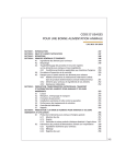
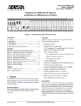
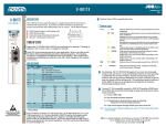
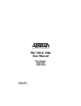
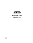
Section 61175012L1-5D
Issue 4, July 2000
CLEI Code # SIUXJKAB_ _
Total AccessTM 750 Bank Controller Unit
TA 750 BCU
Installation and Operation
CONTENTS
1. GENERAL ................................................................... 1
2. INSTALLATION/OPERATION .................................. 2
3. OPTIONS ..................................................................... 2
4. TESTING ..................................................................... 4
5. SPECIFICATIONS ....................................................... 5
6. MAINTENANCE ......................................................... 5
7. WARRANTY AND CUSTOMER SERVICE .............. 5
Figures
Figure 1. TA 750 BCU ...................................................... 1
Figure 2. Bantam Jack Monitoring Points ........................ 4
Figure 3. DB-9 Connector Pinout ..................................... 5
Tables
Table 1.
Table 2.
Table 3.
Table 4.
Table 5.
Features
The TA 750 BCU, part number 1175012L1, includes
the following features:
•
•
A
D
M
I
N
T
E
S
TXT
DS1
M
O
N
NETWORK
RX
T1
TX
RX
Compliance Codes ............................................ 2
DIP Switch S1 Options ...................................... 3
Pinout Connectors for RJ-48 T1 Interface ........ 4
LED Indication .................................................. 4
Specifications .................................................... 5
Revision History
This document has been revised to include Windows
Hyperterminal PASSWORD information, and update
Switch settings.
•
•
•
1175012L1
M
O
N
1. GENERAL
This practice provides installation and operation
procedures for the ADTRAN Total AccessTM 750
Bank Controller Unit (BCU) common module, List 1.
The TA 750 BCU module is designed specifically for
the ADTRAN Total Access 750 and is not used in any
other product. Figure 1 is an illustration of the TA
750 BCU.
•
BCU
Controls all common equipment and access
modules.
T1 network termination.
Built-in Channel Service Unit (CSU).
Provides VT 100 craft interface via faceplate
DB-9 connector.
Bantam Jacks provide access to Network T1.
LED network status indication.
61175012L1-5D
DS1
Figure 1. TA 750 BCU
•
•
•
•
T1 performance monitoring.
Supports TR-08 signaling.
UL 1950 compliant.
Meets NEBS Level 3 requirements.
General Description
The TA 750 BCU is a common module plug-in unit
designed for the TA 750. The BCU, with a built-in
CSU, provides all control functions for the TA 750
common units and all individual access modules. A
faceplate ADMIN DB-9 provides access for a VT 100
terminal for screen menu provisioning, and bantam
test jacks provide, transmit, and receive monitoring.
An additional TEST DB-9 provides timing for DS0
test equipment. A network LED shows status
information for the network T1. The unit is comprised
of a main circuit board and daughter card and inserts
directly in the BCU slot on the TA 750 shelf. An 8position DIP switch is mounted on the daughter card
and is used for T1 provisioning and clocking.
This device complies with Part 15 of the FCC rules.
Operation is subject to the following two conditions:
(1) This device may not cause harmful interference,
and (2) this device must accept any interference
received, including interference that may cause
undesired operation.
Trademarks: Any brand names and product names included in this document are
61175012L1-5,
Issue
4 respective holders.
trademarks, registeredSection
trademarks,
or trade names
of their
1
Changes or modifications not expressly approved by
ADTRAN could void the user's authority to operate
this equipment.
Functional Description
The TA 750 BCU provisions, operates, monitors, and
tests all TA 750 access modules including Quad FXS,
Quad FXO, OCU DP, DS0 DP, and Nx56/64 DSU
DP. The BCU programs T1 bandwidth use between
the various access modules and data ports.
2. INSTALLATION/OPERATION
C A U T I O N !
SUBJECT TO ELECTROSTATIC DAMAGE
OR DECREASE IN RELIABILITY.
HANDLING PRECAUTIONS REQUIRED.
After unpacking the unit, inspect it for damage. If
damage is noted, file a claim with the carrier, then
notify ADTRAN Customer Service, see section 7.
The TA 750 BCU plugs directly into the BCU slot in
the common module area of the TA 750 chassis. To
insert, hold the unit by the faceplate while supporting
the bottom side. Align the card edges to the guide
grooves for the designated slot. Insert into the chassis
until the edge connector seats firmly into the
backplane. Lock the unit in place by pushing in on
the locking lever.
Compliance Codes
This product is intended to be installed in products
providing Type "B" or "E" enclosure, and in a
Restricted Access Location. Refer to Table 1.
Table 1. Compliance Codes
Code
Input
Output
PC
TC
IC
C
–
A
C
X
–
3. OPTIONS
The TA 750 BCU can be provisioned from either an
8-position Dual In-line Package (DIP) switch (S1)
mounted on the PCB, or through screen menus
accessed via the faceplate craft interface port. Basic
T1 provisioning, clock source, and CSU loopback
options are found on the DIP switch. Refer to
Table 2 for DIP switch S1 provisioning information.
Additional and more in-depth provisioning options for
the BCU as well as access modules are available
through the craft ADMIN interface.
2
DIP switch S1 must be provisioned while the BCU is
withdrawn from the chassis. Once installed, any
software provisioning made will override the DIP
switch settings. If the unit is withdrawn and
reinserted (power cycled) the software options remain
in effect. If a DIP switch setting is changed while
withdrawn then the new DIP switch setting takes
effect. If none of the DIP switch settings were
changed then the unit will be provisioned for the last
software settings.
Electronic Provisioning
The ADMIN interface on the TA 750 BCU is used to
change factory selected options and obtain access
module status through menu screens. To access the
menu screens, connect a VT 100 terminal or computer
running a terminal emulation program to the craft
interface port using a standard male-to-female RS-232
DB-9 cable. Craft port settings are as follows:
•
•
•
•
9600 Baud
No parity
8 Data bits
1 Stop bit
CAUTION
The BCU retains provisioning setup when
removed from the chassis. If inserted into
another chassis, the provisioning setup is
invoked on that chassis' access modules.
WINDOWS HYPERTERMINAL
Windows Hyperterminal can be used as a VT 100
terminal emulation program. Open Hyperterminal by
selecting PROGRAMS / ACCESSORIES /
HYPERTERMINAL. Refer to the Help section of
Hyperterminal for additional questions.
NOTE
To ensure proper display background in
Windows Hyperterminal, select VT 100
terminal emulation under SETTINGS.
PASSWORD
Upon initial connection, the password option is
factory disabled. To enable the password, select Bank
Controller (1)/ Password Control (8) /Enable
Password (2). The factory default is PASSWORD in
all capital letters. The password can be changed to a
user-selected password if desired. If the password is
Section 61175012L1-5, Issue 4
61175012L1-5D
enabled, after approximately eight minutes of
keyboard inactivity, the terminal times out and returns
to the password login screen.
MENU NAVIGATION
To traverse through the menus, select the desired entry
and press ENTER. To work backwards in the menu
press the ESC (escape) key.
Connections
All TA 750 BCU connections are made through the
backplane connector. With the exception of power
and the V.35 connector, all of the TA 750 rear panel
connectors terminate on the BCU. These include
Network T1, Clock source, Alarms, Fractional T1, and
Management. Refer to the TA 750 Chassis Installation
and Maintenance Practice, part number 61175001L15, for additional information on rear panel
connections. Table 3 describes the T1 pinout
connections.
Faceplate LED
The faceplate network LED labeled NETWORK T1
provides status information for the network T1 using a
color coded message format. Refer to Table 4.
Table 2. DIP Switch S1 Options
Switch
Function
S1-1 ............ Framing Format
S1-3 ............ TR-08 Signaling
Description
S1-1
Off
On
Off
On
S1-3
Off
Off
On
On
Setting
ESF*
SF
TR-08 Digroup A
TR-08 Digroup B, C, or D
S1-2 ............ Line Code Format ..... Enables Bipolar Eight-Zero Substitution (B8ZS) which allows for Clear Channel
operation for the T1 carrier system, or Alternate Mark Inversion (AMI). This option
must be configured identically with all other T1 network equipment on this circuit.
On ............... AMI
Off * ............B8ZS
S1-4 ............ CSU Loopback ......... Enables the CSU Loopback Function. Unit will respond to CSU loopback sent from a
remote network device or test equipment.
Off * ............Enabled
On ............... Disabled
Timing Mode ............ Determines clock source for TA 750.
S1-5 ............ Timing A
S1-5
S1-6
Function
S1-6 ............ Timing B
Off * Off * Loop timing: Derives timing from T1
On
Off
External timing: Derives timing from external BITS clock
Off
On
Local timing: Clock generated from internal timing source
On
On
Loop timing: Derives timing from T1
DS1 Attenuation........Selects attenuation to set receiver sensitivity in decibels (dB).
S1-7 ............ LBO A
S1-7
S1-8
Setting
S1-8 ............ LBO B
Off * Off * 0 dB / 0-133 ft (LBO)
On
Off
-7.5 dB
Off
On
-15 dB
On
On
-22.5 dB
(Note: additional LBO settings can be provisioned through the menu interface.)
* Denotes factory default settings.
61175012L1-5D
Section 61175012L1-5, Issue 4
3
Table 3. Pinout Connectors for RJ-48 T1
Interface
PIN
NAME
1
R1 - RING1
Receive data from
Network DS1
2
T1 - TIP1
Receive data from
Network DS1
3
UNUSED
-
4
R - RING
Transmit data to
Network DS1
5
T - TIP
Transmit data to
Network DS1
6, 7, 8
UNUSED
4. TESTING
The TA 750 BCU provides a variety of test options
for both the Network T1 and DS0 access modules.
The faceplate of the BCU provides a bantam jack for
local T1 test access. DS0 test access for the digital
access modules (OCU DP, DS0 DP, U-BR1TE) is
provided via bantam jacks on the faceplate of each
unit.
DESCRIPTION
Faceplate Bantam Jack
The faceplate bantam jack provides a means to
monitor the network T1 connected to the rear of the
TA 750 chassis. The jacks accept standard 310-type
bantam plugs. Figure 2 displays where the bantam
jacks monitor the T1.
-
Table 4. LED Indication
LED
Network
T1
Condition
Description
Off: No power.
Red: Unit in Red Alarm (T1
down or not connected).
Yellow: Receiving Yellow Alarm
(far end unit in Red alarm).
Green: Normal Operation.
Flashing Green: Network T1 in Test.
Faceplate TEST connector
The faceplate DB-9 female TEST connector provides
the necessary clock output required by standard DS0
Logic Test equipment such as a TPI 108/109 test set.
Specifically, the TEST connector outputs 8 kHz and
64 kHz clock reference signal. Figure 3 illustrates the
DB-9 TEST connector.
DS0 test equipment is used to test DS0 access
modules such as the OCU DP, DS0 DP, or U-BR1TE.
Once the test equipment is connected to the reference
clock source, individual tests can be performed on
DS0 access modules using the faceplate bantam jacks
on each unit.
Receiver Circuitry
T1 T1
RX
PAIR R1
Clock and Data
Recovery
Line Format
Decoder
To
Backplane
DJAT
Line Format
Encoder
From
Backplane
MON IN
Test Jack
T1 T
TX
PAIR R
Equalizer
Transmitter Circuitry
MON OUT
Test Jack
Local
Loopback
Point
Line
Loopback
Point
Payload/CSU
Loopback
Point
Figure 2. Bantam Jack Monitoring Points
4
Section 61175012L1-5, Issue 4
61175012L1-5D
6
TEST
7
8
9
6. MAINTENANCE
The TA 750 BCU does not require routine
maintenance for design operation.
1
+5 V
2
GND
3
64 kHz
4
8 kHz
5
Figure 3. DB-9 Connector Pinout
T1 Loopbacks
The TA 750 supports several T1 loopbacks via the
craft interface. These loopbacks include:
•
•
•
Initiating a remote payload or line loopback
command (ESF mode only).
Responding to a remote payload or line
loopback command (ESF mode only).
Responding to a remote CSU loopback
command.
ADTRAN does not recommend that repairs be
attempted in the field. Repair services are obtained
by returning the defective unit to ADTRAN Customer
Service department.
7. WARRANTY AND CUSTOMER SERVICE
ADTRAN will replace or repair this product within
10 years from the date of shipment if it does not meet
its published specifications or fails while in service
(see: ADTRAN Carrier Networks Equipment
Warranty, Repair, and Return Policy and Procedure,
document: 60000087-10A).
Contact Customer And Product Service (CAPS) prior
to returning equipment to ADTRAN. For service,
CAPS requests, or further information, contact one of
the following numbers:
Figure 2 displays where the various loopbacks occur
in the TA 750 BCU circuitry.
Part Number
1175012L1
Self Test
The BCU goes into self test when inserted into an
active TA 750 chassis. The self test checks internal
BCU circuitry. A failed test causes the faceplate
Network T1 LED to blink red.
ADTRAN Sales
Pricing/Availability
(800) 827-0807
5. SPECIFICATIONS
Refer to Table 5 for TA 750 BCU specifications.
ADTRAN Technical Support
Presales Applications/Postsales Technical Assistance
(888) 4-ADTRAN
Standard hours: Monday-Friday, 7 a.m. - 7 p.m. CST
Emergency hours: 7 days/week, 24 hours/day
ADTRAN Repair/CAPS
Return for Repair/Upgrade
(256) 963-8722
Table 5. Specifications
Mechanical
Size: 1 11/16" W x 3" H x 10"L
Weight: 1 lb.
Environmental
Repair and Return Address
ADTRAN, Inc.
CAPS
Operating Temperature: -40º to 65º C
Storage Temperature: -40º to 85º C
Relative Humidity: Up to 95% non-condensing
Configuration Codes
Power Code (PC): IN: F, OUT: C
Telecommunication Code (TC): IN: X, OUT: X
Installation Code (IC): IN: A, OUT: -
61175012L1-5D
Section 61175012L1-5, Issue 4
5