1
Chapter 4 — Theory of Operation
Bus I/F
Scanner I/F
SDBUF_D7..0
DMA
BUFFER
FIFO
SA25..0
SCAN_DREQ
Host CPU
I/F
DQM3..0
nOE
nWE
nPWE
RDY
RD/WR
FPGA_CS
PCI/HCR_CS
ADDR DECODE,
RD/WR CTL
SCAN_IRQ
IRQ
CTL
IMAGE
CAPTURE
STATE
MACHINE
CTL
REGs
BLUR
DETECT,
EXPOSURE
SENSE
DBP
COUNT
LOGIC
GPIO
Kypd
IO MUX LOGIC
SD31..0
DBP_HSYNC
Scanner
SOS_VSYNC
TETH_DBP, SOS
I/F
TETH_PRESENT
ILLUM_LASEN_RTS
SPEED_RANGE_GDRD
SCAN_FLASH_EN
SCAN_TRIG*
IMAGER_PIXCLK
SCAN_LED
SCAN_LED_LOW
USER_LED<2:1>
DOCK_TRIG*
VOL<2:0>
GPIO
KEY_RET<7:0>
HCR_WR2*
HCR_WR5*
PCI
CTL
REGs
BUS
ARBITER
BATT_FAULT_IRQ
REQ#, GNT#
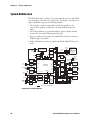
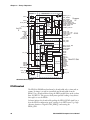
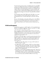
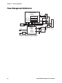
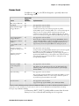
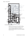
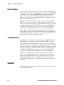
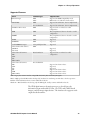
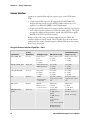
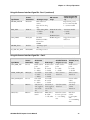
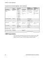
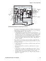
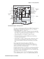
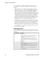
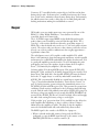
CK30 FPGA Block Diagram-Count Gathering for 1D Scanners
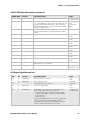
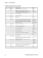
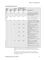
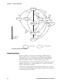
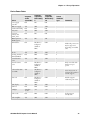
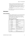
The scanner is enabled and controlled from the PXA255 through memorymapped registers in the FPGA and octal register U11 (see the “Using the
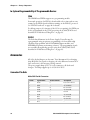
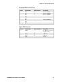
Scanner Interface Signal Set” table on page 76):
• SCAN_PWR_EN* is asserted low to switch 3.3V and 5V power
through high-side switches U12 and U13 to scanner connector J3. The
scan flex is used to select the voltage appropriate to the installed scanner.
The selected voltage is also routed through a loop-back on the flex to
provide the appropriate pull-up voltage (SCAN_VCC) for signals from
open-collector scanner outputs (like SCAN_TRIG*, DBP_HSYNC,
and SOS_VSYNC).
Most scanners are powered up only when scanning is commanded, but
tethered scanners are powered continuously while the CK30 is on so that
their triggers will work.
• SCAN_FLASH_EN* is asserted low to enable the scanner and/or start
its dither mirror.
• ILLUM_LASEN_RTS is asserted low to enable the laser or scanner
illumination.
• SCAN_TRIG* is set high or low depending on the scanner. This is a
general-purpose control line used for spotter beam control, scan speed
selection, scanner reset, or tethered scanner auto-detect enable,
depending on the installed scanner (See “Using the Scanner Interface
Signal Set” on page 76).
CK30 Handheld Computer Service Manual
79