1
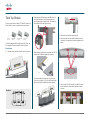
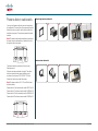
T3 System Assembly Guide Telepresence T3 System Assembly Guide 78-19803-02 Cisco TelePresence System T3 System Assembly Guide, December 2011 Page 1 of 28 What’s in this document? Related documents.............................................................................................................................................................................3 Tools needed............................................................................................................................................................................................3 Where will the different units reside when everything is assembled?...................................................4 Bottom modules & monitors........................................................................................................................................................5 Leveling the systems..........................................................................................................................................................................9 Table columns installation.............................................................................................................................................................9 Table Top Module...............................................................................................................................................................................10 Power outlets in cable wells...................................................................................................................................................... 11 Cameras and codecs.....................................................................................................................................................................12 Splitter bracket.....................................................................................................................................................................................12 TCU, Splitter and Switch..............................................................................................................................................................13 System connections........................................................................................................................................................................14 Where to put cable bundling kits A & 1–3 ...................................................................................................................15 Details of cable bundling kits A & 1–3 .............................................................................................................................16 Where to put cable bundling kits 4–8 .............................................................................................................................17 The objective of this documentation is to provide the reader with assistance in using and configuring the product. The specifications for the product and the information in this Guide are subject to change at any time, without notice, by Cisco. Every effort has been made to supply complete and accurate information in this Guide; however, Cisco assumes no responsibility or liability for any errors or inaccuracies that may appear in this document. All trademarks used in this document are the property of their respective holders. This Guide may be reproduced in its entirety, including all copyright and intellectual property notices, in limited quantities in connection with the use of this product. Except for the limited exception set forth in the previous sentence, no part of this Guide may be reproduced, stored in a retrieval system, or transmitted, in any form, or by any means, electronically, mechanically, by photocopying, or otherwise, without the prior written permission of Cisco. www.cisco.com © 2010–2011 Cisco Inc. Details of cable bundling kits 4–8 ......................................................................................................................................18 Where to put cable bundling kits 9–11 ...........................................................................................................................19 Details of cable bundling kits 9–11 ....................................................................................................................................20 Where to put cable bundling kits 12–21 .......................................................................................................................21 Details of cable bundling kits 12–16..................................................................................................................................22 Details of cable bundling kits 17–21..................................................................................................................................23 Presentation monitors and cable wells...........................................................................................................................24 Lids and cover plates......................................................................................................................................................................25 Optional pockets for cleaning kit and docs.................................................................................................................26 78-19803-02 Cisco TelePresence System T3 System Assembly Guide, December 2011 Page 2 of 28 Related documents What has changed? Tools needed The following documents are also available: General: You will need the following tools and equipment when assembling the system: • • • • • • • T3 Room Recommendations Guide 119076 Maintenance Guide: 78-19801 Cable Schematics: 78-19798 Room Installation Guide: 78-19802 Quick User Reference Guide: 78-19804 Document Camera Assembly Guide: 78-19800 Ceiling Lights Assembly Guide: 78-19799 With the exception of the Room Recommendations Guide all of these documents are supplied with the Systems they describe. Should you nevertheless need any of these documents, contact your Cisco partner. • • • • • The removal of the splitter in the left system bottom module has caused changes in the cabling structure descriptions. This is reflected in revised cable structure drawings and corresponding tables. The presentation monitor assembly installation procedure has been changed in this version. Revised description of bottom module assembly procedure. Recommended sequence is to start with the innermost (the right) module—as viewed from the recommended door location. It used to be the left module. Ceiling light assembly is now moved to a separate document. Document camera installation is now a separate document Additions, changes and updates • • • • • • • • • • • • • • • 78-19803-02 Cisco TelePresence System T3 System Assembly Guide, December 2011 Illustrations showing the need for keeping the distance between the table and the rear wall at 130 cm. Fastening the left bottom module. Drawing describing splitter bracket mounting in right bottom module. Drawing showing revised floor cabling structure. Drawings showing monitors when mounting now shows monitors without grilles attached. Drawing showing revised system cabling structure. Drawing showing how the TCU is mounted in left table column. Drawing showing revised table cabling structure. Description of the presentation monitor assembly installation. Fire enclosure for document camera associated equipment. Drawing showing document camera location. Change in the document camera cabling. Description of document camera installation. Trip lists are now an integral part of the cover plates and need no mounting description. Drawing of the cover plates. • • • • • • • • • • • • • • • • • • • Spirit Level (bubble level) for light installation and monitor levelling. 13 mm open end/box wrench to fasten bottom module to steel structure, columns to steel structure, table to columns. 10 mm open end wrench to fasten floor structure center to left/right, adjusting table top tighteners, codec brackets to bottom module, adjusting TCU, Splitter, Switch and Power brackets, cleaning kit and doc pockets, fasten center cover plates. 1 ⁄4” ratchet wrench 1 ⁄4” socket extension 13 mm deep socket to fasten table column to steel structure and to fasten the table. 10 mm socket to fasten splitter to bottom module, adjust center door bottom module and fasten table to columns. 7 mm socket to dismount screws in bottom module and monitors (preparing for angle plate between screens). 5 mm Allen bit for height adjustment of monitor systems. 4 mm Allen bit to removing cable hatches in bottom module, fasten center cover plates. 3 mm Allen bit to mount angle plate between screens. 2.5 mm Allen bit to dismount screws in bottom module and monitors (preparing for angle plate between screens)and dismount/mount column covers. 2 mm Allen wrench for cable clamps in cable wells. Torx T10 to fasten codec brackets to codecs, fasten cleaning kit and doc pockets. Torx T20 to fasten power outlet brackets in cable wells. Portable drill Hammer for cable wells power outlets (if installation is to be done). Blade screwdriver for cable wells power outlets (if installation is to be done). 1 ⁄4” deep socket to fasten cable wells power outlets to the brackets (if installation is to be done). Page 3 of 28 Where will the different units reside when everything is assembled? Presen t Splitteation rR Splitte r AC/D C Codec C Codec L Camer Camera Camer a Left Presentation Monitor Power outlet L1 Codec Center Presentation Monitor Power outlet L2 Left Presentation monitor AC/DC TCU 78-19803-02 Cisco TelePresence System T3 System Assembly Guide, December 2011 Power outlet C1 R a Right Presentation Monitor Power outlet C2 Power outlet R1 Center Presentation monitor AC/DC Right Presentation monitor AC/DC Power outlet R2 Splitter AC/DC Switch AC/DC Splitter Switch Page 4 of 28 Bottom modules & monitors Unpack the box marked “T3 Floor structure and columns”. The box contains the parts shown below. Items are not shown to scale. Right system cover plate r Center cover plate (II) Note! The system has been designed for rooms with entrance door opening outwards. Should you for any reason be unable to fulfill this requirement, make sure you position the system so that it will not block the door from opening completely. Note! The distance between the table and the rear wall of the room should not exceed 130 cm (4’ 3”) as this will affect the perceived immersive room quality (the other side should see nothing but blue walls, avoiding any sidewalls coming into view): Rig pla ht c te ove Center cover plate(I) Left system cover plate Do as follows: 1. Begin by placing the center bottom frame centered on the floor, approximately 4.2 m (13’ 9”) from the rear (white) wall. The distance between the white and the blue wall is 140 mm (5½”). Observe the 130 cm requirement (see the below right sidebar). D o or Le pla ft co te v er 4.06 m 13’31⁄2” Center bottom frame 2. Unpack the bag containing screws, nuts and plates, located in the Accessories box. Contents should be as shown on the next page. Left bottom frame Module angle plate (2×) a) Distance to rear wall is 130 cm (4’ 3”) Right bottom frame Cleaning kit pocket Splitter bracket b) Distance has been increased to 155 cm (5’) Nut plate (8×) Cable channel (2×) Document pocket Codec bracket (3×) Splitter power supply bracket In addition the box contains the two table columns (not shown). These shall be installed later. Put them aside right now. 78-19803-02 Cisco TelePresence System T3 System Assembly Guide, December 2011 c) Distance has been increased to 180 cm (6’) Page 5 of 28 3. Then place the right bottom frame on the right side of the center bottom frame. Fasten with 4 nuts type M6. Repeat for left side. The screws, nuts and plates 4. Make sure that the distance to the wall is constant. If necessary, mark the position with a piece of tape or similar. = Tape 78-19803-02 Cisco TelePresence System T3 System Assembly Guide, December 2011 Page 6 of 28 5. Unpack the first system and take out the bottom module. Unscrew the top screw on the left side in addition to the cable hatch cover. 7. Insert the right DNAM cable 117856 and attach it to the right DNAM module, as shown, This must be done before the monitor is mounted onto the bottom module. Once the monitor is mounted, cable insertion will become very difficult. The DNAM cable 117856 is located in the accessories kit. 8. Unpack the monitor assembly and lift it onto the bottom module. It requires a minimum of four persons to lift the assembly, using the attached straps and gloves. Local codes may require more persons. Caution! Make sure you hold the monitor level, otherwise one of the straps may slip. 6. Attach the module to the floor structure—making it become the right bottom module—by means of 4 nuts type M8, as shown. Caution! Make sure the grilles have not been mounted when you do this! 9. Remove the screw on the monitor, as shown. 78-19803-02 Cisco TelePresence System T3 System Assembly Guide, December 2011 Page 7 of 28 10.Unpack the next bottom module. Unscrew the top screw and the cable hatch cover on both sides of the module. 13.Unpack the next monitor assembly and remove the top side screw on both sides of the monitor. 16.Mount the left bottom module onto the floor structure. 14.Mount the center monitor onto the center bottom module. 17. Insert the left DNAM cable 117850 and attach it to the left DNAM module in a way similar to what was done to the center and right bottom modules, This must be done before the monitor is mounted onto the bottom module. Once the monitor is mounted, cable insertion will become very difficult. 11. Mount the center bottom module onto the floor structure. The DNAM cable 117850 is located in the Accessories kit. 15.Unpack the third bottom module. Unscrew the top screw and the cable hatch cover on the right side of the module. 12.Insert the center DNAM cable 117852 and attach it to the center DNAM module in a way similar to what was done to the right bottom module, This must be done before the monitor is mounted onto the bottom module. Once the monitor is mounted, cable insertion will become very difficult. 18.Unpack the final monitor assembly and remove the top side screw on right side of the monitor. 19. Mount the left monitor onto the left bottom module. The DNAM cable 117852 is located in the accessories kit. 78-19803-02 Cisco TelePresence System T3 System Assembly Guide, December 2011 Page 8 of 28 Leveling the systems Table columns installation 1. In order to level the systems, use 4 pcs of the M10×30 screw in the holes marked in the picture below for each bottom module. Loosen nuts before adjusting the pin bolts down. When proper adjustment has been done, tighten nuts again. You may want to open the lid completely when doing this—observe the tip on page 15. 1. Remove the door of the table column while the column is still in the box. Then take the column out of the box. Remove the cover as shown below. The column covers and the doors shall not be mounted yet, so we recommend that you put them in a place where they will not become subject to damage. 2. Unpack the 2 angle plates and the 8 nut plate for angle plates from the box marked “T3 Floor structure and columns”. Fasten with M4 × 14 screws through the holes on top side on the monitors and with M4 ×40 screws and washers through the holes of the bottom modules. Use the short screw at the monitor top and the long screw at the bottom module top. Use the shims plates inside the angle plate. Note that the top cover and the door must be opened in order to do so. The columns are not identical, place the one marked left to the left and the one marked right to the right. See the following page for a definition of left and right. Bottom module 2. Mount the columns using 12 × nut M8 (Captive washer nut) for each column (24 altogether). Keys for the door locks can be found in the protective foam in the table column box. 78-19803-02 Cisco TelePresence System T3 System Assembly Guide, December 2011 Page 9 of 28 Table Top Module Carefully unpack the box labeled “T3 Table Top”, where you will find the left-, center- and right table top assemblies. 2. Fasten two nuts (M8) and one screw M8×16 in each joint of the table tops. Start by fastening the nuts pointing towards the system (1 & 2). Then fasten the other screws (3). Screw finger tight only. 5. Repeat for the other table top module (3). Table top tighteners Right table top assembly Center table top assembly Left table top assembly You will also need the table top tighteners (left). There are four altogether. These are located in the kit of screws. 1 2 6. Adjust the table modules slightly, if needed, to obtain the best fit, then apply the four table top tighteners, as shown. 3 Do as follows: 1. Slide the center table top assembly into both columns. 3. When assembling the table, you will need the 120774 Lamells and the table top tighteners, as shown. 4. Tilt the center table top assembly (1) by lifting the “chair-side” of it slightly (<5°) and slide the right table (2) top so that the steel profile holds them together. 3 Overview 7. Fasten using 16 pcs M6 nut and 4 pcs M8×16 screws, as indicated by the circles below. Tighten all screws and nuts. 1 2 System Table Left Right 78-19803-02 Cisco TelePresence System T3 System Assembly Guide, December 2011 Page 10 of 28 Power outlets in cable wells You may install power outlets for personal computers in the cable wells. The exact look of the power outlet socket itself will be country-specific, but this will not affect the installation procedure. The socket comes with the cable installed. Left and right monitor cable wells 1 2 3 4 3 4 5 Note! The power outlet sockets installation procedure for the center monitor cable wells is not identical to that of the right and left monitor wells. Left Center Right The power outlet kits are located in 6 boxes in the Telepresence kit. Center monitor cable wells 1 2 Follow the procedure outlined to the right. The cables shall be connected to the power distribution units as shown in the document “78-20195-01 T3 Cable Schematics”, which comes with the system. Note! The power outlets in L2, C1, C2 and R2 will need extension cables. Power outlet in L2 will use extension cable 129627 (kit 12) Power outlet in C1 will use extension cable 129628 (kit 13) Power outlet in C2 will use extension cable 129629 (kit 16) Power outlet in R2 will use extension cable 129630 (kit 17) L1 L2 C1 C2 R1 R2 78-19803-02 Cisco TelePresence System T3 System Assembly Guide, December 2011 Page 11 of 28 Cameras and codecs 7. Put cable clamps back in once all cabling has been completed. Do as follows: 1. Open the top cover. 2. Locate the camera cable. 3. Hold the camera upside down. 4. Connect the HDMI and RJ45 connectors of the camera cable. 480p60 720p50 720p60 720p30 720p25 720p60 720p50 SW control** 0 1 0 1 0 HDMI *Camera negotiates format over HDMI, HD-SDI tracks HDMI, and defaults to 1080p30 in absence of HDMI sync. **Please consult manual. HD-SDI 1080p30 1080p25 720p30 720p50 720p60 480p60 0 1 0 0 0 0 1 0 0 1 0 0 1 1 0 0 0 1 1 1 0 1 720p25 Auto* HDMI 1080p50 1080p25 1080p60 0 0 1 0 0 0 0 1 0 1 Video format 0 0 0 1 0 0 0 0 1 1 0 0 0 0 0 0 0 0 0 1 1 2 3 4 5 1080p30 RJ45 8. Repeat for the other two cameras. 9. Detach two screws on each side of the codec, as shown. 10. Mount the bracket onto the codec and screw the screws back in. The bracket can be found in the Telepresence kit. Flickering image? Some countries use a line frequency of 50Hz, while others use 60Hz. Default camera setting is for 50Hz, which will cause the image to flicker in 60Hz regions. To rectify this, set the DIP switches to 1080p60 when used in countries with 60Hz line frequency—see the table on the camera’s underside. Mounting hole (Tripod) 1/4" UNC PrecisionHD 1080p www.tandberg.com/recycling Made in Norway ( ) TTC8-02 ( ) S/N Rev 14. Shut the top cover and attach the cover and the loudspeaker grill as shown. Make sure all snaps and magnet points are securely fixed. Repeat for the two other cameras. 116606 rev.06 5. Carefully put the camera in place, then push the cable down the channel while doing this. 11. Use four M6 (Bag 4) nuts to attach the codec and the bracket to the inside of the bottom module lid. Splitter bracket Fasten the splitter bracket in the right bottom module using 2 × M6 flange nuts. Then place the HDMI splitter onto the bracket—connectors pointing downwards with the power switch to the left. Use two M6 nuts to fasten the power supply bracket and insert the power supply in the bracket just below the splitter, as shown. Split 12.Repeat for the other two codecs. 13.Connect the camera cables to the codecs as shown. 6. Locate the other end of the camera cable mounted to the monitor. Remove the cable clamps designed to fasten the cable inside the bottom module. Split ter ter b r acke t Line in Bracket for Splitter power supply Push the camera cable down the channel through the Monitor. Use the cable clamps to fasten the cable inside the Bottom Module and connect to the codec. Camera cable goes inside the channel Camera cable 78-19803-02 Cisco TelePresence System T3 System Assembly Guide, December 2011 Split te r p owe r su p p ly Page 12 of 28 TCU, Splitter and Switch Do as follows: 2. Find the TCU in the box marked “T3 Telepresence kit” and fasten the TCU to the left column, using the bracket and the same nut as were just loosened. 3. Now, loosen the two nuts shown. 1. The Telepresence Control Unit (TCU) is to be inserted in the left table column. Unscrew the nut holding the bracket (outer bracket shown in green in the below Fig.) in the left column. The TCU runs off line voltage directly and needs no further external power supply. 4. Install the power distribution block, put the nuts back and fasten them. 78-19803-02 Cisco TelePresence System T3 System Assembly Guide, December 2011 Page 13 of 28 Note! The splitter cable for the TCU found in the kit must be put aside for later use. See “Details of cable bundling kits 17–21” on page 13 for more when and where to use it. Switch Splitter 5. Unscrew the nuts holding the bracket in the right column. Turn on the Presentation input switch and the Splitter power switch before mounting. Fasten switch and splitter in the same manner as the TCU was fastened. Note the orientation of both units (shown below) Fasten the two power supplies as shown below. System connections To connect the different parts of the system, a set of readyto-use cable bundling kits come with the system. The following pages outline where to put each cable kit. Details on the connections are found in the Cabling Schematics drawing, which is located in the Cable Bundling kit box. Use the information on the following pages in combination with the Cable Schematics drawing to insert, attach and connect all cables correctly. Note! Some cables come with a color coding. For these cables blue is system end and red is table end. Note! Cable clamps inside bottom modules should be put back in place once all cabling has been completed. The power supplies for Splitter and Switch goes here 78-19803-02 Cisco TelePresence System T3 System Assembly Guide, December 2011 Page 14 of 28 Where to put cable bundling kits A & 1–3 These cables are country-specific These cables are country-specific B A B A (2 cables) 1 3 Note! All cables going from the left part towards the wall will reside under the same cover. There is one cover for the left side and on for the right side. A A (2 cables) 2 1 1 2 Caution! No cables must be put so that they end up between the floor structure and the door—they must all enter the system entirely underneath the floor structure. Otherwise the door will not close properly. B 3 Tip! When cabling and levelling the system you may want to fully open the centre bottom module lid. Note that you may either open the center module lid or both the left & right module lids fully at a time. All three lids cannot stay fully opened simultaneously. B Floor Structure Caution! If you choose to fully open any of the lids, make sure you put a soft cloth or similar underneath the lid to avoid scratches. 78-19803-02 Cisco TelePresence System T3 System Assembly Guide, December 2011 Page 15 of 28 Details of cable bundling kits A & 1–3 Drawing reference Art.no Bundling description From / to device A 118610 Powercable kit Country specific extension cords B 121544 T3 PDU Cable kit Country specific extension cords to PDU 1 117915 117916 Cable Power Male – Female 1.0m w/marking Cable Power Male – Female 2.3m w/marking Wall – Power Distribution Block Module Left Wall – Power Distribution Block Module Center 2 117909 117917 Cable Power Male – Female 1.0m w/marking Cable Power Male – Female 1.0m w/marking Wall – AC/DC for Presentation Splitter Right Wall – Power Distribution Block Module Right 3 117875 117880 Cable RJ45 – RJ45 4.8 m w/marking Cable RJ45 – RJ45 4.8 m w/marking Videonet/IP – Telepresence Control Unit Videonet – Telepresence Control Unit Note! Some cables come with a color coding. For these cables blue is system end and red is table end. 78-19803-02 Cisco TelePresence System T3 System Assembly Guide, December 2011 Page 16 of 28 Where to put cable bundling kits 4–8 Note! Pull the cables from the bottom modules gently to tighten everything, so that any excess cable lengths get collected in the table columns and nowhere else. Main Video Display C 6 6 7 6 DNAM L 4 7 Codec L 4 7 Main Video Display R 7 5 7 Codec C 8 Presentation Splitter R 7 6 8 5 8 8 8 7 DNAM R 6 DNAM C Main Video Display L Codec R T1 Systems 78-19803-02 Cisco TelePresence System T3 System Assembly Guide, December 2011 Page 17 of 28 Details of cable bundling kits 4–8 Drawing reference Art.no Bundling description From / to device 4 117831 117833 117836 117838 117842 118592 Cable HDMI - DVI-D 2,45 m w/marking Cable HDMI - HDMI 2,5 m w/marking Cable RCA - RCA 2,5 m w/marking Cable RCA - RCA 2,5 m w/marking Cable HDMI - HDMI 2,35 m w/marking Cable RJ45 - RJ45 2,45 m w/marking Codec L - Codec C Codec L - Codec C Codec L - Codec C Codec L - Codec C Codec L - Codec C Codec L - Codec C 5 117834 117835 117837 117839 117843 118591 Cable HDMI - HDMI 2,5 m w/marking Cable HDMI - HDMI 2,5 m w/marking Cable RCA - RCA 2,5 m w/marking Cable RCA - RCA 2,5 m w/marking Cable HDMI - HDMI 2,5 m w/marking Cable RJ45 - RJ45 2,45 m w/marking Codec R - Codec C Codec R - Codec C Codec R - Codec C Codec R - Codec C Codec R - Codec C Codec R - Codec C 6 117860 129485 129486 129487 129612 Cable HDMI - HDMI 3,2 m w/marking Cable Power Male - Female 0,5m w/marking Cable Power Male - Female 0,8m w/marking Cable Power Male - Female 0,6m w/marking Cable DVI-D - HDMI cable 1,0 m w/marking Codec L - Presentation Splitter Right Power Distribution Block Module Left - Main Video Display L Power Distribution Block Module Left - Codec L Power Distribution Block Module Left - DNAM L Codec L - Main Video Display L 7 117841 117854 129485 129486 129487 129612 129613 Cable DVI-D - HDMI 1,65 m w/marking Cable RCA - Split 2,5m w/marking Cable Power Male - Female 0,5m w/marking Cable Power Male - Female 0,8m w/marking Cable Power Male - Female 0,6m w/marking Cable DVI-D - HDMI cable 1,0 m w/marking Cable RCA - RCA 0,76 m w/marking Codec C - Presentation Splitter Right Codec C - DNAM L/R Power Distribution Block Module Center - Main Video Display C Power Distribution Block Module Center - Codec C Power Distribution Block Module Center - DNAM C Codec C - Main Video Display C Codec C - DNAM C 8 117858 129485 129486 129487 129612 Cable HDMI - HDMI 1,1 m w/marking Cable Power Male - Female 0,5m w/marking Cable Power Male - Female 0,8m w/marking Cable Power Male - Female 0,6m w/marking Cable DVI-D - HDMI cable 1,0 m w/marking Codec R - Presentation Splitter Right Power Distribution Block Module Right - Main Video Display R Power Distribution Block Module Right - Codec R Power Distribution Block Module Right - DNAM R Codec R - Main Video Display R Note! Some cables come with a color coding. For these cables blue is system end and red is table end. 78-19803-02 Cisco TelePresence System T3 System Assembly Guide, December 2011 Page 18 of 28 Where to put cable bundling kits 9–11 9 10 11 10 10 9 9 11 Caution! No cables must be put so that they end up between the floor structure and the door—they must all enter the system entirely underneath the floor structure. Otherwise the door will not close properly. 9 10 11 Floor Structure 78-19803-02 Cisco TelePresence System T3 System Assembly Guide, December 2011 Page 19 of 28 Details of cable bundling kits 9–11 Drawing reference Art.no Bundling description From / to device 9 117806 117866 117867 117868 129614 129618 129619 Cable HDMI - HDMI 5,6 m w/ marking Cable 9p DSUB - 9p DSUB 2,45 m w/marking Cable 9p DSUB - 9p DSUB 3,9 m w/marking Cable 9p DSUB - 9p DSUB 5,45 m w/marking Cable 3,5 plug split RCA/RCA 4,0 m w/marking Cable XLR - XLR 4,85 m w/marking Cable XLR - XLR 4,8 m w/marking Presentation Splitter Right - Touch Collaboration Display L Telepresence Control Unit - Main Video Display L Telepresence Control Unit - Main Video Display C Telepresence Control Unit - Main Video Display R Telepresence Control Unit - Codec C Mic L1 - Codec C Mic L2 - Codec C 10 117869 117870 117871 117876 117877 117878 Cable 9p DSUB - 9p DSUB 2,6 m w/marking Cable 9p DSUB - 9p DSUB 4,0 m w/marking Cable 9p DSUB - 9p DSUB 5,75 m w/marking Cable RJ45 - RJ45 2,7 m w/marking Cable RJ45 - RJ45 4,15 m w/marking Cable RJ45 - RJ45 5,75 m w/marking Telepresence Control Unit - Codec L Telepresence Control Unit - Codec C Telepresence Control Unit - Codec R Telepresence Control Unit - Codec L Telepresence Control Unit - Codec C Telepresence Control Unit - Codec R 11 117809 117812 117828 117829 129615 129616 129617 129620 129621 Cable HDMI - HDMI 5,0 m w/marking Cable HDMI - HDMI 3,5 m w/marking Cable XLR plug - XLR plug 4,2 m w/marking Cable XLR plug - XLR plug 4,2 m w/marking Cable DVI - DVI 4,2 m w/marking Cable XLR - XLR 6,1 m w/marking Cable XLR - XLR 6,0 m w/marking Cable XLR - XLR 4,85 m w/marking Cable XLR - XLR 4,8 m w/marking Presentation Splitter Right - Touch Collaboration Display C Presentation Splitter Right - Touch Collaboration Display R Presentation Input Switch - Codec C Presentation Input Switch - Codec C Presentation Input Switch - Codec C Mic C1 - Codec C Mic C2 - Codec C Mic R1 - Codec C Mic R2 - Codec C Note! Some cables come with a color coding. For these cables blue is system end and red is table end. 78-19803-02 Cisco TelePresence System T3 System Assembly Guide, December 2011 Page 20 of 28 Where to put cable bundling kits 12–21 21 21 12 15 21 21 21 21 13 16 21 21 21 19 14 17 21 21 20 12 12 13 13 C 19 21 14 16 18 17 16 20 18 17 15 19 Left Right Left Right The table is shown as seen from the “chair-side” of the table (towards the system). 78-19803-02 Cisco TelePresence System T3 System Assembly Guide, December 2011 Page 21 of 28 Details of cable bundling kits 12–16 Drawing reference Art.no Bundling description From / to device 12 117807 117862 117881 117882 129627 129633 Cable USB A - USB B 1,1 m w/marking Cable 9p DSUB - 9p DSUB 1,0 m w/marking Cable RJ45 - RJ45 0,7 m w/marking Cable RJ45 - RJ45 0,5 m w/marking Cable Power Male - Female 0,75m w/marking Cable Power Male - Female 0,5m w/marking Telepresence Control Unit - Touch Collaboration Display L Telepresence Control Unit - Touch Collaboration Display L Telepresence Control Unit - PC connectivity Feedthrough L1 Telepresence Control Unit - PC connectivity Feedthrough L2 Power Distribution Unit 1 - Power Outlet L2 Power Distribution Unit 1 - AC/DC for Touch Collaboration Display L 13 117810 117863 117883 117884 129628 Cable USB A - USB B 2,0 m w/marking Cable 9p DSUB - 9p DSUB 1,95 m w/marking Cable RJ45 - RJ45 1,7 m w/marking Cable RJ45 - RJ45 1,95 m w/marking Cable Power Male - Female 1,3m w/marking Telepresence Control Unit - Touch Collaboration Display C Telepresence Control Unit - Touch Collaboration Display C Telepresence Control Unit - PC connectivity Feedthrough C1 Telepresence Control Unit - PC connectivity Feedthrough C2 Power Distribution Unit 1 - Power Outlet C1 14 117813 117864 117885 117886 Cable USB A - USB B 3,5m w/marking Cable 9p DSUB - 9p DSUB 3,35 m w/marking Cable RJ45 - RJ45 3,15 m w/marking Cable RJ45 - RJ45 3,45 m w/marking Telepresence Control Unit - Touch Collaboration Display R Telepresence Control Unit - Touch Collaboration Display R Telepresence Control Unit - PC connectivity Feedthrough R1 Telepresence Control Unit - PC connectivity Feedthrough R2 15 117805 117814 117815 117820 117821 Cable HDMI - HDMI 3,9 m w/ marking Cable DVI - DVI 4,8m w/marking Cable DVI - DVI 4,6m w/marking Cable 3,5 plug - 3,5 plug 4,55 m w/marking Cable 3,5 plug - 3,5 plug 4,4 m w/marking Touch Collaboration Display Splitter - Touch Collaboration Display L PC connectivity L1 - Presentation Input Switch PC connectivity L2 - Presentation Input Switch PC connectivity L1 - Presentation Input Switch PC connectivity L2 - Presentation Input Switch 16 117808 117816 117817 117822 117823 118567 129629 Cable HDMI - HDMI 2,20 m w/marking Cable DVI - DVI 3,35 m w/marking Cable DVI - DVI 3,1 m w/marking Cable 3,5 plug - 3,5 plug 3,05 m w/marking Cable 3,5 plug - 3,5 plug 2,9 m w/marking Cable Power Male - Female 0,5m w/marking Cable Power Male - Female 0,75m w/marking Touch Collaboration Display Splitter - Touch Collaboration Display C PC connectivity C1 - Presentation Input Switch PC connectivity C2 - Presentation Input Switch PC connectivity C1 - Presentation Input Switch PC connectivity C2 - Presentation Input Switch Power Distribution Unit 2 - AC/DC for Touch Collaboration Display C Power Distribution Unit 2 - Power Outlet C2 Note! Some cables come with a color coding. For these cables blue is system end and red is table end. Note! Cables meant to be dragged out from the cable wells by the users (PC connectivity cables) should be arranged so that the cable label stickers do not become visible to the T3 users. L1 78-19803-02 Cisco TelePresence System T3 System Assembly Guide, December 2011 L2 C1 C2 R1 R2 Page 22 of 28 Details of cable bundling kits 17–21 Drawing reference Art.no Bundling description From / to device 17 117811 117818 117819 117824 117825 118570 129630 Cable HDMI - HDMI 0,8 m w/marking Cable DVI - DVI 1,9 m w/marking Cable DVI - DVI 1,6 m w/marking Cable 3,5 plug - 3,5 plug 1,55 m w/marking Cable 3,5 plug - 3,5 plug 1,35 m w/marking Cable Power Male - Female 0,5m w/marking Cable Power Male - Female 0,75m w/marking Touch Collaboration Display Splitter - Touch Collaboration Display R PC connectivity R1 - Presentation Input Switch PC connectivity R2 - Presentation Input Switch PC connectivity R1 - Presentation Input Switch PC connectivity R2 - Presentation Input Switch Power Distribution Unit 2 - AC/DC for Touch Collaboration Display R Power Distribution Unit 2 - Power Outlet R2 18 117832 117872 Cable DVI-D - HDMI 3,65 m w/marking Cable 9p DSUB - 9p DSUB 3,6 m w/marking Touch Collaboration Display Splitter - Cable 117857 Presentation Input Switch - Telepresence Control Unit 19 117873 129632 Cable RJ45 - RJ45 0,35 m w/marking Cable Power Male - Female 0,5m w/marking Telepresence Control Unit - Telepresence Control Unit Power Distribution Unit 1 - Telepresence Control Unit 20 117893 117894 Cable Power Male - Female 0,8m w/marking Cable Power Male - Female 0,8m w/marking Power Distribution Unit 2 - AC/DC for Presentation Input Switch Power Distribution Unit 2 - AC/DC for Touch Collaboration Display Splitter 21 118714 118714 118714 118714 118714 118714 Cable RJ45 RJ45 0,8 m w/marking Cable RJ45 RJ45 0,8 m w/marking Cable RJ45 RJ45 0,8 m w/marking Cable RJ45 RJ45 0,8 m w/marking Cable RJ45 RJ45 0,8 m w/marking Cable RJ45 RJ45 0,8 m w/marking PC Connectivity Feedthrough C1 - PC Connectivity C1 PC Connectivity Feedthrough C2 - PC Connectivity C2 PC Connectivity Feedthrough L1 - PC Connectivity L1 PC Connectivity Feedthrough L2 - PC Connectivity L2 PC Connectivity Feedthrough R1 - PC Connectivity R1 PC Connectivity Feedthrough R2 - PC Connectivity R2 Note! Some cables come with a color coding. For these cables blue is system end and red is table end. Tip! If you want to install an extra cable for DVD/BlueRay, this should be inserted through the rightmost well (R2). Connect the cable to Input 8 of the Switch. Use 720p max. 78-19803-02 Cisco TelePresence System T3 System Assembly Guide, December 2011 Page 23 of 28 Presentation monitors and cable wells 4. Position the assembly as shown, and lower the monitor. 7. Connect all the cables in the table as shown in the separate Cable Schematics document. Monitor power supplies Presentation monitor installation 1. Loosen the cable clamp as shown below. 5. Fig. below shows the well when viewed from underneath the table. Insert the M5 × 20 screws in pos 1 and 2 (marked with circles). Screw only finger tight. 1. The power supplies for the Center and the Right Presentation Monitors shall both reside in the right table column—see below. Make sure the Center Presentation Monitor power supply is the upper of the two. Otherwise the cable will be too short. Then use the four adjustment screws (marked with arrows) to level the monitor so that it becomes flush with the table surface, then tighten 1 and 2. Left 2. Insert the cables which are to reside in the cable wells as shown below. Pull them out as long as possible without making their labels visible to the users. Fasten the cable clamp that was loosened. Right 2. The left Presentation Monitor power supply shall reside in the left column—see below. 1 2 Center Left Right The power supplies for the presentation monitors shall reside in the table columns as shown. 3. Unpack the Presentation Monitor assembly. 6. Repeat for the other two monitors. 78-19803-02 Cisco TelePresence System T3 System Assembly Guide, December 2011 Page 24 of 28 Lids and cover plates 4. Insert the two center cover plate halves as shown. 1. Insert the cover in the table top module, as shown. 6. Snap the column covers into place and fasten with the screws that were removed when the covers were taken off. 2. Remove the protective film along the edges on the center cover plate parts. Assemble both units as shown. Use 3 pcs. M6×10 screws and 1 pc. M6 nut for this, as well as Shimsplate cover-connection and the Joining plate with guide-pin cover-connection. 7. Mount the door and lock the door. Keep the keys in a safe place. Observe that all locks use the same key. Tip! When cleaning the table top use lukewarm water with a mild detergent. Wipe the table clean with the enclosed cloth found in the Accessories box. Use of other cloths is not recommended. 5. Starting with the System end, insert cover plates, as shown, on top of the floor structure. 8. Put the Cable covers in place, as shown. 3. Before you insert the two plates that you now have, spend some time on figuring out how the two will join. This will make the process of inserting them correctly a lot easier. 1 78-19803-02 Cisco TelePresence System T3 System Assembly Guide, December 2011 2 Page 25 of 28 Telepresence T3 TANDBERG ClEAninG Kit And doCs thE oPtionAl PoCKEts for ClEAninG Kit And doCs Telepresence T3 Cleaning kit pocket Document pocket You may want to install the optional Cleaning kit and Documentation pockets in the right bottom module. Use the screw (l) and the nuts already in place, as shown below, to install. Optional pockets for cleaning You may want to install the optional Cleaning kit and Documentation pockets kit and docs 1 × Screw in (l)the right bottom module. Use the screw (l) and the nuts already in place, as shown below, to install. You may want to install Document the optional Cleaning kit and pocket Documentation pockets in the right bottom module. Use the screw and the nuts already in place, as shown below, to install. Cleaning kit pocket 1× M3×8 screw 1 × Screw (l) Cleaning kit pocket Nut Nut Screw Nut Nut Documentation pocket 119078.05 TELEPRESENCE T3 SYSTEM ASSEMBLY Aug 2009 Nut PAGE 71/72 Nut Screw Nut Nut < End of document > 78-19803-02 Cisco TelePresence System T3 System Assembly Guide, December 2011 Page 26 of 28 78-19803-02 Cisco TelePresence System T3 System Assembly Guide, December 2011 Page 27 of 28 On our web site you will find an overview of the worldwide Cisco contacts. Go to: http://www.cisco.com/web/siteassets/contacts/index.html Corporate Headquarters Ciso Systems, Inc. 170 West Tasman Dr. San Jose, CA 95134 USA 78-19803-02 Cisco TelePresence System T3 System Assembly Guide, December 2011 Page 28 of 28