Download Cisco T3 kit
Transcript
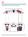
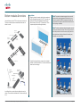
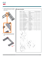
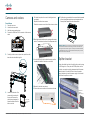
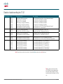
Related documents What has changed? Tools needed The following documents are also available: General: You will need the following tools and equipment when assembling the system: • • • • • • • T3 Room Recommendations Guide 119076 Maintenance Guide: 78-19801 Cable Schematics: 78-19798 Room Installation Guide: 78-19802 Quick User Reference Guide: 78-19804 Document Camera Assembly Guide: 78-19800 Ceiling Lights Assembly Guide: 78-19799 With the exception of the Room Recommendations Guide all of these documents are supplied with the Systems they describe. Should you nevertheless need any of these documents, contact your Cisco partner. • • • • • The removal of the splitter in the left system bottom module has caused changes in the cabling structure descriptions. This is reflected in revised cable structure drawings and corresponding tables. The presentation monitor assembly installation procedure has been changed in this version. Revised description of bottom module assembly procedure. Recommended sequence is to start with the innermost (the right) module—as viewed from the recommended door location. It used to be the left module. Ceiling light assembly is now moved to a separate document. Document camera installation is now a separate document Additions, changes and updates • • • • • • • • • • • • • • • 78-19803-02 Cisco TelePresence System T3 System Assembly Guide, December 2011 Illustrations showing the need for keeping the distance between the table and the rear wall at 130 cm. Fastening the left bottom module. Drawing describing splitter bracket mounting in right bottom module. Drawing showing revised floor cabling structure. Drawings showing monitors when mounting now shows monitors without grilles attached. Drawing showing revised system cabling structure. Drawing showing how the TCU is mounted in left table column. Drawing showing revised table cabling structure. Description of the presentation monitor assembly installation. Fire enclosure for document camera associated equipment. Drawing showing document camera location. Change in the document camera cabling. Description of document camera installation. Trip lists are now an integral part of the cover plates and need no mounting description. Drawing of the cover plates. • • • • • • • • • • • • • • • • • • • Spirit Level (bubble level) for light installation and monitor levelling. 13 mm open end/box wrench to fasten bottom module to steel structure, columns to steel structure, table to columns. 10 mm open end wrench to fasten floor structure center to left/right, adjusting table top tighteners, codec brackets to bottom module, adjusting TCU, Splitter, Switch and Power brackets, cleaning kit and doc pockets, fasten center cover plates. 1 ⁄4” ratchet wrench 1 ⁄4” socket extension 13 mm deep socket to fasten table column to steel structure and to fasten the table. 10 mm socket to fasten splitter to bottom module, adjust center door bottom module and fasten table to columns. 7 mm socket to dismount screws in bottom module and monitors (preparing for angle plate between screens). 5 mm Allen bit for height adjustment of monitor systems. 4 mm Allen bit to removing cable hatches in bottom module, fasten center cover plates. 3 mm Allen bit to mount angle plate between screens. 2.5 mm Allen bit to dismount screws in bottom module and monitors (preparing for angle plate between screens)and dismount/mount column covers. 2 mm Allen wrench for cable clamps in cable wells. Torx T10 to fasten codec brackets to codecs, fasten cleaning kit and doc pockets. Torx T20 to fasten power outlet brackets in cable wells. Portable drill Hammer for cable wells power outlets (if installation is to be done). Blade screwdriver for cable wells power outlets (if installation is to be done). 1 ⁄4” deep socket to fasten cable wells power outlets to the brackets (if installation is to be done). Page 3 of 28