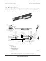
1
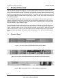
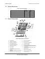
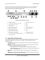
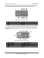
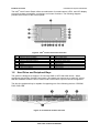
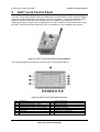
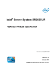
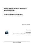
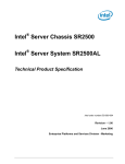
Intel® Server System SR1550AL
List of Figures
List of Figures
Figure 1. Front View (Shown with Standard Control Panel Bezel) ............................................... 1
Figure 2. Front View without Bezel (Shown with Standard Control Panel Option) ....................... 1
Figure 3. Back View (Shown with 1+1 Power Supply Configuration)............................................ 1
Figure 4. Major System Components ........................................................................................... 2
Figure 5. Back Panel Feature Overview ....................................................................................... 3
Figure 6. Control Panel Modules .................................................................................................. 4
Figure 7. Mini Control Panel Overview ......................................................................................... 5
Figure 8. Standard Control Panel Overview ................................................................................. 5
Figure 9. Intel® Local Contol Panel Overview ............................................................................... 6
Figure 10. Front Panel Feature Overview..................................................................................... 6
Figure 11. Optional Front Bezel .................................................................................................... 9
Figure 12. Front Bezel Supporting Mini Control Panel.................................................................. 9
Figure 13. Front Bezel Supporting Standard Control Panel.......................................................... 9
Figure 14. Front Bezel Supporting Intel® Local Control Panel .................................................... 10
Figure 15. PS Module Enclosure - Dimensional Drawing ........................................................... 11
Figure 16. Fan Module................................................................................................................ 18
Figure 17. Fan Header Assignments on Mid-Plane .................................................................... 18
Figure 18. Power Supply Air Duct............................................................................................... 18
Figure 19. CPU Air Duct ............................................................................................................. 18
Figure 20. 2.5” Drive Blank ......................................................................................................... 18
Figure 21. Passive Mid-Plane Board .......................................................................................... 18
Figure 22. Active SAS/SAS RAID Mid-Plane Board ................................................................... 18
Figure 23. Bridge Board.............................................................................................................. 18
Figure 24. Hot-Swap SAS/SATA Backplane (Front Side View) .................................................. 18
Figure 25. Hot-Swap SAS/SATA Backplane (Back Side View) .................................................. 18
Figure 26. Slimline Optical Drive Assembly ................................................................................ 18
Figure 27. Hard Drive Tray Assembly ......................................................................................... 18
Figure 28. Passive Mid-Plane Board .......................................................................................... 18
Figure 29. Active Mid-plane with SAS / SAS RAID Support ....................................................... 18
Figure 30. Active Mid-plane Architecture Diagram ..................................................................... 18
Figure 31. Hot-Swap SAS/SATA Backplane (Front Side View) .................................................. 18
Figure 32. Hot-Swap SAS/SATA Backplane (Back Side View) .................................................. 18
Figure 33. SAS/SATA Backplane Functional Block Diagram ..................................................... 18
Figure 34. Mini Control Panel Assembly Module ........................................................................ 18
Figure 35. Mini Control Panel LED’s........................................................................................... 18
Revision – 1.3
ix
Intel order number D31982-006