1
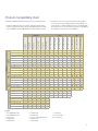
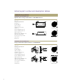
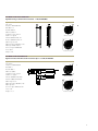
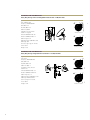
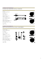
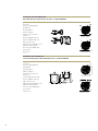
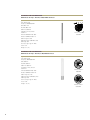
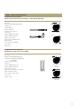
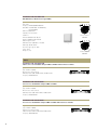
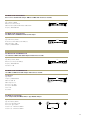
Motorola Enterprise
Wireless LAN Antennas
Using this guide
This guide has been designed to help you choose the right Motorola antenna
and accessories for your wireless LAN deployment. It explains key factors to
consider when choosing an antenna, and provides tables illustrating various key
characteristics of each antenna. A compatibility chart is also provided to show
which Motorola products are compatible with each other and what accessories
may be required to complete the system. A Motorola representative or sales
partner can also help you determine the best configuration for your installation.
Table of Contents
Using this guide.........................................................................................................2
Antenna Selection.....................................................................................................3
Key antenna specifications........................................................................................3
Antennas and related accessories for Motorola’s Enterprise WLANs....................4
Choosing the right antenna and accessories............................................................4
Product compatibility chart........................................................................................5
Antenna part number and description tables...........................................................6
2.4 GHz (802.11b/g/n) Antennas...............................................................................6
5 GHz (802.11a/n) Antennas...................................................................................12
Dual-band (802.11a/b/g/n) Antennas.......................................................................15
Cables......................................................................................................................16
Adapters...................................................................................................................17
Lightning Arrestors..................................................................................................18
Mounting Kits..........................................................................................................19
Antenna selection
While several antennas may work in a given
environment, some will provide better coverage
than others. Using the right antenna in the right
location will maximize both the performance and
coverage of your network. Understanding the key
characteristics that describe how an antenna sends
and receives radio frequency signals is critical to
finding the ideal antenna.
Motorola Enterprise Wireless LAN products operate
in the 2.4 GHz and 5 GHz ISM bands allocated for
unlicensed use. Access point and access port products
available today support either the 802.11b/g or the
802.11a standard, or both. Wireless devices conforming
to the 802.11b/g standard operate in the 2.4 GHz
ISM band, while 802.11a devices operate in the
5 GHz band. The antennas in this guide are grouped
according to the frequency band they support. Note
that some antennas are designed to operate on either
band. These antennas, described as “Dual-band”
may be connected to radios operating in either the
2.4 or 5 GHz bands, although a single antenna may
not be connected to two radios at the same time.
They usually have gain greater than 5 dBi and are
not suitable for omni-directional situations. Ideally
suited for long hallways.
Patch: A flat antenna that is mounted on the ceiling
but whose pattern is omni-directional. Most of the
energy goes out horizontally to the sides of the
antenna and equal in all directions.
Dipole: A tubular antenna that can be either a pipe
shape, a straight flexible rod or a paddle. This antenna
has an omni-directional pattern when placed in a
vertical position. It usually has 2 dBi of gain.
Dipole Array: Essentially a dipole, a dipole array
is two or more dipoles that are placed one on top
of the other, requiring a longer tube to hold them.
The advantage of a dipole array is that it has
higher gain.
Parabolic Grid: (PGA) A very directional, dish-like
antenna. Its parabolic reflector focuses the RF energy
like a flashlight. Most of the time the radiating
element is a dipole, but when combined with the
dish, it becomes very directional with gain up to 24
dBi. Usually used in long point-to-point systems.
In addition to frequency of operation, there are other
key specifications to consider when choosing an
antenna. These characteristics are included for each
Motorola antenna in the tables on page 6, and are
defined below for your reference:
Yagi: An antenna that has an internal structure
resembling that of typical antennas used for TV
reception (a series of rods perpendicular to a main
rod, making a triangular shape). This is a directional
antenna with less gain than the PGA, typically
around 13 dBi. It may be used in either point-to-point
situations, or to cover a very long, narrow area in
point-to-multi-point situations.
Pattern
Additional terms
Key antenna specifications
Omni-Directional: Signal radiates from the antenna
in all directions on the horizontal plane.
Directional: Signal radiates in a specific direction,
typically described as a beam of given width,
expressed in degrees in the horizontal and
vertical plane. (See Azimuth and Elevation
Beamwidth below)
Type
Panel: A flat antenna that is mounted to a wall
or other vertical surface and radiates RF energy
(radio waves) directionally away from the wall.
Frequency: the frequency band within which the
antenna performs at the stated specifications.
Gain (dBi): The relative amplification of the antenna
with respect to an equivalent isotropic antenna,
expressed on the decibel logarithmic scale.
Cable loss (dB): The signal strength loss introduced
by the cable connected to the antenna expressed on
the decibel logarithmic scale.
Net gain (dBi): The resulting amplification of the
antenna paired with its cable.
Polarization: the orientation of the electrical field
which the antenna is optimized to receive. If the
transmitting and receiving antennas are both linear
polarized, then turning one 90° so that they are
cross polarized will reduce the range significantly.
VSWR: Voltage Standing Wave Ratio. The ratio of
maximum voltage to minimum voltage along the
line. Expresses the degree of match between the
transmission line and the terminating element
(antenna). When VSWR is 1:1 the match is perfect, a
VSWR of 1.5:1 corresponds to 96% power efficiency.
Azimuth 3dB Beamwidth: width of the antenna
beam on the horizontal plane expressed in degrees.
Elevation 3dB Beamwidth: height of the antenna
beam on the vertical plane expressed in degrees.
Antennas and related
accessories for Motorola’s
Enterprise WLANs
Motorola offers a complete selection of antennas
and accessories to ensure optimal coverage
and performance for 802.11a/b/g wireless
LANs. Regardless of the size or layout of your
environment, from a small office or storefront to
campus-wide, multiple-site, indoor and outdoor
deployments, Motorola offers the antennas, cables
and accessories designed to fit your needs.
By combining this portfolio with a broad line of
wireless switches, access ports, access points,
client connectivity cards, ruggedized mobile voice/
data devices and network management software, as
well as wireless mobility planning and deployment
services, Motorola offers comprehensive end-to-end
wireless enterprise LAN solutions, giving you secure,
reliable access to your critical business data and
applications at the point of activity. For more
information on Motorola’s wireless products,
visit www.symbol.com/wireless
Choosing the right antenna and accessories
for your Motorola enterprise WLAN
It is important to consider a number of factors
when choosing an antenna and accessories for your
Motorola enterprise WLAN. In order to choose the
right components, you’ll need to know:
•
Where you will be installing the antenna, and
what type of coverage you will require
•
In which band (i.e. 802.11b/g or 802.11a) your
network operates
•
Which Motorola AP you plan to use
•
Whether you will be deploying the network
indoors or outdoors
•
The distance between AP and antenna, to
determine extender cable length, if any
With this information, review the tables below and
determine which antennas might suit your needs.
Using the part numbers provided in the tables, go
to the compatibility chart on page 5 to determine
which of the possible antennas will work with your
hardware in your environment. If you’d prefer, you
may go to the compatibility chart first, and then look
up the antennas listed in the table below to find the
one that best meets your needs.
Product compatibility chart
To find the right antenna and accessories for your deployment:
2. Follow the row of the chosen antenna across the table
to the columns for the lightning arrestors and cables you
wrote down to confirm that they are also compatible with
the antenna you’ve chosen and to determine if an adaptor
is required to connect two selected parts.
1. Find your AP at the top of the chart, and follow that column
down to find the antennas, cables and lightning arrestors that
are compatible with that AP. Write those part numbers down.
Cables
AP-5181 A
AP-5181 B/G
ML-1499-72PJ-01R
ML-1499-LAK1-01R
ML-1499-LAK2-01R
ML-2452-LAK1-01R
X
3
X
X
1
1
1
1
•
2
2
2
8
X
7
X
X
A
A
A
A
X
•
•
•
ML-2499-7PNA2-01R
X
•
X
3
X
X
1
1
1
1
•
2
2
2
ML-2499-APA2-01
X
•
X
•
X
X
X
X
X
X
X
X
X
X
ML-2499-BPNA3-01R
X
9
X
6
X
X
•
•
•
•
X
X
•
X
ML-2499-BYGA2-01R
X
9
X
6
X
X
•
•
•
•
X
X
•
X
ML-2499-FHPA5-01R
X
X
X
X
X
•
A
A
A
A
X
u
u
u
ML-2499-FHPA9-01R
X
X
X
X
X
•
A
A
A
A
X
u
u
u
ML-2499-HPA3-01R
X
•
X
•
X
X
1
1
1
1
•
2
2
2
ML-2499-PNAHD-01R
X
•
X
3
X
X
1
1
1
1
•
2
2
2
ML-2499-SD3-01R
X
•
•
3
X
X
1
1
1
1
•
2
2
2
ML-1499-50JK-01R
AP-5131 B/G
•
X
ML-1499-25JK-01R
AP-5131 A
X
ML-2499-5PNL-72-N
ML-1499-10JK-01R
AP300 B/G
ML-2499-11PNA2-01R
AP300 A
2.4 GHz
Antennas
LAs
•
X
•
X
X
X
X
X
X
X
X
X
X
X
X
X
X
X
•
X
A
A
A
A
X
u
u
u
ML-5299-FHPA6-01R
X
X
X
X
•
X
A
A
A
A
X
u
u
u
ML-5299-HPA1-01R
•
X
•
X
X
X
4
4
4
4
X
5
5
5
ML-5299-PTA1-01R
•
X
•
X
X
X
4
4
4
4
X
5
5
5
ML-5299-WPNA1-01R
•
X
•
X
X
X
4
4
4
4
X
5
5
5
ML-2452-APA2-01
•
X
•
•
X
X
X
X
X
X
X
X
X
X
X
X
X
X
•
•
A
A
A
A
X
u
u
u
ML-2452-PNA7-01R
X
X
X
X
•
•
A
A
A
A
X
u
u
u
ML-2452-PNA5-01R
ML-1499-LAK1-01R
X
•
X
X
u
u
•
•
•
•
•
ML-1499-LAK2-01R
X
X
X
X
u
u
•
•
•
•
X
ML-2452-LAK1-01R
•
X
•
•
u
u
•
•
•
•
X
ML-1499-100JK-01R
7
X
7
7
•
•
ML-1499-10JK-01R
7
X
7
7
•
•
ML-1499-25JK-01R
7
X
7
7
•
•
ML-1499-50JK-01R
7
X
7
7
•
•
ML-1499-72PJ-01R
X
•
X
X
X
X
Cables
Dual
ML-5299-APA1-01R
ML-5299-FHPA10-01R
LAs
5 GHz
ML-1499-100JK-01R
AP Radios
Legend
1 - ML-1499-RBNCA1-01R
6 - 25-85391-01R
• - Compatible
2 - ML-1499-RBNCA2-01R
7 - 25-85392-01R
X - Not Compatible
3 - 25-72178-01
8 - Must use ML-1499-LAK1-01R
u - Not Required
4 - 25-90262-01R
9 - 25-97261-01R
5 - 25-90263-01R
A - 25-99175-01R
Antenna part number and description tables
2.4 GHz (802.11b/g/n) Antennas
Part Number: ML-2499-5PNL-72-N
High Performance 135 Degree Panel Antenna - 5.5 dBi; N Male Connector
Specifications:
Type: Panel
Ft (MHz) 2437.0
Polarity V e r t
90
9/13/2005 12:20:01 PM
10.0
Frequency: 2400-2500 MHz
5.0
0.0
-5.0
-10.0
Gain (dBi): 7.5
-15.0
-20.0
-25.0
180
Net Gain (dBi): 5.5
-30.0
dBi
Cable Loss (dB): 2
B e a m w i d t h (°)
Polarization: Linear, Vertical
270
Beamwidth Ave (dBi)
134.1
5 .7 1
Azimuth Pattern
VSWR: 1.7:1
Azimuth 3dB Beamwidth: 135°
Ft (MHz) 2437.0
Polarity H o r z
90
9/13/2005 12:07:22 PM
Elevation 3dB Beamwidth: 56°
10.0
5.0
0.0
-5.0
Cable Length (in.): 72
-10.0
-15.0
-20.0
-25.0
Cable Attenuation (dB/100 ft.): 33.5
180
-30.0
dBi
Cable Type: RG-58 Ultralink
Connector Type: Type N – Male
270
B e a m w i d t h (°)
72.6
Beamwidth Ave (dBi)
6.32
Elevation Pattern
Power: 25 W
Weight: .5 lb
Part Number: ML-2499-7PNA2-01R
65 Degree H-Plane Diversity Directional Panel - 7 dBi, RP-BNC Male
Specifications:
Type: Panel
Model M L - 2 4 9 9 - 7 P N A 2 - 0 1 A z C u t
Ft (MHz) 2 4 5 0 . 0
90
Polarity V er t
10.0
5.0
Frequency: 2400-2500 MHz
0.0
-5.0
-10.0
Net Gain (dBi): 6.3
-15.0
6-21/32”
Gain (dBi): 7.6
-20.0
-25.0
180
-30.0
dBi
Cable Loss (dB): 1.3
Polarization: Linear, Vertical
270
0.84”
Beam width(°) 59.7
11/12/2003 2:50:29 PM
VSWR: 1.7:1 Typical
Azimuth Pattern
Azimuth 3dB Beamwidth: 60°
Elevation 3dB Beamwidth: 60°
Model M L - 2 4 9 9 - 7 P N A 2 - 0 1 E l C u t
Ft (MHz) 2 4 5 0 . 0
90
10.0
5.0
0.0
Cable Length (in.): 48
-5.0
-10.0
4-25/32”
Cable Attenuation (dB/100 ft.): 33.5
Polarity V er t
-15.0
-20.0
-25.0
180
-30.0
dBi
Cable Type: RG-58 Ultralink
Connector Type: RP-BNC Male
Power: 10 W
Weight: 9.6 oz
270
Beam width(°) 57.1
11/12/2003 2:53:26 PM
Elevation Pattern
Part Number: ML-2499-11PNA2-01R
High-Gain 97 Degree H-Plane Directional Panel - 11 dBi, RP-BNC Male
Specifications:
Type: Panel
Frequency: 2400-2500 MHz
Model
ML-2499-11PNA2-01R Az Cut
Ft (MHz) 2 4 5 0 . 0
90
Polarity V er t
10.0
5.0
2-3/32”
3-5/32”
0.0
-5.0
-10.0
Gain (dBi): 11.2
-15.0
-20.0
-25.0
180
Net Gain (dBi): 8.5
-30.0
dBi
Cable Loss (dB): 2.7
Polarization: Linear, Vertical
VSWR: 1.7:1 Typical
270
Beam width(°) 98.6
11/12/2003 7:47:48 PM
Azimuth Pattern
23-5/32”
Azimuth 3dB Beamwidth: 97°
Elevation 3dB Beamwidth: 14°
Mo del
ML-2499-11PNA2-01R El Cut
Ft (MHz) 2 4 5 0 . 0
90
Polarity V er t
10.0
5.0
0.0
Cable Length (in.): 96
Cable Attenuation (dB/100 ft.): 33.5
-5.0
-10.0
-15.0
-20.0
-25.0
180
-30.0
dBi
Cable Type: RG-58 Ultralink
Connector Type: RP-BNC-Male
Power: 50 W
270
Beam width(°) 13.7
11/12/2003 7:55:04 PM
Elevation Pattern
Weight: 1.5 lb
Part Number: ML-2499-APA2-01R
High Performance Omni-Directional ‘Fixed Point’ Dipole - 3.5 dBi, RP-BNC Male
Specifications:
Type: Dipole
Model ML-2499-APA2-01 Az Cu t
Ft (MHz) 2450.0
90
Polarity Vert
5.0
Frequency: 2400-2500 MHz
0.0
-5.0
-10.0
-15.0
Gain (dBi): 2
-20.0
-25.0
-30.0
Net Gain (dBi): 2
180
-35.0
dBi
Cable Loss (dB): 0
Polarization: Linear, Vertical
270
Beam width(°) 282.6
11/12/2003 4:13:41 P M
VSWR: 1.7:1 Typical
Azimuth Pattern
Azimuth 3dB Beamwidth: 360°
Elevation 3dB Beamwidth: 60°
Model ML-2499-APA2-01 El Cu t
Ft (MHz) 2450.0
90
Polarity Vert
5.0
0.0
Cable Length (in.): 0
-5.0
-10.0
-15.0
Cable Attenuation (dB/100 ft.): N/A
Cable Type: N/A
-20.0
-25.0
-30.0
180
-35.0
dBi
Connector Type: RP-BNC Female
Power: 2 W
Weight: 1.2 oz
270
Beam width(°) 16.6
11/12/2003 4:08:24 P M
Elevation Pattern
Part Number: ML-2499-BPDA1-01R
Heavy-Duty 10 Degree Directional High-Gain Parabolic Dish - 24 dBi, N Female
Specifications:
Type: Parabolic Dish
Model M L - 2 4 9 9 - B P D A - 0 1 A z c u t
Ft (MHz) 2 4 5 0 . 0
90
Polarity V er t
25.0
20.0
Frequency: 2400-2500 MHz
15.0
10.0
5.0
0.0
Gain (dBi): 23.5
-5.0
-10.0
-15.0
-20.0
20.85”
Net Gain (dBi): 23.5
180
-25.0
dBi
6.25”
Cable Loss (dB): 0
Polarization: Linear, Vertical
270
Beam width(°) 10.0
11/13/2003 1:21:15 PM
Azimuth Pattern
VSWR: 1.7:1 Typical
Azimuth 3dB Beamwidth: 10°
Model M L - 2 4 9 9 - B P D A - 0 1 A z c u t
Ft (MHz) 2 4 5 0 . 0
90
Elevation 3dB Beamwidth: 11°
Polarity V er t
25.0
20.0
15.0
10.0
5.0
Cable Length (in.): 0
0.0
-5.0
-10.0
-15.0
Cable Attenuation (dB/100 ft.): N/A
-20.0
180
-25.0
dBi
Cable Type: N/A
Connector Type: Type N – Female
270
Beam width(°) 10.0
11/13/2003 1:21:15 PM
Power: 50 W
Elevation Pattern
Weight: 13 lb
Part Number: ML-2499-BPNA3-01R
Heavy-Duty 35 Degree High-Gain Directional Panel - 14.5 dBi, N Female
Specifications:
Type: Panel
Model M L - 2 4 9 9 - B P N A 3 - 0 1 A z C u t
Ft (MHz) 2 4 5 0 . 0
Polarity V er t
90
15.0
Frequency: 2400-2500 MHz
10.0
5.0
0.0
-5.0
Gain (dBi): 13.9
-10.0
-15.0
-20.0
-25.0
Net Gain (dBi): 13.6
180
-30.0
dBi
Cable Loss (dB): .3
Polarization: Linear, Vertical
10.13 ± .04”
270
Azimuth Pattern
1.58 ± .04”
Azimuth 3dB Beamwidth: 31°
5.14”
Elevation 3dB Beamwidth: 28°
Cable Length (in.): 12
Beam width(°) 31.3
11/12/2003 4:49:00 PM
VSWR: 1.5:1
Model ML-2499-BPNA3-01 El Cut
Ft (MHz) 2 4 5 0 . 0
90
10.13 ± .04”
Polarity V er t
15.0
10.0
5.0
0.0
-5.0
-10.0
Cable Attenuation (dB/100 ft.): 33.5
-15.0
-20.0
-25.0
Cable Type: RG-58 Ultralink
180
-30.0
dBi
Connector Type: N – Female
Power: 50 W
270
Beam width(°) 28.1
11/12/2003 4:44:40 PM
Weight: 1.5 lb
Elevation Pattern
Part Number: ML-2499-BYGA2-01R
Heavy-Duty 35 Degree High-Gain Directional Yagi - 15 dBi, N Female
Specifications:
Type: Yagi
Model M L - 2 4 9 9 - B Y G A 2 - 0 1 A z C u t
Ft (MHz) 2 4 5 0 . 0
Polarity V er t
90
15.0
Frequency: 2400-2500 MHz
10.0
5.0
0.0
-5.0
Gain (dBi): 14.1
-10.0
-15.0
-20.0
-25.0
Net Gain (dBi): 13.9
180
-30.0
dBi
Cable Loss (dB): .3
1.40”
Polarization: Linear, Vertical
Beam width(°) 27.8
270
11/12/2003 5:58:10 PM
VSWR: 1.5:1 Typical
Azimuth Pattern
26.44”
Azimuth 3dB Beamwidth: 28°
Elevation 3dB Beamwidth: 27°
3.73”
Mo del M L - 2 4 9 9 - B Y G A 2 - 0 1 E l C u t
Ft (MHz) 2 4 5 0 . 0
Polarity V e r t
90
15.0
10.0
Cable Length (in.): 12
5.0
0.0
-5.0
-10.0
Cable Attenuation (dB/100 ft.): 33.5
-15.0
-20.0
-25.0
180
Cable Type: RG-58 Ultralink
-30.0
dBi
Connector Type: Type N – Female
Power: 50 W
Beam width(°) 27.2
270
11/12/2003 6:00:02 PM
Weight: 1.25 lb
Elevation Pattern
Part Number: ML-2499-HPA3-01R
High Performance Omni-Directional “Pipe” Antenna - 5 dBi, RP-BNC Male
Specifications:
Type: Dipole Array
Model M L - 2 4 9 9 - H P A 3 - 0 1 A z C u t
Ft (MHz) 2 4 5 0 . 0
Polarity V er t
90
5..0
5
0
Frequency: 2400-2500 MHz
0.0
-5.0
-10.0
Gain (dBi): 4.6
-15.0
-20.0
-25.0
Net Gain (dBi): 3.3
-30.0
-35.0
180
dBi
Cable Loss (dB): 1.3
Polarization: Linear, Vertical
VSWR: 1.7:1
Azimuth 3dB Beamwidth: 360°
270
11-9/16”
Beam width (°) 360
11/12/2003 6:22:13 PM
Azimuth Pattern
S2 4 0 3B P X
2. 4- 2. 5 GH z, 3d B d Omnidirectional
Elevation 3dB Beamwidth: 31°
Model M L - 2 4 9 9 - H P A 3 - 0 1 E l C u t
PLASTIC
SPACER
Cable Length (in.): 48
Cable Attenuation (dB/100 ft.): 33.5
Cable Type: RG-58 Ultralink
Ft (MHz) 2 4 5 0 . 0
Polarity V e r t
90
0
5..0
5
0.0
-5.0
-10.0
1-1/8”
-15.0
-20.0
-25.0
-30.0
180
-35.0
dBi
Connector Type: RP-BNC Male
Power: 50 W
Weight: .03 lb
270
Beam width(°) 14.3
11/12/2003 6:19:10 PM
Elevation Pattern
Part Number: ML-2499-PNAHD-01R
Heavy-Duty 65 Degree H-Plane Directional Panel - 6.3 dBi, RP-BNC Male
Specifications:
Type: Panel
Model M L - 2 4 9 9 - P N A H D - 0 1 A z C u t
Ft (MHz) 2 4 5 0 . 0
Polarity V er t
90
10.0
5.0
Frequency: 2400-2500 MHz
0.0
-5.0
-10.0
Gain (dBi): 7.6
-15.0
-20.0
-25.0
-30.0
Net Gain (dBi): 6.3
180
-35.0
dBi
Cable Loss (dB): 1.3
Polarization: Linear, Vertical
270
Beam width(°) 55.3
11/12/2003 6:41:17 PM
VSWR: 1.7:1
Azimuth Pattern
3.810”
1.160”
Azimuth 3dB Beamwidth: 55°
Elevation 3dB Beamwidth: 56°
4.558”
Model M L - 2 4 9 9 - P N A H D - 0 1 E l C u t
Ft (MHz) 2 4 5 0 . 0
Polarity V er t
90
10.0
5.0
Cable Length (in.): 48
0.0
-5.0
-10.0
-15.0
Cable Attenuation (dB/100 ft.): 33.5
-20.0
-25.0
-30.0
180
Cable Type: RG-58 Ultralink
-35.0
dBi
Connector Type: RP-BNC Male
Power: 50 W
270
Beam width(°) 56.2
11/12/2003 6:44:37 PM
Weight: .5 lb
Elevation Pattern
Part Number: ML-2499-SD3-01R
Low Profile Ceiling/Surface Mount Omni-Directional - 3.5 dBi, RP-BNC Male
Specifications:
Type: Panel
Model M L - 2 4 9 9 - S D 3 - 0 1 A z C u t
Ft (MHz) 2 4 5 0 . 0
Polarity V e r t
90
5..0
5
0
Frequency: 2400-2500 MHz
0.0
-5.0
-10.0
Gain (dBi): 4.8
-15.0
-20.0
-25.0
-30.0
Net Gain (dBi): 3.5
180
-35.0
dBi
Cable Loss (dB): 1.3
2.35±0.06”
Polarization: Linear, Vertical
270
VSWR: 1.7:1
Azimuth 3dB Beamwidth: 360°
Azimuth Pattern
4-3/32”
Elevation 3dB Beamwidth: 52°
Mo del ML-2499-SD3-01 El Cut
Ft (MHz) 2 4 5 0 . 0
Polarity V er t
90
Cable Length (in.): 48
5.0
0.0
-5.0
4-3/32”
7/8”
-10.0
Cable Attenuation (dB/100 ft.): 33.5
Cable Type: RG-58 Ultralink
360
B e a m w i d t h( ° )
11/24/2003 4:14:27 PM
2.05±0.06”
-15.0
-20.0
-25.0
-30.0
180
-35.0
dBi
Connector Type: RP-BNC Male
Power: 10 W
270
Weight: 3.2 oz
10
Beam width(°) 51.7
11/12/2003 6:54:30 PM
Elevation Pattern
Part Number: ML-2499-FHPA5-01R
Omni-Directional “Pipe” Antenna - 7.7 dBi, N Male Connector
Specifications:
Type: Dipole Array
Mount Wall
Main/Aux Single
Cut Az
Polarity Vert
90
Frequency: 2400-2500 MHz
10.0
5.0
Hz 2.450G
0.0
-5.0
-10.0
Gain (dBi): 7.7
-15.0
-20.0
-25.0
Net Gain (dBi): 7.7
-30.0
180
dBi
Cable Loss (dB): 0.0
Polarization: Linear, Vertical
270
VSWR: 2:1
Beam width(°) 45.9
Azimuth Pattern
2450 MHz
Azimuth 3dB Beamwidth: 360°
Elevation 3dB Beamwidth: 25°
Cable Length (in.): N/A
Cable Attenuation (dB/100 ft.): N/A
Cable Type: N/A
Connector Type: Type N – Male
Power: 10 W
Weight: .7 (.3)
Part Number: ML-2499-FHPA9-01R
Omni-Directional “Pipe” Antenna - 9 dBi, N Male Connector
Specifications:
Type: Dipole Array
Frequency: 2400-2500 MHz
Mount Wall
Main/Aux Single
Cut Az
Polarity Vert
90
10.0
5.0
Hz 2.450G
0.0
-5.0
Gain (dBi): 9.0
-10.0
-15.0
-20.0
Net Gain (dBi): 9.0
-25.0
180
-30.0
dBi
Cable Loss (dB): 0
Polarization: Linear, Vertical
VSWR: 2:1
Azimuth 3dB Beamwidth: 360°
Elevation 3dB Beamwidth: 14°
270
Beam width(°) 45.9
Azimuth Pattern
2450 MHz
Cable Length (in.): N/A
Cable Attenuation (dB/100 ft.): N/A
Cable Type: N/A
Connector Type: Type N – Male
Power: 10 W
Weight: 1.1 (.5)
11
5.2 GHz (802.11a) Antennas
Part Number: ML-5299-APA1-01R
High Performance Fixed Point Dipole - 2 dBi, RP-SMA Female Connector
Specifications:
Type: Dipole
ML-5299-APA1-01 Az Cut
Model
Ft (MHz) 5250.0
Polarity V e r t
90
5.0
0.0
Frequency: 4900-5875 MHz
-5.0
-10.0
-15.0
Gain (dBi): 2.0/2.0
-20.0
-25.0
-30.0
180
Net Gain (dBi): 2.0/2.0
Cable Loss (dB): N/A
-35.0
dBi
5.4” MAX.
0.60”
Polarization: Linear, Vertical
270
Beam width(°) 3 0 2 . 4
1/7/2004 8:42:26 PM
Azimuth Pattern
VSWR: 1.5:1
Azimuth 3dB Beamwidth: 360°
3.58”
ML-5299-APA1-01 El Cut
Model
Elevation 3dB Beamwidth: 75°
Ft (MHz) 5250.0
Polarity V e r t
90
5.0
0.0
-5.0
-10.0
Cable Length (in.): N/A
-15.0
-20.0
-25.0
-30.0
Cable Attenuation (dB/100 ft.): N/A
180
-35.0
dBi
Cable Type: N/A
Connector Type: RP-SMA Male
270
Beam width(°)
75
1/7/2004 8:47:57 PM
Power: 1 W
Elevation Pattern
Weight: 1 oz
Part Number: ML-5299-HPA1-01R
High Performance Omni-Directional Antenna - 5 dBi, RP-SMA Female Connector
Specifications:
Type: Dipole Array
ML-5299-HPA1-01 Az Cut
Model
Ft (MHz) 5250.0
90
Polarity V e r t
5.0
0.0
Frequency: 4900-5875 MHz
-5.0
-10.0
-15.0
Gain (dBi): 5.9
-20.0
-25.0
-30.0
180
-35.0
Net Gain (dBi): 5
dBi
Cable Loss (dB): .84
Polarization: Linear, Vertical
VSWR: 2:1
270
Beam width(°) 90.6
12/15/2003 11:48:02 AM
11-9/16”
Azimuth Pattern
Azimuth 3dB Beamwidth: 360°
Elevation 3dB Beamwidth: 17°
Model
ML-5299-HPA1-01 El Cut
Ft (MHz) 5250.0
90
Po l ar i ty V e r t
5.0
0.0
Cable Length (in.): 36
Cable Attenuation (dB/100 ft.): 28
-5.0
-10.0
-15.0
-20.0
1-1/8”
-25.0
-30.0
-35.0
180
dBi
Cable Type: LMR195
Connector Type: RP-SMA Male
Power: 5 W
Weight: 0.3 lb
12
270
Beam width(°) 17.0
12/15/2003 11:40:30 AM
Elevation Pattern
Part Number: ML-5299-PTA1-01R
Low Profile Ceiling-Tile Mount Panel - 2 dBi, RP-SMA Female Connector
Specifications:
Type: Patch
5/8”
Model
Version
802.11a Squint
Horz. Mount Az Scan
2-5/32”
Ft (MHz) 5775.0
Polarity V e r t
90
5..0
5
0
Frequency: 4900-5875 MHz
0.0
-5.0
-10.0
-15.0
Gain (dBi): 6.5/2.0
-20.0
-25.0
-30.0
Net Gain (dBi): 4.5/0
180
-35.0
dBi
2-5/32”
Cable Loss (dB): 2
Polarization: Linear, Vertical
Peak
mean
%
1 .4 3
0 .0 3
100
0.175
Azimuth Pattern
Azimuth 3dB Beamwidth: 360°
Elevation 3dB Beamwidth: 45°5/8”
Beam width(°) 3 1 8 . 5
270
7/14/2004 10:46:06 AM
VSWR: 1.5:1
2-5/32”
Model
Version
802.11a Squint
Horz. Mount El Scan
Ft (MHz) 5745.0
Polarity V e r t
90
5 .0
5.
0
0.0
Cable Length (in.): 36
-5.0
-10.0
-15.0
Cable Attenuation (dB/100 ft.): 2.15
Cable Type: RG-58
-20.0
-25.0
-30.0
180
2-5/32”
-35.0
dBi
Connector Type: RP-SMA Male
Power: 2 W
Beam width(°) 44.6
270
7/14/2004 11:27:25 AM
Weight: 2.4 lb
Peak
mean
%
4 .6 1
-1.04
73
0.547
Elevation Pattern
Part Number: ML-5299-WPNA1-01R
Wall Mount Panel Antenna w/Articulating Mount - 13 dBi, RP-SMA Female
Specifications:
Type: Panel
ML-5299-WPNA1-01 Az Cut
Model
Ft (MHz) 5250.0
Polarity V e r t
90
20.0
Frequency: 4900-5875 MHz
15.0
Gain (dBi): 14.2
-5.0
10.0
5.0
0.0
-10.0
-15.0
4-3/32”
-20.0
-25.0
Net Gain (dBi): 13
Cable Loss (dB): 1.2
-30.0
180
dBi
1-3/8”
Polarization: Linear, Vertical
270
Beam width(°) 27.9
1/5/2004 3:09:33 PM
VSWR: 2:1
Azimuth Pattern
Azimuth 3dB Beamwidth: 31°
Elevation 3dB Beamwidth: 27°
4-3/32”
Model
ML-5299-W PNA1-01 El Cut
Ft (MHz) 5250.0
90
Polarity V e r t
20.0
15.0
Cable Length (in.): 36
10.0
5.0
0.0
-5.0
Cable Attenuation (dB/100 ft.): 40
-10.0
-15.0
-20.0
-25.0
Cable Type: RG-303
180
-30.0
dBi
Connector Type: RP-SMA Male
Power: 10 W
Weight: 0.7 lb
270
Beam width(°) 23.3
1/5/2004 3:16:21 PM
Elevation Pattern
13
Part Number: ML-5299-FHPA10-01R
Omni-Directional “Pipe” Antenna, 10 dBi, N-Male Connector
Specifications:
Type: Dipole Array
Frequency: 4900-5850 MHz
Mount Wall
Main/Aux Single
Cut Az
Polarity Vert
90
10.0
5.0
Hz 5.570G
0.0
-5.0
-10.0
Gain (dBi): 10.0
-15.0
-20.0
-25.0
Net Gain (dBi): 10.0
180
-30.0
dBi
Cable Loss (dB): 0.0
Polarization: Linear, Vertical
VSWR: 2:1
Azimuth 3dB Beamwidth: 360°
270
Beam width(°) 148.4
Azimuth Pattern
5570 MHz
Elevation 3dB Beamwidth: 13°
Cable Length (in.): N/A
Cable Attenuation (dB/100 ft.): N/A
Cable Type: N/A
Connector Type: Type N – Male
Power: 5 W
Weight: .37 (.17)
Part Number: ML-5299-FHPA6-01R
Omni-Directional “Pipe” Antenna, 8 dBi, N-Male Connector
Specifications:
Type: Dipole Array
Frequency: 4900-5850 MHz
Gain (dBi): 8.0
Net Gain (dBi): 8.0
Cable Loss (dB): 0.0
Polarization: Linear, Vertical
VSWR: 2:1
Azimuth 3dB Beamwidth: 360°
Elevation 3dB Beamwidth: 16°
Azimuth Pattern
5500 MHz
Cable Length (in.): N/A
Cable Attenuation (dB/100 ft.): N/A
Cable Type: N/A
Connector Type: Type N – Male
Power: 5 W
Weight: .37 (.17)
Elevation Pattern
5500 MHz
14
2.4GHz - 5.2GHz Dual Band Antennas
Part Number: ML-2452-APA2-01
High Performance Dual Band Fixed Point Dipole - 3 dBi/4 dBi, RP-SMA Female
Specifications:
Type: Dipole
Model
Version
ML-2452-APA2-01
Vert Mount, Az Cut
Ft (MHz) 2436.0
Polarity V e r t
90
2/18/2005 12:50:46 PM
10.0
5.0
Frequency: 2400-2500/5150-5850 MHz
0.0
-5.0
-10.0
Gain (dBi): 3,4
Net Gain (dBi): 3,4
-15.0
-20.0
-25.0
180
-30.0
dBi
Cable Loss (dB): N/A
Polarization: Linear, Vertical
Azimuth Pattern
VSWR: 1.92:1
Azimuth 3dB Beamwidth: 360°
Elevation 3dB Beamwidth: 35°
Beam width(°) 91.8
270
Model
Version
ML-2452-APA2-01
V ert Mo unt , E l C ut
3/7/2005 10:59:30 AM
Ft (MHz) 2437.0
90
Polarity H o r z
10.0
5.0
0.0
-5.0
Cable Length (in.): N/A
-10.0
-15.0
-20.0
Cable Attenuation (dB/100 ft.): N/A
-25.0
180
-30.0
dBi
Cable Type: N/A
Connector Type: RP-SMA Male
Power: 10 W
270
Beam width(°) 45.6
Elevation Pattern
Weight: 0.7 oz
Part Number: ML-2452-PNA5-01R
Dual Band Panel, 5 dBi, Connector Type N-Male
Specifications:
Type: Panel
Frequency: 2400-2500/4900-5900 MHz
Mount Wall
Main/Aux Single
Cut Az
Polarity Vert
90
10.0
5.0
Hz 2.450G
0.0
-5.0
-10.0
Gain (dBi): 4.5 (2400-2500); 5.0 (4900-5250);
7.5 (5250-5900)
-15.0
-20.0
-25.0
180
-30.0
dBi
Polarization: Linear, Vertical
VSWR: 2:1
270
Beam width(°) 106.1
Azimuth Pattern
2450 MHz
Azimuth 3dB Beamwidth: 120°
Elevation 3dB Beamwidth: 65°
Cable Length (in.): 30.5
Mount Wall
Cable Attenuation (dB/100 ft.): 1.01/1.96
Main/Aux Single
Cut Az
90
10.0
0.0
-5.0
Cable Type: RG-58 Ultralink
Connector Type: Type N – Male
Polarity Vert
5.0
Hz 5.500G
-10.0
-15.0
-20.0
-25.0
180
-30.0
dBi
Power: 5 W
Weight: .2 (.09)
270
Beam width(°) 113.3
Elevation Pattern
2450 MHz
15
Part Number: ML-2452-PNA7-01R
Dual Band Panel, 7 dBi, Connector Type N-Male
Specifications:
Type: Panel
Frequency: 2400-2500/4900-5900 MHz
Mount Wall
Main/Aux Single
Cut Az
Polarity Vert
90
10.0
5.0
Hz 2.450G
0.0
-5.0
-10.0
Gain (dBi): 7.8 (2400-2500); 7.0 (4900-5250);
10.7 (5250-5900)
-15.0
-20.0
-25.0
180
-30.0
dBi
Cable Loss (dB): 0.3/0.7
Polarization: Linear, Vertical
270
VSWR: 2:1
Beam width(°) 51.4
Azimuth Pattern
2450 MHz
Azimuth 3dB Beamwidth: 68°/ 52°
Elevation 3dB Beamwidth: 66°/ 60°
Cable Length (in.): 30.5
Mount Wall
Main/Aux Single
Cut Az
Polarity Vert
90
10.0
5.0
Hz 5.500G
0.0
Cable Attenuation (dB/100 ft.): 1.01/1.96
Cable Type: RG-58 Ultralink
-5.0
-10.0
-15.0
-20.0
-25.0
180
-30.0
dBi
Connector Type: Type N – Male
Power: 10 W
Weight: .5 (.23)
270
Beam width(°) 56.6
Elevation Pattern
5500 MHz
Cables
Part Number: ML-1499-100JK-01R
100 ft. Low-Loss Coaxial Cable Jumper: N Male to N Male with 2 Connector Seal Kits
Specifications:
Type: Ultralink TL 93605
1200 ±2.0”
RF Connectors: N (m) to N (m)
Cable Attenuation (dB): 10.6 @ 2.4 GHz; 15.5 @ 5.8 GHz
Frequency: 2400-2500 MHz
Part Number: ML-1499-10JK-01R
10 ft. Low-Loss Coaxial Cable Jumper: N Male to N Male
Specifications:
Type: Ultralink TL 93605
120 ± 2.0”
RF Connectors: N (m) to N (m)
Cable Attenuation (dB): 2.0 @ 2.4 GHz; 2.9 @ 5.8 GHz
Frequency: 2400-2500 MHz
Part Number: ML-1499-25JK-01R
25 ft. Low-Loss Coaxial Cable Jumper: N Male to N Male with 2 Connector Seal Kits
Specifications:
Type: Ultralink TL 93605
RF Connectors: N (m) to N (m)
Cable Attenuation (dB): 2.5 @ 2.4 GHz; 4.0 @ 5.8 GHz
Frequency: 2400-2500 MHz
16
300 ± 2.0”
Part Number: ML-1499-50JK-01R
50 ft. Low-Loss Coaxial Cable Jumper: N Male to N Male with 2 Connector Seal Kits
Specifications:
Type: Ultralink TL 93605
600 ± 2.0”
RF Connectors: N (m) to N (m)
Cable Attenuation (dB): 4.5 @ 2.4 GHz; 7.0 @ 5.8 GHz
Frequency: 2400-2500 MHz
Part Number: ML-1499-72PJ-01R
6 ft. RBN Female to RBN Male Plenum Coaxial Jumper
Specifications:
Type: CMP Plenum, RG-58
72 ± 0.5”
RF Connectors: Rev. BNC (f) to Rev. BNC (m)
Cable Attenuation: .9 dB
Frequency: 2400-2500 MHz
Adapters
Part Number: ML-1499-RBNCA1-01R
1 ft. N Female to RBN Female Cable Adapter with Connector Seal Kit
Specifications:
Type: Black, Ultralink, RG-58
12 ± 0.5”
RF Connectors: N (f) to Rev. BNC (f)
Frequency: 2400-2500 MHz
Attenuation: .2 dB
Part Number: ML-1499-RBNCA2-01R
1 ft. N Male to RBN Female Cable Adapter with Connector Seal Kit
Specifications:
Type: RG-58
12 ± 0.5”
Frequency: 2400-2500 MHz
Cable Loss (dB): .85
Cable Length (in.): 12
CONNECTOR 2
CONNECTOR 1
Connector 1: N – Male
Connector 2: RP-BNC-F
Power: 2 W
Color: Black
Part Number: 25-85391-01R
3.5 in. Jumper Cable, RP-SMA (Female) to Type N (Male) Adaptor
Specifications:
Type: Clear Jacket, RG-316
Connector 1: RP-SMA, Female
Connector 2: Type N, Male
Insertion Loss - 2.4 GHz: 0.2 dB MIN
Insertion Loss - 5.2 GHz: 0.3 dB MIN
17
Part Number: 25-85392-01R
3.5 in. Jumper Cable, RP-SMA (Female) To Type N (Female) Adapter
Specifications:
Cable: RG-316
Connector 1: RP-SMA, Female
Connector 2: Type N, Female
Insertion Loss - 2.4 GHz: 0.3 dB MIN
Insertion Loss - 5.2 GHz: 0.4 dB MIN
Part Number: 25-72178-01
Jumper, RP-SMA(M) to RP-BNC(F)
Specifications:
Cable: RG-316
Connector 1: RP-SMA, Male
Connector 2: RP-BNC, Female
Insertion Loss - 2.4 GHz: .2 dB
Insertion Loss - 5.2 GHz: .3 dB
Part Number: 25-90262-01R
RP-SMA (Female) to Type N (Female) Adapter
Specifications:
Cable: RG-316
Connector 1: RP-SMA, Female
Connector 2: Type N, Female
Insertion Loss - 2.4 GHz: .3 dB
Insertion Loss - 5.2 GHz: .4 dB
Part Number: 25-90263-01R
Type N (Male) to RP-SMA (Female) Bulkhead Adapter
Specifications:
Cable: RG-316
Connector 1: Type N, Male
Connector 2: RP-SMA, Female, bulkhead
Insertion Loss - 2.4 GHz: 0.2 dB MIN
Insertion Loss - 5.2 GHz: 0.2 dB MIN
Lightning Arrestors
Part Number: ML-1499-LAK1-01R
1 ft. N Male to RBN Male Lightning Arrestor with Connector Seal Kit
Specifications:
Cable: Black, Ultralink, RG-58
RF Connectors: N (m) to Rev. BNC (m)
Arrestor RF Connectors: N (f) to N (f)
Frequency: 2400-2500 MHz
Insertion Loss: 0.25 dB
18
12 ± 0.5”
Part Number: ML-1499-LAK2-01R
Lightning Arrestor Kit with N Male to N Male Barrel Adapter
Specifications:
RF Connectors: N (m) to N (m)
Arrestor RF Connectors: N (f) to N (f)
Frequency: 2400-2500 MHz
Maximum RF Power: 100 W
Insertion Loss: 0.25 dB
Part Number: ML-2452-LAK1-01R
Lightning Arrestor (N Female to N Female) with N Male to RP-SMA Male Adapter
Specifications:
Cable: Black, Ultralink, RG-58
12 –0.5
RF Connectors: N (m) to Rev. SMA (m)
Frequency: 100-6000 MHz
Maximum RF Power: 200 W
VSWR (50 ohm): 1.4:1 dB Max
Insertion Loss: 0.4 dB Max
Insulation Resistance: 50 M-ohms
Connectors: Type N (f) to N (f)
Weight: 4.5 oz
Operating Temperature: - 40° to 85°C
Mounting Kits
Part Number: ML-1499-APAMK-01R
Magnetic Base for ML-2452-APA2-01 with 6 Ft. Cable RP-SMA (Male)
Specifications:
Cable: RG-178
Connector 1: RP-SMA, Male
Connector 2: RP-SMA, Female
Attenuation (dB): 2.6 @ 2.4 GHz; 4.6 @ 5.5 GHz
Part Number: ML-1499-SD3MK-01R
Articulating I-Beam Mount Kit for ML-2499-SD3-01 Omni Antenna
Specifications:
Use to mount p/n ML-2499-SD3-01 to I-beam.
19
Part number BR-WIDANT. Printed in USA 06/07. MOTOROLA and the Stylized M Logo and SYMBOL and the SYMBOL Logo are registered
in the US Patent & Trademark Office. All other product or service names are the property of their respective owners. ©2007 Motorola, Inc.
All rights reserved. For system, product or services availability and specific information within your country, please contact your local
Motorola office or Business Partner. Specifications are subject to change without notice.