1
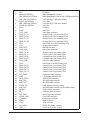
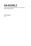
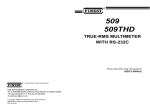
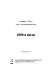
GA-7PESH1 GA-7PESH2 Dual LGA2011 sockets motherboard for Intel® E5-2600 series processors User's Manual Rev. 1001 Copyright © 2012 GIGA-BYTE TECHNOLOGY CO., LTD. All rights reserved. The trademarks mentioned in this manual are legally registered to their respective owners. Disclaimer Information in this manual is protected by copyright laws and is the property of GIGABYTE. Changes to the specifications and features in this manual may be made by GIGABYTE without prior notice. No part of this manual may be reproduced, copied, translated, transmitted, or published in any form or by any means without GIGABYTE's prior written permission. Documentation Classifications In order to assist in the use of this product, GIGABYTE provides the following types of documentations: For quick set-up of the product, read the Quick Installation Guide included with the product. For detailed product information, carefully read the User's Manual. For product-related information, check on our website at: http://www.gigabyte.com Table of Contents Box Contents....................................................................................................................5 GA-7PESH1/7PESH2 Motherboard Layout.....................................................................6 Chapter 1 Hardware Installation......................................................................................9 1-1 1-2 1-3 Installation Precautions..................................................................................... 9 Product Specifications..................................................................................... 10 Installing the CPU and CPU Cooler................................................................ 12 1-3-1 1-3-2 1-4 Installing the Memory...................................................................................... 15 1-4-1 1-4-2 1-4-3 1-5 1-6 1-7 Installing the CPU....................................................................................................12 Installing the CPU Cooler........................................................................................14 Four Channel Memory Configuration......................................................................15 Installing a Memory ................................................................................................16 DIMM Population Table ..........................................................................................16 Back Panel Connectors................................................................................... 17 Internal Connectors......................................................................................... 19 Jumper Setting................................................................................................ 30 Chapter 2 BIOS Setup...................................................................................................35 2-1 2-2 The Main Menu............................................................................................... 37 Advanced Menu.............................................................................................. 39 2-2-1 2-2-2 2-2-3 2-2-4 2-2-5 2-2-6 2-2-7 2-3 Chipset Menu.................................................................................................. 52 2-3-1 2-3-1-1 2-3-1-2 2-3-2 2-3-3 2-4 2-5 North Bridge Configuration......................................................................................53 IOH Configuration....................................................................................................55 DIMM Information....................................................................................................57 South Bridge Configuration.....................................................................................58 ME Subsystem........................................................................................................59 Security Menu................................................................................................. 60 Server Management Menu.............................................................................. 61 2-5-1 2-5-2 2-6 PCI Configuration....................................................................................................40 Trusted Computing (Optioanl).................................................................................41 CPU Configuration...................................................................................................42 Runtime Error Logging............................................................................................46 SATA Configuration.................................................................................................47 Super IO Configuration............................................................................................48 Serial Port Console Redirection.............................................................................50 System Information..................................................................................................62 BMC LAN Configuration..........................................................................................63 Boot Option Menu........................................................................................... 64 -3- 2-7 2-8 Boot Manager.................................................................................................. 66 Exit Menu........................................................................................................ 67 -4- Box Contents Motherboard Driver CD Two SATA cables I/O Shield • The box contents above are for reference only and the actual items shall depend on the product package you obtain. The box contents are subject to change without notice. • The motherboard image is for reference only. -5- GA-7PESH1/7PESH2 Motherboard Layout 51 41 42 44 45 1 47 49 43 46 48 50 2 3 4 5 6 8 9 7 10 11 40 39 38 12 37 36 35 34 33 60 52 59 58 53 13 32 31 30 54 55 57 56 14 29 28 25 24 27 26 19 18 23 22 -6- 21 20 17 16 15 Item 1 2 3 4 5 6 7 8 9 10 11 12 13 14 15 16 17 18 19 20 21 22 23 24 25 26 27 28 29 30 31 32 33 34 35 36 37 38 39 40 41 Code SW1 MLAN (GA-7PESH1) USB_MLAN (GA-7PESH2) USB_LAN1 (GA-7PESH1) GLAN1 (GA-7PESH2) USB_LAN2 (GA-7PESH1) GLAN2 (GA-7PESH2) VGA_1 COM1 P12V_AUX2 DDR3_P1_H1 DDR3_P1_H0 DDR3_P1_G1 DDR3_P1_G0 CPU1 ATX1 PWR_DET1 P12V_AUX1 DDR3_P0_A0 DDR3_P0_A1 DDR3_P0_B0 DDR3_P0_B1 CPU0_FAN CPU0 DDR3_P0_D1 DDR3_P0_D0 DDR3_P0_C1 DDR3_P0_C0 SYS_FAN2 LED2 SATA_SGPIO MINI_CN3 MINI_CN2 FLASH_DP1 MINI_CN1 SATA0/1 BP_1 SYS_FAN1 FRONT_USB F_PANEL1 IPMB1 TPM_1 SKU_KEY1 PCIE_5 Description ID switch BMC Management LAN port BMC Management LAN port (top) / USB ports (bottom) LAN1 port (top) / USB ports (bottom) LAN1 port LAN2 port (top) / USB ports (bottom) LAN2 port VGA port Serial port 8 pin power connector Channel H slot 1 (for secondary CPU) Channel H slot 0 (for secondary CPU) Channel G slot 1 (for secondary CPU) Channel G slot 0 (for secondary CPU) Intel LGA2011 socket (Secondary CPU) 24-pin power connector PM Bus connector 8 pin power connector Channel A slot 0 (for primary CPU) Channel A slot 1 (for primary CPU) Channel B slot 0 (for primary CPU) Channel B slot 1 (for primary CPU) CPU0 fan cable connector Intel LGA2011 socket (Primary CPU) Channel D slot 1 (for primary CPU) Channel D slot 0 (for primary CPU) Channel C slot 1 (for primary CPU) Channel C slot 0 (for primary CPU) System fan cable connector LSI firmware readiness LED SATA SGPIO connector Mini SAS cable connector Mini SAS cable connector Flash descriptor security jumper Mini SAS cable connector (SATA 3.0Gb/s signal) SATA 6.0Gb/s connectors HDD back plane connector System fan cable connector Front USB connector Front panel connector IPMB connector TPM connector PBG A SKU Select connector PCI-E slot 5 (x4 slot / x1 bus) -7- 42 43 44 45 46 47 48 49 50 51 52 53 54 55 56 57 58 59 60 PCIE_4 BMC_LED1 PCIE_3 PCIE_2 PCIE_1 DDR3_P1_E0 DDR3_P1_E1 DDR3_P1_F0 DDR3_P1_F1 CPU1_FAN BAT1 CLR_CMOS1 BIOS_WP1 SSB_ME1 JP1 PASSWORD1 BIOS_RVCR1 SATA_DOM0 SATA_DOM1 PCI-E slot 4 (x16 slot / x8 bus) BMC firmware readiness LED PCI-E slot 3 (x8 slot / x4 bus) PCI-E slot 2 (x16 slot/x16 bus) PCI-E slot 1 (x8 slot / x4 bus) Channel E slot 0 (for secondary CPU) Channel E slot 1 (for secondary CPU) Channel F slot 0 (for secondary CPU) Channel F slot 1 (for secondary CPU) CPU1 fan cable connector Battery Clear CMOS jumper BIOS write protect jumper ME recovery jumper Chassis intrusion jumper Clear password jumper BIOS recovery jumper SATA0 port DOM support jumper SATA1 port DOM support jumper CAUTION! If a SATA type hard drive is connected to the motherboard, please ensure the jumper is closed and set to 2-3 pins (Normal mode), in order to reduce any risk of hard disk damage. Please refer to Page 33 for SATA_DOM0 and SATA_DOM1 jumper setting instruction. -8- Chapter 1 Hardware Installation 1-1 Installation Precautions The motherboard contains numerous delicate electronic circuits and components which can become damaged as a result of electrostatic discharge (ESD). Prior to installation, carefully read the user's manual and follow these procedures: • Prior to installation, do not remove or break motherboard S/N (Serial Number) sticker or warranty sticker provided by your dealer. These stickers are required for warranty validation. • Always remove the AC power by unplugging the power cord from the power outlet before installing or removing the motherboard or other hardware components. • When connecting hardware components to the internal connectors on the motherboard, make sure they are connected tightly and securely. • When handling the motherboard, avoid touching any metal leads or connectors. • It is best to wear an electrostatic discharge (ESD) wrist strap when handling electronic components such as a motherboard, CPU or memory. If you do not have an ESD wrist strap, keep your hands dry and first touch a metal object to eliminate static electricity. • Prior to installing the motherboard, please have it on top of an antistatic pad or within an electrostatic shielding container. • Before unplugging the power supply cable from the motherboard, make sure the power supply has been turned off. • Before turning on the power, make sure the power supply voltage has been set according to the local voltage standard. • Before using the product, please verify that all cables and power connectors of your hardware components are connected. • To prevent damage to the motherboard, do not allow screws to come in contact with the motherboard circuit or its components. • Make sure there are no leftover screws or metal components placed on the motherboard or within the computer casing. • Do not place the computer system on an uneven surface. • Do not place the computer system in a high-temperature environment. • Turning on the computer power during the installation process can lead to damage to system components as well as physical harm to the user. • If you are uncertain about any installation steps or have a problem related to the use of the product, please consult a certified computer technician. -9- Hardware Installation 1-2 Product Specifications CPU Support for Intel® Xeon® E5-2600 series processors in the LGA2011 package L3 cache varies with CPU Supports QuickPath Interconnect up to 8GT/s Enhanced Intel SpeedStep Technology (EIST) Support Intel Virtualization Technology (VT) Chipset Intel® C602 (Patsburg) Chipset Memory 16 x 1.5V DDR3 DIMM sockets supporting up to 128GB (UDIMM) and 512GB (RDIMM) of system memory LAN Expansion Slots Onboard Graphics Storage Interface USB Hardware Installation *Due to Windows 32-bit operating system limitation, when more than 4 GB of physical memory is installed, the actual memory size displayed will be less than 4 GB. 16 x 1.35V DDR3L DIMM sockets supporting up to 128 GB of system memory Four channel memory architecture Support for 800/1066/1333/1600 memory modules Support for ECC RDIMM/ UDIMM memory modules Intel® I350 supports 10/100/1000 Mbps (GA-7PESH1) Intel® X540-AT2 supports dual 10G Base-T ethernet LAN ports (GA-7PESH2) 1 x PCI Express x16 slot, running at x16 (Gen3/PCIE_2) 1 x PCI Express x16 slot, running at x8 (Gen3/PCIE_4) 2 x PCI Express x8 slot, running at x4 (Gen3/PCIE_1/PCIE_3) 1 x PCI Express x4 slot, running at x1 (Gen2/PCIE_5) ASPEED ® AST2300 supports 16MB VRAM Intel® C602 controller 2 x SATA 6Gb/s connectors (SATA0/1) 1 x SAS 3Gb/s connector (4 additional ports via the SATA brackets connected to the internal SAS headers) 2 x SAS 6Gb/s connectors (8 additional ports via the SAS brackets connected to the internal SAS headers) Support for Intel RSTe SATA RAID 0, RAID 1 Up to 6 USB 2.0/1.1 ports (4 on the back panel, 2 additional ports via the USB brackets connected to the internal USB headers/GA-7PESH1) Up to 4 USB 2.0/1.1 ports (2 on the back panel, 2 additional ports via the USB brackets connected to the internal USB headers/GA-7PESH2) - 10 - Internal Connectors Rear Panel I/O 1 x 24-pin ATX main power connector 2 x 8-pin ATX 12V power connector 2 x Mini SAS connectors (SAS 6Gb/s signal) 1 x Mini SAS connector (SATA 3Gb/s signal) 2 x SATA 6Gb/s connectors 1 x PSMI header 2 x CPU fan header 2 x System fan header 1 x Front panel header 1 x Back panel header 1 x USB 2.0/1.1 header 1 x TPM header 1 x SKU KEY header 1 x SPGIO header 4 x USB 2.0/1.1 ports (GA-7PESH1) 2 x USB 2.0/1.1 ports (GA-7PESH2) 3 x RJ-45 port 1 x COM port 1 x VGA port 1 x ID Switch button I/O Controller ASPEED ® AST2300 BMC chip Hardware Monitor System voltage detection CPU/System temperature detection CPU/System fan speed detection CPU/System fan speed control BIOS Form Factor *Whether the CPU/system fan speed control function is supported will depend on the CPU/system cooler you install. 1 x 64 Mbit flash AMI BIOS EATX Form Factor; 12 inch x 13 inch, 8 layers PCB * GIGABYTE reserves the right to make any changes to the product specifications and product-related information without prior notice. - 11 - Hardware Installation 1-3 Installing the CPU and CPU Cooler Read the following guidelines before you begin to install the CPU: • Make sure that the motherboard supports the CPU. (Go to GIGABYTE's website for the latest CPU support list.) • Always turn off the computer and unplug the power cord from the power outlet before installing the CPU to prevent hardware damage. • Locate the pin one of the CPU. The CPU cannot be inserted if oriented incorrectly. (Or you may locate the notches on both sides of the CPU and alignment keys on the CPU socket.) • Apply an even and thin layer of thermal grease on the surface of the CPU. • Do not turn on the computer if the CPU cooler is not installed, otherwise overheating and damage of the CPU may occur. • Set the CPU host frequency in accordance with the CPU specifications. It is not recommended that the system bus frequency be set beyond hardware specifications since it does not meet the standard requirements for the peripherals. If you wish to set the frequency beyond the standard specifications, please do so according to your hardware specifications including the CPU, graphics card, memory, hard drive, etc. 1-3-1 Installing the CPU A. Locate the alignment keys on the motherboard CPU socket and the notches on the CPU. Pin One Corner of the CPU Socket Alignment Key Alignment Key LGA2011 CPU Hardware Installation - 12 - Notch Notch Notch Notch Triangle Pin One Marking on the CPU B. Follow the steps below to correctly install the CPU into the motherboard CPU socket. •• Before installing the CPU, make sure to turn off the computer and unplug the power cord from the power outlet to prevent damage to the CPU. •• To protect the socket contacts, do not remove the protective plastic cover unless the CPU is inserted into the CPU socket. Save the cover properly and replace it if the CPU is removed. Lever A Lever B Step 1: Push the lever closest to the "unlock" marking " " (below referred as lever A) down and away from the socket to release it. Step 2: Push the lever closest to the "lock" marking " " (below referred as lever B) down and away from the socket. Then lift the lever. Step 3: Gently press lever A to allow the load plate to rise. Open the load plate. (Note: DO NOT touch the socket contacts after the load plate is opened.) Step 5: Once the CPU is properly inserted, carefully replace the load plate. Then secure lever B under its retention tab. The protective plastic cover may pop off from the load plate during the process of engaging the lever. Remove the cover. Save the cover properly and always replace it when the CPU is not installed. Step 4: Hold the CPU with your thumb and index fingers. Align the CPU pin one marking (triangle) with the pin one corner of the CPU socket (or align the CPU notches with the socket alignment keys) and carefully insert the CPU into the socket vertically. Step 6: Finally, secure lever A under its retention tab to complete the installation of the CPU. - 13 - Hardware Installation 1-3-2 Installing the CPU Cooler Refer to the steps below to correctly install the CPU cooler on the motherboard. (Actual installation process may differ depending the CPU cooler to be used. Refer to the user's manual for your CPU cooler.) Step 1: Apply an even and thin layer of thermal grease on the surface of the installed CPU. Step 2: Place the cooler atop the CPU, aligning the four mounting screws with the mounting holes on the ILM. (If your cooler has a fan grill which may cause interference when you tighten the screws, remove it first and replace it after tightening the screws.) Step 3: Use one hand to hold the cooler and the other to tighten the screws in a diagonal sequence with a screw driver. Begin tightening a screw with a few turns and repeat with the screw diagonally opposite the one you just tightened. Then do the same to the other pair. Next, fully tighten the four screws. Step 4: Finally, attach the power connector of the CPU cooler to the CPU fan header (CPU_FAN) on the motherboard. Please pay more attention when removing the CPU cooler because the thermal grease/tape between the CPU cooler and CPU may adhere to the CPU. Inadequately removing the CPU cooler may damage the CPU. Hardware Installation - 14 - 1-4 Installing the Memory Read the following guidelines before you begin to install the memory: • Make sure that the motherboard supports the memory. It is recommended that memory of the same capacity, brand, speed, and chips be used. (Go to GIGABYTE's website for the latest supported memory speeds and memory modules.) • Always turn off the computer and unplug the power cord from the power outlet before installing the memory to prevent hardware damage. • Memory modules have a foolproof design. A memory module can be installed in only one direction. If you are unable to insert the memory, switch the direction. 1-4-1 Four Channel Memory Configuration DDR3_P1_G1 DDR3_P1_G0 DDR3_P1_H1 DDR3_P1_H0 DDR3_P0_A1 DDR3_P0_B1 DDR3_P0_B0 DDR3_P0_A0 DDR3_P1_F0 DDR3_P1_F1 DDR3_P0_D0 DDR3_P0_D1 DDR3_P0_C1 DDR3_P0_C0 DDR3_P1_E1 DDR3_P1_E0 This motherboard provides eight DDR3 memory sockets and supports Four Channel Technology. After the memory is installed, the BIOS will automatically detect the specifications and capacity of the memory. Enabling Four Channel memory mode will be four times of the original memory bandwidth. The four DDR3 memory sockets are divided into four channels each channel has two memory sockets as following: Channel 1: DDR3_P0_A0, DDR3_P0_A1 (For pimary CPU) DDR3_P0_E0, DDR3_P0_E1 (For secondary CPU) Channel 2: DDR3_P0_B0, DDR3_P0_B1(For pimary CPU) DDR3_P0_F0, DDR3_P0_F1 (For secondary CPU) Channel 3: DDR3_P0_C0, DDR3_P0_C1(For pimary CPU) DDR3_P0_G0, DDR3_P0_G1 (For secondary CPU) Channel 4: DDR3_P0_D0, DDR3_P0_D1(For pimary CPU) DDR3_H0_F0, DDR3_P0_H1 (For secondary CPU) Due to CPU limitations, read the following guidelines before installing the memory in Four Channel mode. 1. Four Channel mode cannot be enabled if only one DDR3 memory module is installed. 2. When enabling Four Channel mode with two or four memory modules, it is recommended that memory of the same capacity, brand, speed, and chips be used for optimum performance. - 15 - Hardware Installation 1-4-2 Installing a Memory Before installing a memory module, make sure to turn off the computer and unplug the power cord from the power outlet to prevent damage to the memory module. Be sure to install DDR3 DIMMs on this motherboard. Installation Step: Step 1. Insert the DIMM memory module vertically into the DIMM slot, and push it down. Step 2. Close the plastic clip at both edges of the DIMM slots to lock the DIMM module. Note: For dual-channel operation, DIMMs must be installed in matched pairs. Step 3. Reverse the installation steps when you wish to remove the DIMM module. 1 2 2 1-4-3 DIMM Population Table 1N or 2N DIMM1 DIMM0 1N or 2N DIMM1 DIMM0 1N Empty Single-Rank 1N Empty Single-Rank 1N Empty Dual-Rank 1N Empty Quad-Rank 1N Single-Rank 1N Single-Rank 1N Dual-Rank Dual-Rank 1N Single-Rank Quad-Rank 1N Dual-Rank Quad-Rank 1N Quad-Rank Quad-Rank R-DIMM Hardware Installation 1N Empty Dual-Rank 2N Single-Rank Single-Rank Single-Rank 2N Single-Rank Dual-Rank Dual-Rank 2N Dual-Rank Dual-Rank U-DIMM - 16 - 1-5 Back Panel Connectors GA-7PESH1 GA-7PESH2 Serial Port Connects to serial-based mouse or data processing devices. Video Port The video in port allows connect to video in, which can also apply to video loop thru function. RJ-45 LAN Port (Gigabit Ethernet LAN Port) The Gigabit Ethernet LAN port provides Internet connection at up to 1 Gbps data rate. The following describes the states of the LAN port LEDs. RJ-45 LAN Port (10 Gigabit Ethernet LAN Port) The 10 Gigabit Ethernet LAN port provides Internet connection at up to 10 Gbps data rate. The following describes the states of the LAN port LEDs. KVM Server Management 10/100 LAN Port The LAN port provides Internet connection with data transfer speeds of 10/100Mbps. USB 2.0/1.1 Port The USB port supports the USB 2.0/1.1 specification. Use this port for USB devices such as a USB keyboard/mouse, USB printer, USB flash drive and etc. ID Switch Button This button provide the selected unit idenfication function. - 17 - Hardware Installation Speed LED Link Activity LED MLAN Speed LED: State Green On Green Blink 10/100 LAN Port Speed LED Link Activity LED 10/100/1000 LAN Port Off I350 Speed LED: State Yellow On Yellow Blink Green On Green Blink Off Speed LED Link Activity LED 10/100/1000/10G LAN Port Link/Activity LED: Description 100 Mbps data rate 10 Mbps or 100 Mbps data rate 10 Mbps data rate Yellow On Yellow Blink Off Description Link bet ween system and net work or no access Blinking Data transmission or receiving is occurring Off No data transmission or receiving is occurring Link/Activity LED: Description 1 Gbps data rate Identif y 1 Gbps data rate 100 Mbps data rate Identify 100 Mbps data rate 10 Mbps data rate State On Description 10 Gbps data rate Identify 10 Gbps data rate 1 Gbps data rate Identif y 1 Gbps data rate 10 Mbps or 100 Mbps data rate State On X540 Speed LED: State Green On Green Blink State On Description Link bet ween system and net work or no access Blinking Data transmission or receiving is occurring Off No data transmission or receiving is occurring Link/Activity LED: Description Link bet ween system and net work or no access Blinking Data transmission or receiving is occurring Off No data transmission or receiving is occurring • When removing the cable connected to a back panel connector, first remove the cable from your device and then remove it from the motherboard. • When removing the cable, pull it straight out from the connector. Do not rock it side to side to prevent an electrical short inside the cable connector. • Inlet airflow over 10G LAN chipset heat sink require at least 2 cubic feet per minute (CFM) else the heat sink temperature will continue to rise while 10G LAN starts functioning. (Location indicated by red arrow) Hardware Installation - 18 - 1-6 Internal Connectors 22 6 2 19 15 17 16 10 7 14 20 9 1 11 12 4 13 18 3 21 8 1) 2) 3) 4) 5) 6) 7) 8) 9) 10) 11) ATX1 P12V_AUX2 P12V_AUX1 PWR_DET1 CPU0_FAN (forprimary CPU) CPU1_FAN (for seconary CPU) SYS_FAN1 (System Fan) SYS_FAN2 (System Fan) SATA0/1 FRONT_USB MINII_CN1 5 12) 13) 14) 15) 16) 17) 18) 19) 20) 21) 22) - 19 - MINII_CN2 MINII_CN3 BP_1 TPM_1 F_PANEL1 IPMB1 SATA_SGPIO SKU_KEY1 BAT1 LED2 BMC_LED1 Hardware Installation Read the following guidelines before connecting external devices: • First make sure your devices are compliant with the connectors you wish to connect. • Before installing the devices, be sure to turn off the devices and your computer. Unplug the power cord from the power outlet to prevent damage to the devices. • After installing the device and before turning on the computer, make sure the device cable has been securely attached to the connector on the motherboard. Hardware Installation - 20 - 1/2/3)ATX1/P12V_AUX2/P12V_AUX1 (2x4 12V Power Connector and 2x12 Main Power Connector) With the use of the power connector, the power supply can supply enough stable power to all the components on the motherboard. Before connecting the power connector, first make sure the power supply is turned off and all devices are properly installed. The power connector possesses a foolproof design. Connect the power supply cable to the power connector in the correct orientation. The 12V power connector mainly supplies power to the CPU. If the 12V power connector is not connected, the computer will not start. To meet expansion requirements, it is recommended that a power supply that can withstand high power consumption be used (500W or greater). If a power supply is used that does not provide the required power, the result can lead to an unstable or unbootable system. P12V_AUX1 4 8 1 5 P12V_AUX2 ATX 1 8 4 P12V_AUX2 Pin No. 1 2 3 4 5 6 7 8 Definition GND GND GND GND +12V +12V +12V +12V ATX1 13 24 ATX_12V 5 P12V_AUX1 1 12 ATX1 Pin No. 1 2 3 4 5 6 7 8 9 10 11 12 Definition 3.3V 3.3V GND +5V GND +5V GND Power Good 5VSB (stand by +5V) +12V +12V 3.3V - 21 - Pin No. 13 14 15 16 17 18 19 20 21 22 23 24 Definition 3.3V -12V GND PS_ON GND GND GND -5V +5V +5V +5V GND Hardware Installation 4) PWR_DET1 (Power management connector) Pin No. 1 2 3 4 5 1 5 Definition SMB CLK SMB DATA SMB Alert GND 3.3V Sense 5/6/7/8) CPU0_FAN/CPU1_FAN/SYS_FAN1/SYS_FAN2 (CPU Fan/System Fan Headers) The motherboard has a 4-pin CPU fan header (CPU_FAN1/2), a 4-pin (FAN4) system fan headers. Most fan headers possess a foolproof insertion design. When connecting a fan cable, be sure to connect it in the correct orientation (the black connector wire is the ground wire). The motherboard supports CPU fan speed control, which requires the use of a CPU fan with fan speed control design. For optimum heat dissipation, it is recommended that a system fan be installed inside the chassis. CPU1_FAN 1 CPU0_FAN 1 CPU1_FAN 1 Pin No. 1 2 3 4 Definition GND +12V Sense Speed Control SYS_FAN2 1 SYS_FAN1 SYS_FAN2 SYS_FAN1 CPU0_FAN • Be sure to connect fan cables to the fan headers to prevent your CPU and system from overheating. Overheating may result in damage to the CPU or the system may hang. • These fan headers are not configuration jumper blocks. Do not place a jumper cap on the headers. Hardware Installation - 22 - 9) SATA0/SATA1 (SATA 6Gb/s Connectors) The SATA connectors conform to SATA 6Gb/s standard and are compatible with SATA 3Gb/s and 1.5Gb/s standard. Each SATA connector supports a single SATA device. When SATA_DOM1/2 jumper are set to Normal Mode: 1 1 SATA1 7 SATA0 7 Pin No. 1 2 3 4 5 6 7 Definition GND TXP TXN GND RXN RXP GND When SATA_DOM1/2 Jumper are set to 1-2 pin: G.QBOFM Pin No. 1 2 3 4 5 6 7 Definition GND TXP TXN GND RXN RXP P5V • A RAID 0 or RAID 1 configuration requires at least two hard drives. If more than two hard drives are configured, the total number of hard drives must be an even number. •A RAID 10 configuration requires four hard drives. (Note) When a RAID configuration is built across the SATA 6Gb/s channels, the system performance of the RAID configuration may vary depends on the devices are connected. 10) FRONT_USB (Front USB Headers) The headers conform to USB 2.0/1.1 specification. Each USB header can provide two USB ports via an optional USB bracket. For purchasing the optional USB bracket, please contact the local dealer. - 23 - 1 2 9 10 Pin No. 1 2 3 4 5 6 7 8 9 10 Definition Power (5V) Power (5V) USB DXUSB DYUSB DX+ USB DY+ GND GND No Pin NC Hardware Installation 11) MINI_CN1 (Mini SAS cable connector with SATA 3Gb/s signal) The SATA connectors conform to SATA 3Gb/s standard and are compatible with SATA 1.5Gb/s standard. Each SATA connector supports two SATA device. 12/13) MINI_CN2/MINI_CN3 (Mini SAS cable connectors) The mini SAS connectors conform to SAS 6Gb/s standard. A1 B1 A18 B18 MINI_CN1 MINI_CN2 MINI_CN3 MINI_CN1 MINI_CN2 MINI_CN3 Pin No. A1 A2 A3 A4 A5 A6 A7 A8 A9 A10 A11 A12 A13 A14 A15 A16 A17 A18 Definition GND RX0+ RX0GND RX1+ RX1GND SIB7 SIB3 SIB4 SIB5 GND RX2+ RX2GND RX3+ RX3GND Hardware Installation Pin No. B1 B2 B3 B4 B5 B6 B7 B8 B9 B10 B11 B12 B13 B14 B15 B16 B17 A18 Definition GND TX0+ TX0GND TX1+ TX1GND SIB0 SIB1 SIB2 SIB6 GND TX2+ TX2GND TX3+ TX3GND Pin No. A1 A2 A3 A4 A5 A6 A7 A8 A9 A10 A11 A12 A13 A14 A15 A16 A17 A18 - 24 - Definition GND RX0+ RX0GND RX1+ RX1GND SIB7 SIB3 SIB4 SIB5 GND RX2+ RX2GND RX3+ RX3GND Pin No. B1 B2 B3 B4 B5 B6 B7 B8 B9 B10 B11 B12 B13 B14 B15 B16 B17 A18 Definition GND TX0+ TX0GND TX1+ TX1GND SIB0 SIB1 SIB2 SIB6 GND TX2+ TX2GND TX3+ TX3GND 14) BP_1 (HDD Back Plane Board Hearder) 1 2 25 26 Pin No. 1 2 3 4 5 6 7 8 9 10 11 12 13 14 15 16 17 18 19 20 21 22 23 24 25 26 Definition AST2300_SCGCLK FM_THROTTLE_AND_N AST2300_SGLD IQO_FAN_12v_GATE_N AST2300_SGDOUT GND KEY RresetL_BRB GND BP_ALED_N BP_LED_G_N GND AST2300_SGDIN ASSESS#_LED_BPB GND SMB_BPB1_DATA GND SMB_BPB1_CLK P_3V3_AUX BP_HDD_TYPE P_3V3_AUX FAN_TYPE GND KEY BP_PRESENSE GND 15) TPM_1 (TPM Module Connector) 1 2 13 14 - 25 - Pin No. 1 2 3 4 5 6 7 8 9 10 11 12 13 14 Definition CLK_33M_TPM P_3V3_AUX LPC_RST_DEBUG P3V3 LPC_LAD0 IRQ_SERIAL LPC_LAD1 TPM_DET_N LPC_LAD2 NC LPC_LAD3 GND LPC_FRAME_N GND Hardware Installation 16) F_Panel1 (Front Panel Header) Connect the power switch, reset switch, speaker, chassis intrusion switch/sensor and system status indicator on the chassis to this header according to the pin assignments below. Note the positive and negative pins before connecting the cables. 1 2 23 24 Pin No. 1 2 3 4 5 6 7 8 9 10 11 12 13 14 15 16 17 18 19 20 21 22 23 24 Signal Name PWLED+ 5VSB NC ID_LED+ PWLED- ID_LED- HD+ F_SYSRDY HD- SYS_STATUS- PWB+ L1_ACT PWB+_GND L1_LINK- RST_BTN+ SENSOR_SDA RST_BTN_GND SENSOR_SCL ID_SW+ CASE_OPEN- ID_SW (GND) L2_ACT NMI_SW- L2_LINK- Definition Power LED Signal anode (+) 5V Stanndby Power No Pin ID LED Signal anode (+) Power LED Signal cathode(-) ID LED Signal cathode(-) Hard Disk LED Signal anode (+) System Front board LED Signal Hard Disk LED Signal cathode(-) System Status LED Signal cathode(-) Power Button Signal anode (+) LAN1 active LED Signal Ground LAN1 Link LED Signal cathode(-) Reset button Signal anode (+) SMBus Data Signal Ground SMBus Clock Signal ID Switch Signal anode (+) Chassis intrusion Signal cathode(-) Ground LAN2 active LED Signal NMI switch Signal cathode(-) LAN2 Link LED Signal cathode(-) The front panel design may differ by chassis. A front panel module mainly consists of power switch, reset switch, power LED, hard drive activity LED, speaker and etc. When connecting your chassis front panel module to this header, make sure the wire assignments and the pin assignments are matched correctly. Hardware Installation - 26 - 17) IPMB1 (IPMB connector) 3 Pin No. 1 2 3 1 Definition SCL GND SDA 18) SATA_SGPIO (SATA SGPIO Header) SGPIO is stands for Serial General Purpose Input/Output which is a 4-signal (or 4-wire) bus used between a Host Bus Adapter (HBA) and a backplane. Out of the 4 signals, 3 are driven by the HBA and 1 is driven by the backplane. Typically, the HBA is a storage controller located inside a server, desktop, rack or workstation computer that interfaces with Hard disk drives (HDDs) to store and retrieve data. 7 8 1 2 - 27 - Pin No. 1 2 3 4 5 6 7 8 Definition SGPIO_SATA_DATAIN No Pin SGPIO_SATA_DATAOUT GND GND SGPIO_SATA_LOAD NC SGPIO_SATA_CLOCK Hardware Installation 19) SKU_KEY1 (Patsburg Upgrade ROM Hearder) 1 3 Pin No. 1 2 3 Definition GND FM_PBG_DYN_SKU_KEY GND 20) BAT1 (Battery) The battery provides power to keep the values (such as BIOS configurations, date, and time information) in the CMOS when the computer is turned off. Replace the battery when the battery voltage drops to a low level, or the CMOS values may not be accurate or may be lost. You may clear the CMOS values by removing the battery: 1. Turn off your computer and unplug the power cord. 2. Gently remove the battery from the battery holder and wait for one minute. (Or use a metal object like a screwdriver to touch the positive and negative terminals of the battery holder, making them short for 5 seconds.) 3. Replace the battery. 4. Plug in the power cord and restart your computer. • Always turn off your computer and unplug the power cord before replacing the battery. • Replace the battery with an equivalent one. Danger of explosion if the battery is replaced with an incorrect model. • Contact the place of purchase or local dealer if you are not able to replace the battery by yourself or uncertain about the battery model. • When installing the battery, note the orientation of the positive side (+) and the negative side (-) of the battery (the positive side should face up). • Used batteries must be handled in accordance with local environmental regulations. Hardware Installation - 28 - 21) LED2 (LSI Firmware Readiness LED) LED2 Link/Activity: State Description Blinking LSI firmware is ready Off LSI firmware is not ready 22) BMC_LED1 (BMC Firmware Readiness LED) State On Blinking Off - 29 - Description BMC firmware is initial BMC firmware is ready System is powered off Hardware Installation 1-7 Jumper Setting 8 7 1 2 6 3 9 1) 2) 3) 4) 5) CLR_CMOS1 BIOS_WP1 SSB_ME1 JP1 PASSWORD1 Hardware Installation 5 4 6) 7) 8) 9) - 30 - BIOS_RCVR1 SATA_DOM0 SATA_DOM1 FLASH_DP1 1) CLR_CMOS1 (Clearing CMOS Jumper) Use this jumper to clear the CMOS values (e.g. date information and BIOS configurations) and reset the CMOS values to factory defaults. To clear the CMOS values, place a jumper cap on the two pins to temporarily short the two pins or use a metal object like a screwdriver to touch the two pins for a few seconds. 1 1-2 Close: Normal operation (Default setting) 1 2-3 Close: Clear CMOS data. • Always turn off your computer and unplug the power cord from the power outlet before clearing the CMOS values. • After clearing the CMOS values and before turning on your computer, be sure to remove the jumper cap from the jumper. Failure to do so may cause damage to the motherboard. • After system restart, go to BIOS Setup Exit menu and load factory defaults (select Load Default Values) or manually configure the BIOS settings (refer to Chapter 2, "BIOS Setup," for BIOS configurations). 2) BIOS_WP1 (BIOS Write Protect Jumper) 1 1-2 Close: Normal operation. (Default setting) 1 2-3 Close: Enable BIOS write protect function. - 31 - Hardware Installation 3) SSB_ME1 (ME enable/disable Jumper) SSB_ME1 1 1-2 Close: Normal operation. (Default setting) 1 2-3 Close: Disable ME function. 4) JP5 (Case Open Intrusion Jumper) Open: Enable chassis intrusion alert. Close: Normal operation. (Default setting) Hardware Installation - 32 - 5) PASSWORD1 (Skip Supervisor Password Jumper) 1 1-2 Close: Normal operation. (Default setting) 1 2-3 Close: Skip supervisor password. 6) BIOS_RVCR1 (BIOS Recovery Jumper) 1 1-2 Close: Normal operation. (Default setting) 1 2-3 Close: BIOS recovery mode. - 33 - Hardware Installation 7/8)SATA_DOM0/1 (SATA DOM Jumper) CAUTION! If a SATA type hard drive is connected to the motherboard, please ensure the jumper is closed and set to 2-3 pins (Normal mode), in order to reduce any risk of hard disk damage. 1 1-2 Close: Enable SATA0/SATA1 port DOM support. 1 2-3 Close: Normal mode. (Default setting) 9) FLASH_DP1 (Flash Descriptor Security Jumper) 1 1-2 Close: Flash Descriptor Security Overridden 1 2-3 Close: Flash Descriptor Security in effect. (Default setting) Hardware Installation - 34 - Chapter 2 BIOS Setup BIOS (Basic Input and Output System) records hardware parameters of the system in the EFI on the motherboard. Its major functions include conducting the Power-On Self-Test (POST) during system startup, saving system parameters and loading operating system, etc. BIOS includes a BIOS Setup program that allows the user to modify basic system configuration settings or to activate certain system features. When the power is turned off, the battery on the motherboard supplies the necessary power to the CMOS to keep the configuration values in the CMOS. To access the BIOS Setup program, press the <F2> key during the POST when the power is turned on. • BIOS flashing is potentially risky, if you do not encounter problems of using the current BIOS version, it is recommended that you don't flash the BIOS. To flash the BIOS, do it with caution. Inadequate BIOS flashing may result in system malfunction. • It is recommended that you not alter the default settings (unless you need to) to prevent system instability or other unexpected results. Inadequately altering the settings may result in system's failure to boot. If this occurs, try to clear the CMOS values and reset the board to default values. (Refer to the "Load Optimized Defaults" section in this chapter or introductions of the battery/ clearing CMOS jumper in Chapter 1 for how to clear the CMOS values.) BIOS Setup Program Function Keys <f><g> Move the selection bar to select the screen <h><i> Move the selection bar to select an item <Enter> Execute command or enter the submenu <Esc> Main Menu: Exit the BIOS Setup program Submenus: Exit current submenu <F1> Show descriptions of general help <F3> Restore the previous BIOS settings for the current submenus <F9> Load the Optimized BIOS default settings for the current submenus <F10> Save all the changes and exit the BIOS Setup program - 35 - BIOS Setup Main This setup page includes all the items in standard compatible BIOS. Advanced This setup page includes all the items of AMI BIOS special enhanced features. (ex: Auto detect fan and temperature status, automatically configure hard disk parameters.) Chipset This setup page includes all the submenu options for configuring the function of North Bridge and South Bridge. (ex: Auto detect fan and temperature status, automatically configure hard disk parameters.) Security Change, set, or disable supervisor and user password. Configuration supervisor password allows you to restrict access to the system and BIOS Setup. A supervisor password allows you to make changes in BIOS Setup. A user password only allows you to view the BIOS settings but not to make changes. Server additional features enabled/disabled setup menus. This setup page provides items for configuration of boot sequence. This setup page provides configuration of boot up devices. Server Management Boot Options Boot Manager Exit Save all the changes made in the BIOS Setup program to the CMOS and exit BIOS Setup. (Pressing <F10> can also carry out this task.) Abandon all changes and the previous settings remain in effect. Pressing <Y> to the confirmation message will exit BIOS Setup. (Pressing <Esc> can also carry out this task.) BIOS Setup - 36 - 2-1 The Main Menu Once you enter the BIOS Setup program, the Main Menu (as shown below) appears on the screen. Use arrow keys to move among the items and press <Enter> to accept or enter other sub-menu. Main Menu Help The on-screen description of a highlighted setup option is displayed on the bottom line of the Main Menu. Submenu Help While in a submenu, press <F1> to display a help screen (General Help) of function keys available for the menu. Press <Esc> to exit the help screen. Help for each item is in the Item Help block on the right side of the submenu. • When the system is not stable as usual, select the Load Default Values item to set your system to its defaults. • The BIOS Setup menus described in this chapter are for reference only and may differ by BIOS version. - 37 - BIOS Setup BIOS Information BIOS Version Display version number of the BIOS setup utility. Memory Information Total Memory Determines how much total memory is present during the POST. System Date Set the date following the weekday-month-day- year format. System Time Set the system time following the hour-minute- second format. Access Level Display the current accessing level information. BIOS Setup - 38 - 2-2 Advanced Menu The Advanced menu display submenu options for configuring the function of various hardware components. Select a submenu item, then press Enter to access the related submenu screen. - 39 - BIOS Setup 2-2-1 PCI Configuration PCI Express Slot 1/2/3/4/5 Option ROM When enabled, This setting will initialize the device expansion ROM for the related PCI-E slot. Options available: Enabled/Disabled. Default setting is Enabled. Onboard LSI Option ROM Enable/Disable onboard LSI option ROM. Options available: Enabled/Disabled. Default setting is Enabled. Onboard LAN1/2 Controller Enable/Disable Onboard LAN controller . Options available: Enabled/Disabled. Default setting is Enabled. LAN1/2 Option ROM Enable/Disable onboard LAN1 device and initialize device expansion ROM. Options available: Enabled/Disabled. Default setting is Disabled. PERR Generation When this item is set to enabled, PCI bus parity error (PERR) is generated and is routed to NMI. Options available: Enabled/Disabled. Default setting is Disabled. SERR Generation When this item is set to enabled, PCI bus system error (SERR) is generated and is routed to NMI. Options available: Enabled/Disabled. Default setting is Disabled. BIOS Setup - 40 - 2-2-2 Trusted Computing (Optioanl) TPM Support Select Enabled to activate TPM support feature. Options available: Enabled/Disabled. Default setting is Enabled. TPM State (Note) Select Enabled to activate TPM State function. Options available: Enabled/Disabled. Default setting is Enabled. Pending Operation (Note) Determine the action when operation is pending. Options available: None. Default setting is None. Current Status Information Display current TPM status information. (Note) This item appears when the TPM module is attached. - 41 - BIOS Setup 2-2-3 CPU Configuration BIOS Setup - 42 - - 43 - BIOS Setup Socket 0/1 Information CPU Signature Displays the processor ID information. Microcode Patch Display Microcode patch. Max CPU Speed Display the maximum processor speed. Min CPU Speed Display the minimum processor speed. Processor Cores Display the information of the processor core. Intel HT Technology Display Intel Hyper Threading Technology function support information. Intel VT-x Technology Display Intel Virtualization Technology function support information. Cache Information L1 Data Cache Display the information of L1 Data Cache. L1 Code Cache Display the information of L1 Code Cache. L2 Cache Display the information of L2 Cache per Core. L3 Cache Display the information of total L3 Cache per socket. Hyper Threading The Intel Hyper Threading Technology allows a single processor to execute two or more separate threads concurrently. When hyper-threading is enabled, multi-threaded software applications can execute their threads, thereby improving performance. Options available: Enabled/Disabled. Default setting is Enabled. Active Processor Cores (Note) Allows you to determine whether to enable all CPU cores. Options available: All/1. Default setting is All. Limit CPUID Maximum When enabled, the processor will limit the maximum COUID input values to 03h when queried, even if the processor suppports a higher CPUID input value. When disabled, the processor will return the actual maximum CPUID input value of the processor when queried. Options available: Enabled/Disabled. Default setting is Enabled. (Note) This item is present only if you install a CPU that supports this feature. For more information about Intel CPUs' unique features, please visit Intel's website. BIOS Setup - 44 - Execute Disable Bit When enabled, the processor prevents the execution of code in data-only memory pages. This provides some protection against buffer overflow attacks. When disabled, the processor will not restrict code execution in any memory area. This makes the processor more vulnerable to buffer overflow attacks. Options available: Enabled/Disabled. Default setting is Enabled. Energy Performace Optimize between performance and power savings. Windows 2008 and later OSes overrides this value according to its power plan. Options available: Performace/Balanced Performace/Balanced Energy/ Energy Efficient. Default setting is Balanced Performace. Intel Virtualization Technology Select whether to enable the Intel Virtualization Technology function. VT allows a single platform to run multiple operating systems in independent partitions. Options available: Enabled/Disabled. Default setting is Enabled. CPU Management Power Technology Configure the power management features. Options available: Disable/Energy Efficient/Custom. Default setting is Energy Efficient. - 45 - BIOS Setup 2-2-4 Runtime Error Logging Runtime Error Logging Support Enable/Disable Runtime error logging support. Options available: Enabled/Disabled. Default setting is Enabled. BIOS Setup - 46 - 2-2-5 SATA Configuration SATA Port 0/1/2/3/4/5 (Note) Displays the installed HDD devices information. SATA Mode Select the on chip SATA type. IDE Mode: When set to IDE, the SATA controller disables its RAID and AHCI functions and runs in the IDE emulation mode. This is not allowed to access RAID setup utility. RAID Mode: When set to RAID, the SATA controllerenables both its RAID and AHCI functions. You will be allows access the RAID setup utility at boot time. AHCI Mode: When set to AHCI,the SATA controller enables its AHCI functionality. Then the RAID function is disabled and cannot be access the RAID setup utility at boot time. Options available: IDE/RAID/AHCI/Disabled. Default setting is AHCI Mode. (Note) This item is will not appear when the SATA mode is set ot RAID mode. - 47 - BIOS Setup 2-2-6 Super IO Configuration BIOS Setup - 48 - Serial Port 1 Configuration Serial Port 1 When enabled allows you to configure the serial port settings. When set to Disabled, displays no configuration for the serial port. Options available: Enabled/Disabled. Default setting is Enabled. Device Settings Displays the Serial Port 1/2 base I/O addressand IRQ. Change Settings Change Serial Port 1/2 device settings. When set to Auto allows the server’s BIOS or OS to select a configuration. Options available: Auto/IO=3F8; IRQ=4/IO=3F8h; IRQ=3,4,5,6,7,10,11,12/ IO=2F8h; IRQ=3,4,5,6,7,10,11,12 /IO=3E8h; IRQ=3,4,5,6,7,10,11,12/IO=2E8h; IRQ=3,4,5,6,7,10,11,12. Device Mode Change the Serial Port mode. Options available: Standard Serial Port Mode (Normal Mode)/IrDA 1.0 (HP SIR) Mode (High Speed)/ ASKIRfdgdg Mode. - 49 - BIOS Setup 2-2-7 Serial Port Console Redirection BIOS Setup - 50 - Console Redirection (Note) Select whether to enable console redirection for specified device. Console redirection enables users to manage the system from a remote location. Options available: Enabled/Disabled. Default setting is Disabled. Terminal Type Select a terminal type to be used for console redirection. Options available: VT100/VT100+/ANSI /VT-UTF8. Bits per second Select the baud rate for console redirection. Options available: 9600/19200/57600/115200. Data Bits Select the data bits for console redirection. Options available: 7/8. Parity A parity bit can be sent with the data bits to detect some transmission errors. Even: parity bi is 0 if the num of 1's in the data bits is even. Odd: parity bit is0if num of 1's the data bits is odd. Mark: parity bit is always 1. Space: Parity bit is always 0. Mark and Space Parity do not allow for error detection. Options available: None/Even/Odd/Mark/Space. Stop Bits Stop bits indicate the end of a serial data packet. (A start bit indicates the beginning). The standard setting is 1 stop bit. Communication with slow devices may require more than 1 stop bit. Options available: 1/2. Flow Control Flow control can prevent data loss from buffer overflow. When sending data, if the receiving buffers are full, a 'stop' signal can be sent to stop the data flow. Once the buffers are empty, a 'start' signal can be sent to re-start the flow. Hardware flow control uses two wires to send start/stop signals. Options available: None/Hardware RTS/CTS. VT-UTF8 Combo Key Support Enable/Disable VT-UTF8 Combo Key Support. Options available: Enabled/Disabled. Default setting is Enabled. BMC SOL Serial Port Switch When enabled, COM1 Switch to AST2300 SOL UART. When disabled, COM1 Switch to IT8728 SOL UART. Options available: Enabled/Disabled. (Note) Advanced items prompt when this item is defined. - 51 - BIOS Setup 2-3 Chipset Menu The Chipset menu display submenu options for configuring the function of North Bridge and South Bridge. Select a submenu item, then press Enter to access the related submenu screen. BIOS Setup - 52 - 2-3-1 North Bridge Configuration Compatibility RID Enable/Disable Compatibility RID function. Options available: Enabled/Disabled. Default setting is Enabled. Memory Configuration Total Memory Determines how much total memory is present during the POST. Current Memory Mode Displays the cuurent memory mode. Memory mode can be determined in Memory Mode item. Current Memory Speed Displays the cuurent memory speed. Memory Mode Determine the memory mode. When set to Indendent mode, all DIMMs are available to the operation system. When set to Mirroring mode, the motherboard maintains two identical (redundant) copies of all data in memory. When set to Lockstep mode, the motherboard uses two areas of memory to run the same set of operations in parallel. When set to Sparing mode, a preset threshold of coorectable errors is used to trigger fail-over. The spare memory is put online and used as active memory in place of the failed memory. Options available: Indpendent /Mirroring/ Lockstep/Sparing. - 53 - BIOS Setup Numa Enable/Disable Non Uniform Memory Access (NUMA) function. Options available: Enabled/Disabled. Default setting is Enabled. DIMM Voltage Configure the DIMM voltage. Options available: Auto/ Force 1.5v/Force 1.35v. Default setting is Auto. Enforce DIMM To enforce POR function. When disabled, the system will enforce 1600MHz LRDIMM. Options available: Enforce EN/Stretch EN/Enforce DIS. BIOS Setup - 54 - 2-3-1-1IOH Configuration - 55 - BIOS Setup IOH Configuration Intel(R) VT for Directed I/O Configuration VGA Priority Define the display device priority. Options available: Onboard/Offboard. Default setting is Offboard. Gen3 Equalization WA's Enable/DIsable the support for Gen3 Equalization Workaround. Options available: Enabled/Disabled. Default setting is Disabled. IOH 0/1 PCIe port Bifurcation Control IOU1 - PCIe Port Options available: x4x4/x8. PORT 1A Link Speed Options available: Gen1/Gen2/Gen3. PORT 1B Link Speed Options available: Gen1/Gen2/Gen3. IOU2 - PCIe Port Options available: x4x4x4x4/x4x4x8/x8x4x4/x8x8/x16. PORT 2A Link Speed Options available: Gen1/Gen2/Gen3. PORT 2C Link Speed Options available: Gen1/Gen2/Gen3. PORT 2D Link Speed Options available: Gen1/Gen2/Gen3. IOU3 - PCIe Port Options available: x4x4x4x4/x4x4x8/x8x4x4/x8x8/x16. PORT 3A Link Speed Options available: Gen1/Gen2/Gen3. Intel(R) VT-d Enable/Disable Intel VT-d Technology function. Options available: Enabled/Disabled. Default setting is Disabled. BIOS Setup - 56 - 2-3-1-2DIMM Information DIMM Information: DIMM Group: CPU Socket 0/1 DIMM Information CPU Socket 0: DDR3_P0_A0/DDR3_P0_A1/DDR3_P0_B0/DDR3_P0_B1 Status DDR3_P0_C0/DDR3_P0_C1/DDR3_P0_D0/DDR3_P0_D1 Status The size of memory installed on each of the DDR3 slots. CPU Socket 1: DDR3_P0_E0/DDR3_P0_E1/DDR3_P0_F0/DDR3_P0_F1 Status DDR3_P0_G0/DDR3_P0_G1/DDR3_P0_H0/DDR3_P0_H1 Status The size of memory installed on each of the DDR3 slots. To clear ECC Flag When DDR3 Channel is maskoff after ECC multibit errors, it is required to clear ECC flag to make masked off channels be available. Options available: None/To clear ECC Flag when save and exit. Default setting is None. - 57 - BIOS Setup 2-3-2 South Bridge Configuration PCH Information: Name/Stepping Information Displays the name and stepping information of the south bridge. SB Chipset Configuration PCH Compatibility RID Enable/Disable PCH Compatibility RID support. Options available: Enabled/Disabled. Default setting is Disabled. Restore on AC Power Loss (Note) Defines the power state to resume to after a sys- tem shutdown that is due to an interruption in AC power. When set to Last State, the system will return to the active power state prior to shutdown. When set to Stay Off, the system remains off after power shutdown. Options available: Last State/Stay Off/Power On. The default setting depends on the BMC setting. (Note) When the power policy is controlled by BMC, please wait for 15-20 seconds for BMC to save the last power state. BIOS Setup - 58 - 2-3-3 ME Subsystem ME Subsystem Configuration Enable/Disable ME subsystem configuration. Options available: Enabled/Disabled. Default setting is Enabled. - 59 - BIOS Setup 2-4 Security Menu The Security menu allows you to safeguard and protect the system from unauthorized use by setting up access passwords. There are two types of passwords that you can set: • Administrator Password Entering this password will allow the user to access and change all settings in the Setup Utility. • User Password Entering this password will restrict a user’s access to the Setup menus. To enable or disable this field, a Administrator Password must first be set. A user can only access and modify the System Time, System Date, and Set User Password fields. Administrator Password Press Enter to configure the Administrator password. User Password Press Enter to configure the user password. BIOS Setup - 60 - 2-5 Server Management Menu System Information Displays basic system ID information, as well as BIOS version. Press Enter to access the related submenu. BMC LAN Configuration BMC LAN Configuration. Press Enter to access the related submenu. Select NCSI and Dedicated LAN Switch NCSI and dedicated LAN and send KCS command. Options available: Mode2(NSCI)/ Mode1 (Dedicated). - 61 - BIOS Setup 2-5-1 System Information The System Management submenu is a simple display page for basic system ID information, as well as System product information. Items on this window are non-configurable. BIOS Setup - 62 - 2-5-2 BMC LAN Configuration Configuration Source Select to configure LAN channel parameters statically or dynamically (DHCP). Do nothing option willnot modify any BMC network parameters during BIOS phase. Options available: Static/Dynamic/Do Nothing. IP Address Display IP Address information. Subnet Mask Display Subnet Mask information. Please note that the IP address must be in three digitals, for example, 192.168.000.001. Default Gateway Address Display Default Gateway Address information. - 63 - BIOS Setup 2-6 Boot Option Menu The Boot menu allows you to set the drive priority during system boot-up. BIOS setup will display an error message if the legacy drive(s) specified is not bootable. Boot Priority Order Boot Option Press Enter to configure the boot priority. By default, the server searches for boot devices in the following secquence: 1. Hard drive. 2. Network device. 3. UEFI device. Hard Drive BBS Priorities Press Enter to configure the boot priority. Network Device BBS Priorities Press Enter to configure the boot priority. Bootup Configuration Bootup NumLock State Enable or Disable Bootup NumLock function. Options available: On/Off. Default setting is On. Quiet Boot Enables or disables showing the logo during POST. Options available: Enabled/Disabled. Default setting is Disabled. BIOS Setup - 64 - Interrupt 19 Capture Interrupt 19 is the software interrupt that handles the boot disk function. When enabled, this BIOS feature allows the ROM BIOS of those host adaptors to "capture" Interrupt 19 during the boot process so that drives attached to these adaptors can function as bootable disks. Options available: Enabled/Disabled. Default setting is Enabled. - 65 - BIOS Setup 2-7 Boot Manager The Boot manager menu allows you to specify the boot-up drive. BIOS setup will display an error message if the legacy drive(s) specified is not bootable. Boot Override P1: Press Enter to configure the device as the boot-up drive. IBA BE Slot 0800 v1376: Press Enter to configure the device as the boot-up drive. UEFI: Built-in EFI Shell Press Enter to configure the device as the boot-up drive. BIOS Setup - 66 - 2-8 Exit Menu The Exit menu displays the various options to quit from the BIOS setup. Highlight any of the exit options then press Enter. Save Changes and Exit Saves changes made and close the BIOS setup. Options available: Yes/No. Discard Changes and Exit Discards changes made and close the BIOS setup. Options available: Yes/No. Save Changes Saves changes made in the BIOS setup. Options available: Yes/No. Discard Changes Discards all changes made in the BIOS setup. Options available: Yes/No. Load Default Values Loads the default settings for all BIOS setup parameters. Setup Defaults are quite demanding in terms of resources consumption. If you are using low-speed memory chips or other kinds of low-performance components and you choose to load these settings, the system might not function properly. Options available: Yes/No. Save as User Default Values Saves as user default and close the BIOS setup. - 67 - BIOS Setup Options available: Yes/No. Load User Default Values Loads the user default settings for all BIOS setup parameters. Options available: Yes/No. BIOS Setup - 68 -