1
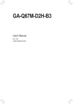
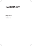
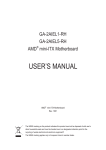
GA-6UASL series LGA1155 socket motherboard for Intel® Core™ i3 processors/ Intel® E3® series processors User's Manual Rev. 1001 Copyright © 2010 GIGA-BYTE TECHNOLOGY CO., LTD. All rights reserved. The trademarks mentioned in this manual are legally registered to their respective owners. Disclaimer Information in this manual is protected by copyright laws and is the property of GIGABYTE. Changes to the specifications and features in this manual may be made by GIGABYTE without prior notice. No part of this manual may be reproduced, copied, translated, transmitted, or published in any form or by any means without GIGABYTE's prior written permission. Documentation Classifications In order to assist in the use of this product, GIGABYTE provides the following types of documentations: For quick set-up of the product, read the Quick Installation Guide included with the product. For detailed product information, carefully read the User's Manual. For product-related information, check on our website at: http://www.gigabyte.com Table of Contents Box Contents....................................................................................................................4 GA-6UASL1 Motherboard Layout.....................................................................................5 Chapter 1 Hardware Installation......................................................................................7 1-1 1-2 Installation Precautions..................................................................................... 7 Product Specifications....................................................................................... 8 1-3-2 1-4 Installing the Memory...................................................................................... 12 1-4-1 1-4-2 1-5 1-6 1-7 Installing the CPU Cooler........................................................................................11 Dual Channel Memory Configuration......................................................................12 Installing a Memory ................................................................................................13 Back Panel Connectors................................................................................... 14 Internal Connectors......................................................................................... 16 Jumper Setting................................................................................................ 25 Chapter 2 BIOS Setup...................................................................................................29 2-1 2-2 The Main Menu............................................................................................... 31 Advanced Menu.............................................................................................. 33 2-2-1 2-2-2 2-2-3 2-2-4 2-2-5 2-2-6 2-2-7 2-2-8 2-2-9 2-2-10 2-2-11 2-3 2-4 2-4-1 2-4-2 2-5 2-6 2-7 Processor Configuration..........................................................................................34 Memory Configuration.............................................................................................38 Advanced Chipset Configuration.............................................................................39 ACPI Configuration..................................................................................................40 SATA Controller Configuration.................................................................................41 PCI Configuration....................................................................................................42 USB Configuration...................................................................................................44 Legacy Device Configuration...................................................................................45 Power Configuration................................................................................................46 Console Redirection................................................................................................47 Hardware Monitor....................................................................................................49 Security Menu................................................................................................. 50 Server Management Menu.............................................................................. 52 System Information......................................................................................... 53 Event Log Configuration.................................................................................. 54 Boot Option Menu........................................................................................... 56 Boot Manager.................................................................................................. 58 Exit Menu........................................................................................................ 59 -3- Box Contents GA-6UASL1 motherboard Driver CD Two SATA cables I/O Shield • The box contents above are for reference only and the actual items shall depend on the product package you obtain. The box contents are subject to change without notice. • The motherboard image is for reference only. -4- GA-6UASL1 Motherboard Layout -5- Item 1 2 3 4 5 6 7 8 9 10 11 12 13 14 15 16 17 18 19 20 21 22 23 24 25 27 28 29 30 31 32 33 34 35 36 37 Code PCI CASE_OPEN1 PCIE3 PCIE2 PCIE1 AUDIO1 (Optional) R_USB1 USB_LANA1 USB_LANB1 VGA1 COM1 FAN4 CPU1 VBoot_SEL P2_CPU1 NMI_BTN1 FAN1 PWR_DET1 DIMM1B DIMM1A DIMM2B DIMM2A BAT1 P1 ME_F_JP1 BIOS_JP1 CLR_CMOS1 SATA0~5 USB1 USB2 USB_A1 SGPIO1 HDD_LED1 F_PANEL2 TPM_1 COM2 Description PCI slot (32bit/33MHz) Case open intrusion connector PCI-E slot 3 (x4 slot) PCI-E slot 2 (x8 slot) PCI-E slot 1 (x16 slot) Audio jacks Rear USB connector USB connectors and LAN connector USB connectors VGA port Serial port System fan cable connector Intel LGA1155 socket Vcore voltage test jumper 8 pin power connector NMI button CPU fan cable connector Power management connector DIMM slot (channel B-1 ) DIMM slot (channel A-1 ) DIMM slot (channel B-2 ) DIMM slot (channel A-2 ) Battery socket 24 pin power connector ME recovery jumper BIOS recovery jumper Clear CMOS jumper SATA cable connectors USB connector USB connector Type A USB connector SGPIO connector HDD LED Front panel cable connector TPM connector Serial cable connector -6- Chapter 1 Hardware Installation 1-1 Installation Precautions The motherboard contains numerous delicate electronic circuits and components which can become damaged as a result of electrostatic discharge (ESD). Prior to installation, carefully read the user's manual and follow these procedures: • Prior to installation, do not remove or break motherboard S/N (Serial Number) sticker or warranty sticker provided by your dealer. These stickers are required for warranty validation. • Always remove the AC power by unplugging the power cord from the power outlet before installing or removing the motherboard or other hardware components. • When connecting hardware components to the internal connectors on the motherboard, make sure they are connected tightly and securely. • When handling the motherboard, avoid touching any metal leads or connectors. • It is best to wear an electrostatic discharge (ESD) wrist strap when handling electronic components such as a motherboard, CPU or memory. If you do not have an ESD wrist strap, keep your hands dry and first touch a metal object to eliminate static electricity. • Prior to installing the motherboard, please have it on top of an antistatic pad or within an electrostatic shielding container. • Before unplugging the power supply cable from the motherboard, make sure the power supply has been turned off. • Before turning on the power, make sure the power supply voltage has been set according to the local voltage standard. • Before using the product, please verify that all cables and power connectors of your hardware components are connected. • To prevent damage to the motherboard, do not allow screws to come in contact with the motherboard circuit or its components. • Make sure there are no leftover screws or metal components placed on the motherboard or within the computer casing. • Do not place the computer system on an uneven surface. • Do not place the computer system in a high-temperature environment. • Turning on the computer power during the installation process can lead to damage to system components as well as physical harm to the user. • If you are uncertain about any installation steps or have a problem related to the use of the product, please consult a certified computer technician. -7- Hardware Installation 1-2 Product Specifications CPU Support for Intel® Core™ i3 processors/Intel® Xeon® E3 series processors in the LGA1155 package L3 cache varies with CPU Chipset Intel® BD82C202 (Cougar Point) PCH Memory 4 x 1.5V DDR3 DIMM sockets supporting up to 32 GB of system memory Audio (optionl) LAN Expansion Slots *Due to Windows 32-bit operating system limitation, when more than 4 GB of physical memory is installed, the actual memory size displayed will be less than 4 GB. Dual channel memory architecture Support for DDR3 1333/1066 MHz memory modules Support for ECC memory modules Realtek ALC662 codec High Definition Audio 2/4/5.1-channel 1 x Intel® 82579LM supports 10/100/1000 Mbps 1 x Intel® 82574L supports 10/100/1000 Mbps (Optional/GA-6UASL2) 2 x Intel® 82574L supports 10/100/1000 Mbps (Optional/GA-6UASL3) 1 x PCI Express x16 slot, running at x16 (PCIE1) *For optimum performance, if only one PCI Express graphics card is to be installed, be sure to install it in the PCIEX16 slot. 1 x PCI Express x8 slot, running at x8 (PCIE2) 1 x PCI Express x4 slots (All PCI Express slots conform to PCI Express 2.0 standard.) 1 x PCI slot XGI Z9s supports 64MB VRAM Onboard Graphics Storage Interface 6 x SATA 3Gb/s connectors Support for Intel IRST SATA RAID 0, RAID 1, RAID 5, RAID 10 USB Up to 10 USB 2.0/1.1 ports (6 on the back panel, 3 via the USB brackets connected to the internal USB headers/GA-6UASL1) 1 x Type A USB connector Hardware Installation -8- Internal Connectors Back Panel Connectors 1 x 24-pin ATX main power connector 1 x 8-pin ATX 12V power connector 6 x SATA 3Gb/s connectors 1 x CPU fan header 1 x system fan header 1 x NMI switch 1 x front panel header 1 x audio header* 3 x USB 2.0/1.1 headers 1 x serial port header 6 x USB 2.0/1.1 ports (GA-6UASL1/2) 1 x RJ-45 port (GA-6UASL1) 2 x RJ-45 port (GA-6UASL2) 1 x COM port 1x VGA port 3 x audio jacks (Side Speaker Out/Line In/Line Out/Microphone)*Optional I/O Controller iTE IT8728 chip Hardware Monitor System voltage detection CPU/System temperature detection CPU/System/Power fan speed detection CPU overheating warning CPU/System/Power fan fail warning CPU/System fan speed control *Whether the CPU/system fan speed control function is supported will depend on the CPU/system cooler you install. BIOS 1 x 64 Mbit flash AMI BIOS Form Factor Micro ATX Form Factor; 9.6 inch x 9.6 inch * GIGABYTE reserves the right to make any changes to the product specifications and product-related information without prior notice. -9- Hardware Installation B. Follow the steps below to correctly install the CPU into the motherboard CPU socket. Before installing the CPU, make sure to turn off the computer and unplug the power cord from the power outlet power plug to prevent any damage to prevent damage to the CPU. Step 1: Gently press the CPU socket lever handle down and away from the socket with your finger. Then completely lift the CPU socket lever and the metal load plate will be lifted as well. Step 2: Remove the CPU socket cover as shown. Hold your index finger down on the rear grip of the socket cover and use your thumb to lift up the front edge (next to the "REMOVE" mark) and then remove the cover. (DO NOT touch socket contacts. To protect the CPU socket, always replace the protective socket cover when the CPU is not installed.) Step 3: Hold the CPU with your thumb and index fingers. Align the CPU pin one marking (triangle) with the pin one corner of the CPU socket (or you may align the CPU notches with the socket alignment keys) and gently insert the CPU into position. Step 4: Once the CPU is properly inserted, use one hand to hold the socket lever and use the other to lightly replace the load plate. When replacing the load plate, make sure the front end of the load plate is under the shoulder screw. Step 5: Push the CPU socket lever back into its locked position. NOTE: Hold the CPU socket lever by the handle, not the lever base portion. Hardware Installation - 10 - 1-3-2 Installing the CPU Cooler Follow the steps below to correctly install the CPU cooler on the motherboard. (The following procedure uses Intel® boxed cooler as the example cooler.) Male Push Pin Direction of the Arrow Sign on the Male Push Pin The Top of Female Push Pin Female Push Pin Step 1: Apply an even and thin layer of thermal paste on the surface of the installed CPU. Step 3: Place the cooler atop the CPU, aligning the four push pins through the pin holes on the motherboard. Push down on the push pins diagonally. Step 5: After the installation, check the back of the motherboard. If the push pin is inserted as the picture above shows, the installation is complete. Step 2: Before installing the cooler, note the direction of the arrow sign on the male push pin. (Turning the push pin along the direction of the arrow is for removing the cooler, and the opposite direction is for installing it..) Step 4: You should hear a "click" when pushing down each push pin. Check that the Male and Female push pins are joined closely. (Refer to your CPU cooler installation manual for instructions on installing the cooler.) Step 6: Finally, attach the power connector of the CPU cooler to the CPU fan header (CPU_FAN) on the motherboard. Use extreme care when removing the CPU cooler because the thermal grease/tape between the CPU cooler and CPU may adhere to the CPU. Inadequately removing the CPU cooler may damage the CPU. - 11 Hardware Installation 1-4 Installing the Memory Read the following guidelines before you begin to install the memory: • Make sure that the motherboard supports the memory. It is recommended that memory of the same capacity, brand, speed, and chips be used. (Go to GIGABYTE's website for the latest supported memory speeds and memory modules.) • Always turn off the computer and unplug the power cord from the power outlet before installing the memory to prevent hardware damage. • Memory modules have a foolproof design. A memory module can be installed in only one direction. If you are unable to insert the memory, switch the direction. 1-4-1 Dual Channel Memory Configuration This motherboard provides four DDR3 memory sockets and supports Dual Channel Technology. After the memory is installed, the BIOS will automatically detect the specifications and capacity of the memory. Enabling Dual Channel memory mode will double the original memory bandwidth. The four DDR3 memory sockets are divided into two channels and each channel has two memory sockets as following: Channel A: DIMM1A, DIMM2A Channel B: DIMM1B, DIMM2B DIMM1B DIMM1A DIMM2B DIMM2A Due to CPU limitations, read the following guidelines before installing the memory in Dual Channel mode. 1. Dual Channel mode cannot be enabled if only one DDR3 memory module is installed. 2. When enabling Dual Channel mode with two or four memory modules, it is recommended that memory of the same capacity, brand, speed, and chips be used for optimum performance. Hardware Installation - 12 - 1-4-2 Installing a Memory Before installing a memory module, make sure to turn off the computer and unplug the power cord from the power outlet to prevent damage to the memory module. Be sure to install DDR3 DIMMs on this motherboard. Installation Step: Step 1. Insert the DIMM memory module vertically into the DIMM slot, and push it down. Step 2. Close the plastic clip at both edges of the DIMM slots to lock the DIMM module. NOTE! DIMM must be populated in order starting from DIMM1A socket. For dual-channel operation, DIMMs must be installed in matched pairs. Step 3. Reverse the installation steps when you wish to remove the DIMM module. 2 1 2 - 13 - Hardware Installation 1-5 Back Panel Connectors GA-6UASL1 GA-6UASL2 GA-6UASL3 Serial Port Connects to serial-based mouse or data processing devices. Video Port The video in port allows connect to video in, which can also apply to video loop thru function. USB 2.0/1.1 Port The USB port supports the USB 2.0/1.1 specification. Use this port for USB devices such as a USB keyboard/mouse, USB printer, USB flash drive and etc. RJ-45 LAN Port The Gigabit Ethernet LAN port provides Internet connection at up to 1 Gbps data rate. The following describes the states of the LAN port LEDs. Line In Jack (Blue) The default line in jack. Use this audio jack for line in devices such as an optical drive, walkman, etc. Line Out Jack (Green) The default line out jack. Use this audio jack for a headphone or 2-channel speaker. This jack can be used to connect front speakers in a 4/5.1/7.1-channel audio configuration. Mic In Jack (Pink) The default line out jack. Use this audio jack for a headphone or 2-channel speaker. This jack can be used to connect front speakers in a 4/5.1/7.1-channel audio configuration. - 14 - Hardware Installation Connection/ Speed LED Activity LED LAN Port Connection/Speed LED: State Orange Green Off Activity LED: Description 1 Gbps data rate 100 Mbps data rate 10 Mbps data rate State Description Blinking Data transmission or receiving is occurring Off No data transmission or receiving is occurring • When removing the cable connected to a back panel connector, first remove the cable from your device and then remove it from the motherboard. • When removing the cable, pull it straight out from the connector. Do not rock it side to side to prevent an electrical short inside the cable connector. Hardware Installation - 15 - 1-6 Internal Connectors 1) 2) 3) 4) 5) 6) 7) 8) P1 P2_CPU1 CASE_OPEN1 PWR_DET1 FAN4 (System Fan) FAN1 (CPU Fan) BAT1 SATA0/1/2/3/4/5 9) 10) 11) 12) 13) 14) 15) 16) USB1 USB2 USB_A1 SGPIO1 HD_LED1 F_PANEL2 TPM_1 COM2 Read the following guidelines before connecting external devices: • First make sure your devices are compliant with the connectors you wish to connect. • Before installing the devices, be sure to turn off the devices and your computer. Unplug the power cord from the power outlet to prevent damage to the devices. • After installing the device and before turning on the computer, make sure the device cable has been securely attached to the connector on the motherboard. - 16 - Hardware Installation 1/2)P1/P2_CPU1 (2x4 12V Power Connector and 2x12 Main Power Connector) With the use of the power connector, the power supply can supply enough stable power to all the components on the motherboard. Before connecting the power connector, first make sure the power supply is turned off and all devices are properly installed. The power connector possesses a foolproof design. Connect the power supply cable to the power connector in the correct orientation. The 12V power connector mainly supplies power to the CPU. If the 12V power connector is not connected, the computer will not start. To meet expansion requirements, it is recommended that a power supply that can withstand high power consumption be used (500W or greater). If a power supply is used that does not provide the required power, the result can lead to an unstable or unbootable system. ATX_12V_2X4: 4 8 1 5 P2_CPU1 1 P1 Pin No. 1 2 3 4 5 6 7 8 Definition GND (Only for 2x4-pin 12V) GND (Only for 2x4-pin 12V) GND GND +12V (Only for 2x4-pin 12V) +12V (Only for 2x4-pin 12V) +12V +12V 12 13 24 P1: Pin No. 1 2 3 4 5 6 7 8 9 10 11 12 Hardware Installation Definition 3.3V 3.3V GND +5V GND +5V GND Power Good 5VSB (stand by +5V) +12V +12V (Only for 2x12-pin ATX) 3.3V (Only for 2x12-pin ATX) Pin No. 13 14 15 16 17 18 19 20 21 22 23 24 - 17 - Definition 3.3V -12V GND PS_ON (soft On/Off) GND GND GND -5V +5V +5V +5V (Only for 2x12-pin ATX) GND (Only for 2x12-pin ATX) CLR_CMOS BIOS_WP 3) CASE_OPEN1 (Case Open Intrusion) CLR_CMOS BIOS_WP SUR_CEN 1 Pin No. Definition 1 Case Open 2 GND CI 2 CLR_PWD MODEM DPVRM F1_1394 SPDIF_IO 4) PWR_DET1 (Power management connector) 1 GAME 5 - 18 - Pin No. 1 2 3 6 7 Definition SMB CLK SMB DATA SMB Alert GND 3.3V Sense SMB_CONN Hardware Installation 5/6) FAN1/FAN4 (CPU Fan/System Fan Headers) The motherboard has a 4-pin CPU fan header (FAN1), a 4-pin (FAN4) system fan headers. Most fan headers possess a foolproof insertion design. When connecting a fan cable, be sure to connect it in the correct orientation (the black connector wire is the ground wire). The motherboard supports CPU fan speed control, which requires the use of a CPU fan with fan speed control design. For optimum heat dissipation, it is recommended that a system fan be installed inside the chassis. FAN1 (CPU Fan): Pin No. 1 2 3 4 FAN1 1 FAN4 Definition GND +12V / Speed Control Sense Speed Control FAN4 (System Fan): Pin No. 1 2 3 4 Definition GND +12V / Speed Control Sense Reserve • Be sure to connect fan cables to the fan headers to prevent your CPU and system from overheating. Overheating may result in damage to the CPU or the system may hang. • These fan headers are not configuration jumper blocks. Do not place a jumper cap on the headers. 7) BAT (Battery) The battery provides power to keep the values (such as BIOS configurations, date, and time information) in the CMOS when the computer is turned off. Replace the battery when the battery voltage drops to a low level, or the CMOS values may not be accurate or may be lost. You may clear the CMOS values by removing the battery: 1. Turn off your computer and unplug the power cord. 2. Gently remove the battery from the battery holder and wait for one minute. (Or use a metal object like a screwdriver to touch the positive and negative terminals of the battery holder, making them short for 5 seconds.) 3. Replace the battery. 4. Plug in the power cord and restart your computer. • Always turn off your computer and unplug the power cord before replacing the battery. • Replace the battery with an equivalent one. Danger of explosion if the battery is replaced with an incorrect model. • Contact the place of purchase or local dealer if you are not able to replace the battery by yourself or uncertain about the battery model. • When installing the battery, note the orientation of the positive side (+) and the negative side (-) of the battery (the positive side should face up). • Used batteries must be handled in accordance with local environmental regulations. - 19 - Hardware Installation PORT PORT PORT 8) SATA0/1/2/3/4/5 (SATA 3Gb/s Connectors) 7 Pin No. 1 2 3 4 5 6 7 SATA0 SATA2 1 SATA3 The SATA connectors conform to SATA 3Gb/s standard and are compatible with SATA 1.5Gb/s standard. Each SATA connector supports a single SATA device. SATA4 SATA5 SATA0 G.QBOFM Definition GND TXP TXN GND RXN RXP GND • A RAID 0 or RAID 1 configuration requires at least two hard drives. If more than two hard drives are configured, the total number of hard drives must be an even number. • A RAID 5 configuration requires at least three hard drives. (The total number of hard drives does not have to be an even number.) • A RAID 10 configuration requires four hard drives. (Note) When a RAID configuration is built across the SATA 3Gb/s channels, the system performance of the RAID configuration may vary depends on the devices are connected. 9) USB1 (USB Headers) The headers conform to USB 2.0/1.1 specification. Each USB header can provide two USB ports via an optional USB bracket. For purchasing the optional USB bracket, please contact the local dealer. 10 9 2 1 Pin No. 1 2 3 4 5 6 7 8 9 10 Definition Power (5V) Power (5V) USB DXUSB DYUSB DX+ USB DY+ GND GND No Pin OC When the system is in S4/S5 mode, only the USB ports routed to the F_USB1 header can support the ON/OFF Charge function. Hardware Installation - 20 - 10) USB2 (USB Headers) The headers conform to USB 2.0/1.1 specification. Pin No. 1 2 3 4 5 Definition Power (5V) USB DYUSB DY+ GND OC When the system is in S4/S5 mode, only the USB ports routed to the F_USB1 header can support the ON/OFF Charge function. 11) USB_A1 (Type A USB Headers) - 21 - Hardware Installation F_PANEL 12) SGPIO1 (SGPIO Header) SGPIO is stands for Serial General Purpose Input/Output which is a 4-signal (or 4-wire) bus used between a Host Bus Adapter (HBA) and a backplane. Out of the 4 signals, 3 are driven IR/CIRby the HBA and 1 is driven by the backplane. Typically, the HBA is a storage controller located inside a server, desktop, rack or workstation computer that interfaces with Hard disk drives (HDDs) to store and retrieve data. F_PANEL 1 4 PWR_LED Pin No. 1 2 3 4 Definition IR Clock Load Data 0 Data 1 F_USB CLR_CMOS BIOS_WP 13)HD_LED1 CLR_CMOS BIOS_WP SUR_CEN 1 CI 2 Pin No. Definition 1 LED Active 2 NC CLR_PWD MODEM DPVRM F1_1394 SPDIF_IO - 22 - Hardware Installation 14) F_PANEL2 (Front Panel Header) Connect the power switch, reset switch, speaker, chassis intrusion switch/sensor and system status indicator on the chassis to this header according to the pin assignments below. Note the positive and negative pins before connecting the cables. 1 2 17 18 Pin No. 1 2 3 4 5 6 7 8 9 10 11 12 13 14 15 16 17 18 Signal Name HD+ PWR+ HD- PWR- NA SW+ NA GND NA NA NA NA NA NA LAN- PWR+ LAN+ NA Definition Hard Disk LED Signal anode (+) Power LED + Hard Disk LED Signal cathode(-) Power LED Signal cathode(-) No Connect Power Button No Connect Ground No Connect No Connect No Connect No Connect No Connect No Connect LAN active LED Signal cathode(-) Power LED Signal anode (+) LAN active LED Signal anode (+) No Connect The front panel design may differ by chassis. A front panel module mainly consists of power switch, reset switch, power LED, hard drive activity LED, speaker and etc. When connecting your chassis front panel module to this header, make sure the wire assignments and the pin assignments are matched correctly. - 23 - Hardware Installation 15) TPM1 (TPM Module Header) Trusted Platform Module(TPM) Platform provides function forsecure generation of cryptographic keys, the ability to limit the use of cryptographic keys, aswell as a hardware pseudo-random number generator. To enable TPM function, you must connect a TPM module and configre advanced setting in BIOS Setup Menu in Chapter 2 BIOS Setup. 1 2 19 20 Pin No. 1 2 3 4 5 6 7 8 9 10 Definition 33MHz Clock GND LFRAME# NC TPM Rest NC LAD3 TPM Disable 3.3V LAD 1 Pin No. 11 11 13 14 15 16 17 18 19 20 Definition LAD 0 GND NC NC 3.3V AUX Serial IRQ GND Clock Run LPCPD NC 16) COM2 (Serial Port Header) The COM header can provide one serial port via an optional COM port cable. For purchasing the optional COM port cable, please contact the local dealer. Hardware Installation 1 2 9 10 - 24 - Pin No. 1 2 3 4 5 6 7 8 9 10 Definition NDCDNSIN NSOUT NDTRGND NDSRNRTSNCTSNRINo Pin 1-7 Jumper Setting 1) 2) 3) 4) 5) VBoot_SEL BIOS_JP1 ME_F_JP1 PWD_JP1 CLR_CMOS1 - 25 - Hardware Installation 1) VBoot_SEL (Core Voltage Test Jumper) 1 1-2 Close: Factory test. 1 2-3 Close: Intel default. (Default setting) 2) BIOS_JP1 (BIOS Recovery Jumper) 1 1-2 Close: Normal operation. (Default setting) 1 2-3 Close: BIOS recovery mode. - 26 - Hardware Installation 3) MFG_F_JP1 (ME Recovery Jumper) 1 1-2 Close: Enable ME recovery. (Default setting) 1 2-3 Close: Disable ME recovery. 4) PWD_JP1 (Clear Password Jumper) Use this jumper to clear the supervisor password. 1 1-2 Close: Normal operation (Default setting) 1 2-3 Close: Clear password. - 27 - Hardware Installation 5) CLR_CMOS1 (Clearing CMOS Jumper) Use this jumper to clear the CMOS values (e.g. date information and BIOS configurations) and reset the CMOS values to factory defaults. To clear the CMOS values, place a jumper cap on the two pins to temporarily short the two pins or use a metal object like a screwdriver to touch the two pins for a few seconds. 1 1-2 Close: Normal operation (Default setting) 1 2-3 Close: Clear CMOS data • Always turn off your computer and unplug the power cord from the power outlet before clearing the CMOS values. • After clearing the CMOS values and before turning on your computer, be sure to remove the jumper cap from the jumper. Failure to do so may cause damage to the motherboard. • After system restart, go to BIOS Setup to load factory defaults (select Load Optimized Defaults) or manually configure the BIOS settings (refer to Chapter 2, "BIOS Setup," for BIOS configurations). Hardware Installation - 28 - Chapter 2 BIOS Setup BIOS (Basic Input and Output System) records hardware parameters of the system in the CMOS on the motherboard. Its major functions include conducting the Power-On Self-Test (POST) during system startup, saving system parameters and loading operating system, etc. BIOS includes a BIOS Setup program that allows the user to modify basic system configuration settings or to activate certain system features. When the power is turned off, the battery on the motherboard supplies the necessary power to the CMOS to keep the configuration values in the CMOS. To access the BIOS Setup program, press the <F2> key during the POST when the power is turned on. To see more advanced BIOS Setup menu options, you can press <Ctrl> + <F1> in the main menu of the BIOS Setup program. • BIOS flashing is potentially risky, if you do not encounter problems of using the current BIOS version, it is recommended that you don't flash the BIOS. To flash the BIOS, do it with caution. Inadequate BIOS flashing may result in system malfunction. • It is recommended that you not alter the default settings (unless you need to) to prevent system instability or other unexpected results. Inadequately altering the settings may result in system's failure to boot. If this occurs, try to clear the CMOS values and reset the board to default values. (Refer to the "Load Optimized Defaults" section in this chapter or introductions of the battery/ clearing CMOS jumper in Chapter 1 for how to clear the CMOS values.) BIOS Setup Program Function Keys <h><i><f><g>Move the selection bar to select an item <Enter> Execute command or enter the submenu <Esc> Main Menu: Exit the BIOS Setup program Submenus: Exit current submenu <Page Up> Increase the numeric value or make changes <Page Down> Decrease the numeric value or make changes <F1> Show descriptions of the function keys <F2> Move cursor to the Item Help block on the right (submenus only) <F5> Restore the previous BIOS settings for the current submenus <F6> Load the Fail-Safe BIOS default settings for the current submenus <F7> Load the Optimized BIOS default settings for the current submenus <F8> Access the Q-Flash utility <F9>Display system information <F10> Save all the changes and exit the BIOS Setup program <F11> Save CMOS to BIOS <F12> Load CMOS from BIOS - 29 - BIOS Setup The Functions of the <F11> and <F12> keys (For the Main Menu Only) F11: Save CMOS to BIOS This function allows you to save the current BIOS settings to a profile. You can create up to 8 profiles (Profile 1-8) and name each profile. First enter the profile name (to erase the default profile name, use the SPACE key) and then press <Enter> to complete. F12: Load CMOS from BIOS If your system becomes unstable and you have loaded the BIOS default settings, you can use this function to load the BIOS settings from a profile created before, without the hassles of reconfiguring the BIOS settings. First select the profile you wish to load, then press <Enter> to complete. Advanced This setup page includes all the items of AMI BIOS special enhanced features. (ex: Auto detect fan and temperature status, automatically configure hard disk parameters.) Security Change, set, or disable supervisor and user password. Configuration supervisor password allows you to restrict access to the system and BIOS Setup. A supervisor password allows you to make changes in BIOS Setup. A user password only allows you to view the BIOS settings but not to make changes. Server additional features enabled/disabled setup menus. This setup page provides items for configuration of boot sequence. This setup page provides configuration of boot up devices. Server Management Boot Options Boot Manager Exit Save all the changes made in the BIOS Setup program to the CMOS and exit BIOS Setup. (Pressing <F10> can also carry out this task.) Abandon all changes and the previous settings remain in effect. Pressing <Y> to the confirmation message will exit BIOS Setup. (Pressing <Esc> can also carry out this task.) - 30 - BIOS Setup 2-1 The Main Menu Once you enter the BIOS Setup program, the Main Menu (as shown below) appears on the screen. Use arrow keys to move among the items and press <Enter> to accept or enter other sub-menu. Main Menu Help The on-screen description of a highlighted setup option is displayed on the bottom line of the Main Menu. Submenu Help While in a submenu, press <F1> to display a help screen (General Help) of function keys available for the menu. Press <Esc> to exit the help screen. Help for each item is in the Item Help block on the right side of the submenu. • If you do not find the settings you want in the Main Menu or a submenu, press <Ctrl>+<F1> to access more advanced options. • When the system is not stable as usual, select the Load Optimized Defaults item to set your system to its defaults. • The BIOS Setup menus described in this chapter are for reference only and may differ by BIOS version. - 31 - BIOS Setup BIOS Version Display version number of the BIOS setup utility. BIOS Build Date Displays the date when the BIOS setup utility was created. Processor Information: CPU Type / CPU Core Frequency / CPU Count Displays the technical specifications for the installed processor. Memory Determines how much total memory is present during the POST. System Date Set the date following the weekday-month-day- year format. System Time Set the system time following the hour-minute- second format. BIOS Setup - 32 - 2-2 Advanced Menu The Advanced menu display submenu options for configuring the function of various hardware components. Select a submenu item, then press Enter to access the related submenu screen. - 33 - BIOS Setup 2-2-1 Processor Configuration BIOS Setup - 34 - Intel Hyper Threading Technology The Intel Hyper Threading Technology allows a single processor to execute two or more separate threads concurrently. When hyper-threading is enabled, multi-threaded software applications can execute their threads, thereby improving performance. Options available: Enabled/Disabled. Default setting is Enabled. Active Processor Cores (Note) Allows you to determine whether to enable all CPU cores. Options available: All/1/2/3. Default setting is All. Execute Disable Bit Capability When this item enabled, the processor prevents the execution of code in data-only memory pages. This provides some protection against buffer overflow attacks. Options available: Enabled/Disabled. Default setting is Enabled. Intel Virtualization Technology Select whether to enable the Intel Virtualization Technology function. VT allows a single platform to run multiple operating systems in independent partitions. Options available: Enabled/Disabled. Default setting is Disabled. Intel AES-NI Support (Intel Advanced Encryption Standard Instructions) Intel Advanced Encryption Standard Instructions (AES-NI), is a symmetric block cipher that encrypts/ decrypts data through several rounds. AES-NI can be used to accelerate the performance of an implementation of AES by 3 to 10x over a completely software implementation. Options avaiable: Enabled/Disabled. Default setting is Disabled. Intel EIST Support (Enhanced Intel SpeedStep Technology) Conventional Intel SpeedStep Technology switches both voltage and frequency in tandem between high and low levels in response to processor load. Options available: Enabled/Disabled. Default setting is Enabled. - 35 - BIOS Setup P-State Coordination In HW_ALL mode, the processor hardware is responsible for coordinating the P-state among logical processors dependencies. The OS is responsible for keeping the P-state request up to date on all logical processors. In SW_ALL mode, the OS Power Manager is responsible for coordinating the P-state among logical processors with dependencies and must initiate the transition on all of those Logical Processors. In SW_ANY mode, the OS Power Manager is responsible for coordinating the P-state among logical processors with dependencies and may initiate the transition on any of those Logical Processors. Options available: HW_ALL/SW_ALL/SW_ANY. Default setting is HW_ALL. Intel Turbo Boost Technology When this feature is enabled, the processor can dynamically overclock one or two of its four processing cores to improve performance with applications that are not multi-threaded or optimized for quad-core processors. Options available: Enabled/Disabled. Default setting is Enabled. C1E Support (CPU Enhanced Halt) (Note) Enables or disables Intel CPU Enhanced Halt (C1E) function, a CPU power-saving function in system halt state. When enabled, the CPU core frequency and voltage will be reduced during system halt state to decrease power consumption. Options available: Enabled/Disabled. Default setting is Enabled. CPU C3/C6 Support (Note) Allows you to determine whether to let the CPU enter C3/C6 mode in system halt state. When enabled, the CPU core frequency and voltage will be reduced during system halt state to decrease power consumption. The C3/C6 state is a more enhanced power-saving state than C1. Auto lets the BIOS automatically configure this setting. Options available for CPU C3 Report: ACPI C2/ACPI C3/Disabled. Default setting is ACPI C2. Options available for CPU C6 Report: Enabled/Disabled. Default setting is Enabled. Package C State Limit Configure state for the C-State package limit. Options available: C0/C1/C6/C7/No Limit. Default setting is No Limit. Hardware Prefetcher Select whether to enable the speculative prefetch unit of the processor. Options available: Enabled/Disabled. Default setting is Enabled. Adjacent Cache Line Prefetch When enabled, cache lines are fetched in pairs. When disabled, only the required cache line is fetched. Options available: Enabled/Disabled. Default setting is Enabled. CPU Speed The processor speed is the speed at which a microprocessor executes instructions. Clock speeds are expressed in megahertz (MHz), with 1 MHz being equal to 1 million cycles per second. The faster the clock, the more instructions the CPU can execute per second. EMT64 Displays Processor EMT64 support status (Note) This item is present only if you install a CPU that supports this feature. For more information about Intel CPUs' unique features, please visit Intel's website. - 36 - BIOS Setup Core Count Displays Processor core count information. CPU Stepping Display processor stepping information. Microcode Revision Display Microcode Revision. Intel HT Technology Display Intel Hyper Threading Technology function support information. BIOS Setup - 37 - 2-2-2 Memory Configuration Available Memory Total size of system memory detected during POST. Memory Type Display information of installed memory type. Memory Reset Select whether to delete the historical memory data log. System memory will be retested on the next boot-up. Options available: Yes/No. Default setting is No. DIMM Group #1/2/3/4 Status The size of memory installed on each of the DDR3 slots. - 38 - BIOS Setup 2-2-3 Advanced Chipset Configuration Intel VD-d Technology Enable/Disable Intel VD-d Technology function. Options available: Enabled/Disabled. Default setting is Disabled. Intel TXT Technology Enable/Disable Intel TXT Technology function. Options available: Enabled/Disabled. Default setting is Disabled. - 39 - BIOS Setup 2-2-4 ACPI Configuration HPET Support (High Precision Event Timer) Enable/Disable HPET Support. Options available: Enabled/Disabled. Default setting is Enabled. WHEA Support (Windows Hardware Error Architecture) Enable/Disable WHEA Support. Options available: Enabled/Disabled. Default setting is Enabled. - 40 - BIOS Setup 2-2-5 SATA Controller Configuration SATA Controller When enabled, the SATA controller will function normally. Options available: Enabled/Disabled. Default setting is Enabled. SATA Mode Select the on chip SATA type. IDE Mode: When set to IDE, the SATA controller disables its RAID and AHCI functions and runs in the IDE emulation mode. This is not allowed to access RAID setup utility. RAID Mode: When set to RAID, the SATA controllerenables both its RAID and AHCI functions. You will be allows access the RAID setup utility at boot time. ACHI Mode: When set to AHCI,the SATA controller enables its AHCI functionality. Then the RAID function is disabled and cannot be access the RAID setup utility at boot time. Options available: IDE/RAID/ACHI. Default setting is ACHI Mode. SATA Port 0/1/2/3/4/5 Displays the installed HDD devices. BIOS Setup - 41 - 2-2-6 PCI Configuration PERR# Generation When this item is set to enabled, PCI bus system error (SERR) is generated and is routed to NMI. Options available: Enabled/Disabled. Default setting is Enabled. SERR# Generation When this item is set to enabled, PCI bus parity error (PERR) is generated and is routed to NMI. Options available: Enabled/Disabled. Default setting is Enabled. PCI Express Slot 1/2/3/4 I/O ROM When enabled, This setting will initialize the device expansion ROM for the related PCI-E slot. Options available: Enabled/Disabled. Default setting is Enabled. BIOS Setup - 42 - Onboard Graphics Controller When enabled, the graphic controller will function normally. Options available: enabled/Disabled. Default setting is Enabled. Primary Graphics Select the primary video device that that the BIOS will use for output. Options available: Add-On/Onboard. Default setting is Add-On. Onboard LAN1 Controller When enabled, the system will enable the onboard LAN devices. Options available: enabled/Disabled. Default setting is Enabled. Onboard LAN1 I/O ROM Select whether to enable the selected onboard LAN device. When enabled, device expansion ROM will be initialized. Options available: enabled/Disabled. Default setting is Disabled. Onboard LAN1 I/O ROM Option Select whether to enable the selected onboard LAN device. When enabled, device expansion ROM will be initialized. Options available: PXE/iSCSI. Default setting is PXE. PCI ROM Priority In case of multiple Option ROMs (Legacy and EFI Compatible) specifies what PCI option ROM to launch. Options available: Legacy ROM/EFI Compatible ROM. Default setting is EFI Compatible ROM. - 43 - BIOS Setup 2-2-7 USB Configuration Detected USB Devices Displays the information of installed USB devices in the system. USB Controller When enabled, the USB controller will function normally. Options available: Enabled/Disabled. Default setting is Enabled. Legacy USB Support Enables or disables support for legacy USB devices. Options available: Enabled/Disabled. Default setting is Enabled. Port 60/64 Emulation Enable I/O port 60h/64h emulation support. This should be enabled for the complete USB Keyboard Legacy support for non-USB aware OS. Options available: Enabled/Disabled. Default setting is Disabled. Mass Storage Reset Timeout Define USB Mass Storage Device Start Unit command timeout. Options available: 10 sec/20sec/30sec/40sec. BIOS Setup - 44 - 2-2-8 Legacy Device Configuration Serial Port 1/2 When enabled allows you to configure the serial port settings. When set to Disabled, displays no configuration for the serial port. Options available: Enabled/Disabled. Default setting is Enabled. Device Settings Displays Serial Port 1/2 device setting information. Change Settings Change Serial Port 1/2 device settings. When set to Auto allows the server’s BIOS or OS to select a configuration. Options available: Auto/IO=3F8; IRQ=4/IO=3F8h; IRQ=3,4,5,6,7,10,11,12/ IO=2F8h; IRQ=3,4,5,6,7,10,11,12 /IO=3E8h; IRQ=3,4,5,6,7,10,11,12/IO=2E8h; IRQ=3,4,5,6,7,10,11,12. BIOS Setup - 45 - 2-2-9 Power Configuration Deep Power Off Mode Enable or Disable Deep Power Off Mode. Options available: Enabled/Disabled. Default setting is Enabled. Power On by RTC Alarm Select whether to wake up the system when an RTC alarm is detected. Options available: Enabled/Disabled. Default setting is Disabled. Restore on AC Power Loss Defines the power state to resume to after a sys- tem shutdown that is due to an interruption in AC power. When set to Last State, the system will return to the active power state prior to shutdown. When set to Stay Off, the system remains off after power shutdown. Options available: Last State/Stay Off/Power On. Default setting is Last State. BIOS Setup - 46 - 2-2-10 Console Redirection Console Redirection (Note) Select whether to enable console redirection. Console redirection enables users to manage the system from a remote location. Options available: Serial Port1/Serial Port2/Disabled. Default setting is Disabled. Terminal Type Select a terminal type to be used for console redirection. Options available: VT100/VT100+/ANSI /VT-UTF8. Bits per second Select the baud rate for console redirection. Options available: 9600/19200/57600/115200. Parity A parity bit can be sent with the data bits to detect some transmission errors. Even: parity bi is 0 if the num of 1's in the data bits is even. Odd: parity bit is0if num of 1's the data bits is odd. Mark: parity bit is always 1. Space: Parity bit is always 0. Mark and Space Parity do not allow for error detection. Options available: None/Even/Odd/Mark/Space. Stop Bits Stop bits indicate the end of a serial data packet. (A start bit indicates the beginning). The standard setting is 1 stop bit. Communication with slow devices may require more than 1 stop bit. Options available: 1/2. Flow Control Flow control can prevent data loss from buffer overflow. When sending data, if the receiving buffers are full, a 'stop' signal can be sent to stop the data flow. Once the buffers are empty, a 'start' signal can be sent to re-start the flow. Hardware flow control uses two wires to send start/stop signals. Options available: None/Hardware RTS/CTS. (Note) Advanced items prompt when this item is defined. BIOS Setup - 47 - Recorder Mode When this mode enabled, only text will be send. This is to capture Terminal data. Options available: Enabled/Disabled. Resolution 100x31 Enables or disables extended terminal resolution. Options available: Enabled/Disabled. Legacy OS Redirection Resolution On Legacy OS, the number of Rows and Columns supported redirection. Options available: 80x24/80X25. BIOS Setup - 48 - 2-2-11 Hardware Monitor Press Enter to view the Hardware Monitor screen which displays a real-time record of the CPU/system temperature, fan speed, and voltage. Items on this window are non-configurable. Current CPU/Slot/FP Temperature Displays current bus CPU/Slot/FP temperature. Current FAN 1/2/3 Speed (RPM) Displays current CPU/system fan speed. Current Voltage(V) P_VCC_CPU/P_1V5_VDDQ/P12V/P5V/P3V3/P1V8/P1V05_PCH/VBAT Displays the current CPU and system voltages. BIOS Setup - 49 - 2-3 Security Menu The Security menu allows you to safeguard and protect the system from unauthorized use by setting up access passwords. There are two types of passwords that you can set: • Administrator Password Entering this password will allow the user to access and change all settings in the Setup Utility. • User Password Entering this password will restrict a user’s access to the Setup menus. To enable or disable this field, a Administrator Password must first be set. A user can only access and modify the System Time, System Date, and Set User Password fields. Administrator Password Status This parameter indicates whether a Administrator Password has been assigned. User Password Status This parameter indicates whether a user pass- word has been assigned. To clear the password, press <Enter> on the password item and when requested for the password, press <Enter> again. The message "PASSWORD DISABLED" will appear, indicating the password has been cancelled. Set Administrator Password Press Enter to configure the Administrator password. Set User Password Press Enter to configure the user password. Power/Reset Button Lockout Enable or disable Power Button Lockout. Options available: Enabled/Disabled. Default setting is Disabled. Power/Reset Button Lockout Enable or disable Power Button Lockout. Options available: Enabled/Disabled. Default setting is Disabled. TPM Support Select Enabled to activate TPM support feature. - 50 - BIOS Setup Options available: Enabled/Disabled. Default setting is Enabled. TPM State Select Enabled to activate TPM State function. Options available: Enabled/Disabled. Default setting is Enabled. Pending TPM Support Schedule TPM operation. Options available: None/Enable Take Ownership. Current TPM Status Information Display current TPM status information. Setting a System Password 1. U se the up/down keys to select a password parameter (Set Administrator Password or Set User Password), then press Enter. A password box will appear. 2. Type a password then press Enter. 3. The password may consist of up to eight alphanumeric characters (A-Z, a-z, 0-9). 4. Retype the password to verify the first entry then press Enter again. 5. Press F10. 5. Select Yes to save the new password and close the Setup Utility. Changing a System Password 1. U se the up/down keys to select a password parameter (Set Administrator Password or Set User Password), then press Enter. 2. Type the original password then press Enter. 3. Type a new password then press Enter. 4. Retype the password to verify the first entry then press Enter again. 5. Press F10. 6. Select Yes to save the modified password and close the Setup Utility. Removing a System Password 1. Use the up/down keys to select a password parameter (Set Administrator Password of Set User Password), then press Enter. 2. Enter the current password then press Enter. 3. Press Enter twice without entering anything in the new and confirm password fields. After doing this, the system automatically sets the related password parameter to Clear. - 51 - BIOS Setup 2-4 Server Management Menu System Information Displays basic system ID information, as well as BIOS version. Press Enter to access the related submenu. Event Log Configuration Displays Event Log advanced settings. Press Enter to access the related submenu. - 52 - BIOS Setup 2-4-1 System Information The System Management submenu is a simple display page for basic system ID information, as well as System product information. Items on this window are non-configurable. - 53 - BIOS Setup 2-4-2 Event Log Configuration - 54 - BIOS Setup Change SMBIOS Event Settings Press Enter to access the related submenu. View Smbios Event Log Displays Smbios Event Log . Press Enter to View Smbios Event Log. Erase Event Log Choose options for erasing Smbios Event Log Erasing is done prior to any logging activation during reset. Options available: No/Yes, next reset/Yes, every reset. When Log is Full Choose options for reactions to a full Smbios Event Log. Options available: Do Nothing/Erase immediately. Multi Event Count Increment Displays information of Multi Event Count Increment. Log OEM Codes Enable or Disable the logging of EFI Status Codes as OEM Codes. Options available: Enabled/Disabled. Convert OEM Codes Enable or disable the converting of EFI Status Codes to Standard Smbios Types. Options available: Enabled/Disabled. • All values changed here do not take action until computer is restarted. - 55 - BIOS Setup 2-5 Boot Option Menu The Boot menu allows you to set the drive priority during system boot-up. BIOS setup will display an error message if the drive(s) specified is not bootable. By default, the server searches for boot devices in the following order: 1. Hard drive. 2. UEFI device. 3. Optical disc drive. 4. Removable device. UEFI Boot Device Priority Press Enter to configure the boot priority. Hard Disk Drive Priority Press Enter to configure the boot priority. Optical Disk Drive Priority Press Enter to configure the boot priority. Removable Disk Drive Priority Press Enter to configure the boot priority. Network Device Priority Press Enter to configure the boot priority. Quiet Boot Enables or disables the quick boot function to speed up the system boot-up process to shorten the waiting time for entering the operating system and to deliver greater efficiency for daily use. Options available: Enabled/Disabled. Default setting is Enabled. Bootup NumLock Enable or Disable Bootup NumLock function. Options available: On/Off. Default setting is On. POST Error Pause Select whether to pause POST when a boot-up error is detected. Options available: Enabled/Disabled. Default setting is Enabled. - 56 - BIOS Setup POST Error Pause Select whether to pause POST when a boot-up error is detected. Options available: Enabled/Disabled. Default setting is Enabled. Option ROM Messages Set display mode for Option ROM. Options available: Force BIOS/Keep Current . Default setting is Force BIOS. BIOS Watch Timer Enable/Disable BIOS Watch Timing function. Options available: Enabled/Disabled. Default setting is Disabled. - 57 - BIOS Setup 2-6 Boot Manager The Boot manager menu allows you to specify the boot-up drive. BIOS setup will display an error message if the drive(s) specified is not bootable. Built-in EFI Shell Press Enter to configure the device as the boot-up drive. P3: WDC WD1001FAES-22W7A0 Press Enter to configure the device as the boot-up drive. P5: ATAPI DVD D DH16D5SH Press Enter to configure the device as the boot-up drive. - 58 - BIOS Setup 2-7 Exit Menu The Exit menu displays the various options to quit from the BIOS setup. Highlight any of the exit options then press Enter. Save Changes and Exit Saves changes made and close the BIOS setup. Options available: Yes/No. Discard Changes and Exit Discards changes made and close the BIOS setup. Options available: Yes/No. Save Changes Saves changes made in the BIOS setup. Options available: Yes/No. Discard Changes Discards all changes made in the BIOS setup. Options available: Yes/No. Load Default Values Loads the default settings for all BIOS setup parameters. Setup Defaults are quite demanding in terms of resources consumption. If you are using low-speed memory chips or other kinds of low-performance components and you choose to load these settings, the system might not function properly. Options available: Yes/No. Save as User Default Values Saves as user default and close the BIOS setup. Options available: Yes/No. Load User Default Values Loads the user default settings for all BIOS setup parameters. Options available: Yes/No. BIOS Setup - 59 -