1
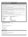
Installation and Assembly:
Outdoor Weather Resistant Enclosure
Models: HDS-OWRE-200
2300 White Oak Circle • Aurora, Il 60502 • (800) 865-2112 • Fax: (800) 359-6500 • www.peerless-av.com
ISSUED: 08-24-12 SHEET #: 180-9030-1
Note: Read entire instruction sheet before you start installation and assembly.
WARNING
• Do not begin to install your Peerless product until you have read and understood the instructions and warnings
contained in this Installation Sheet. If you have any questions regarding any of the instructions or warnings, for US
customers please call Peerless customer care at 1-800-865-2112, for all international customers, please contact
your local distributor.
• This product should only be installed by someone of good mechanical aptitude, has experience with basic building
construction, and fully understands these instructions.
• Due to outdoor environmental conditions such as heavy snow, hail, rain, etc. the environmental mount and
hardware must be inspected at least once a year. This product should not be exposed to high winds. A qualified
installer or inspector must check for signs of rust, loose fasteners, bent metal, etc. If evidence of excessive wear,
deterioration or any unsafe condition is observed, this product must be taken out of service immediately. Direct all
inquiries to customer care if you have any questions.
• Make sure that the supporting surface will safely support the combined load of the equipment and all attached
hardware and components.
• Never exceed the Maximum Load Capacity. See page one.
• If mounting to wood wall studs, make sure that mounting screws are anchored into the center of the studs. Use of
an "edge to edge" stud finder is highly recommended.
• Always use an assistant or mechanical lifting equipment to safely lift and position equipment.
• Tighten screws firmly, but do not overtighten. Overtightening can damage the items, greatly reducing their holding
power.
• This product was designed to be installed on the following wall construction only;
WALL CONSTRUCTION
HARDWARE REQUIRED
•
•
•
•
•
•
•
Included
Included
Included
Included
Contact Qualified Professional
Contact Qualified Professional
Contact Qualified Professional
Wood Stud
Wood Beam
Solid Concrete
Cinder Block
Metal Stud
Brick
Other or unsure?
Tools Needed for Assembly
• stud finder ("edge to edge" stud finder is recommended)
• phillips screwdriver
• drill
• 5/16" (8mm) bit for concrete and cinder block wall
• 5/32" (4mm) bit for wood stud wall
• level
• 7/16" open end wrench
• 5mm allen wrench
• 6mm allen wrench
Table of Contents
Parts List.............................................................................................................................................................................3, 4
Enclosure Wall installation ......................................................................................................................................................5
Enclosure Installation to ESA763PU Articulating Wall Mount................................................................................................. 7
Enclosure Installation to EPT650 Tilt Wall Mount .................................................................................................................16
Wireless Receiver Setup ......................................................................................................................................................18
2 of 22
ISSUED: 08-24-12 SHEET #: 180-9030-1
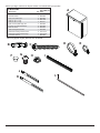
Before you begin, make sure all parts shown are included with your product.
Parts List
A
B
C
D
E
F
G
H
I
J
K
L
Description
wireless receiver enclosure, outdoor
concrete anchor
#14 x 2.5" wood screw
cable tie .187 x 7.5 lg.
cable tie .04 x 5.75 lg.
push-in round plastic plug, 3/8"
1/4-20 x 1/2 socket head screw
lock nut 1/4-20
cable management sheath
enclosure mounting bracket, small
enclosure mounting bracket, large
4 mm allen wrench
Qty.
1
2
2
2
4
4
6
6
1
2
2
1
A
HDS-OWRE-200
Part #
180-1018
590-0320
520-5033
590-1168
560-9711
590-9465
500-2093
530-5013
590-9468
120-T1195
120-T1196
560-9646
Parts may appear slightly different than illustrated.
B
D
C
G
F
H
E
I
J
L
K
3 of 22
ISSUED: 08-24-12 SHEET #: 180-9030-1
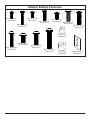
Adapter Bracket Fasteners
M4 x 12 mm (6)
(510-D1079)
M5 x 12 mm (4)
(520-D1064)
M5 x 25 mm (4)
(520-D1122)
M4 x 25 mm (4)
(510-D1082)
M6 x 12 mm (4)
(520-D1050) M6 x 20 mm (4)
(520-D1554)
M6 x 25 mm (4)
(520-D1211)
I.D. .22" (4)
(540-1057)
M8 x 12 mm (6)
(520-D1068)
M6 x 30 mm (4)
(520-D1067)
M8 x 25 mm (4)
(520-D1101)
M8 x 40 mm (4)
(520-D1152)
4 of 22
I.D. .34" (4)
(540-1059)
multi-washer (6)
(580-D1036)
ISSUED: 08-24-12 SHEET #: 180-9030-1
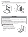
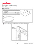
Enclosure Wall Installation
1
Open the wireless receiver enclosure (A) and remove the sub panel assembly as shown in fig. 1.1. Choose two
holes for securing the wireless receiver enclosure (A). Press in plastic plug (F) into the four remaining holes
shown in figure 1.2.
A
A
SUB PANEL
ASSEMBLY
F
MOUNTING
HOLES
fig. 1.1
fig. 1.2
WARNING
• Installer must verify that the supporting surface will safely support the combined load of the equipment and all
attached hardware and components.
• Tighten wood screws so that the enclosure is firmly attached, but do not overtighten. Overtightening can damage
the screws, greatly reducing their holding power.
• Never tighten in excess of 80 in. • lb (9 N.M.).
• Make sure that mounting screws are anchored into the center of the stud. The use of an "edge to edge" stud finder
is highly recommended.
• Hardware provided is for attachment of mount through standard thickness drywall or plaster into wood studs. Installers are responsible to provide hardware for other types of mounting situations.
Installation to Single Wood Stud Wall
5
Use a stud finder to locate the edges of the stud. Use of an
edge-to-edge stud finder is highly recommended. Based
on its edges, draw a vertical line down the stud’s center.
Place enclosure on wall as a template, making sure that two
vertical mounting holes are over the stud centerline. Level the
enclosure, and mark the center of the two holes. Drill two 5/32"
(4mm) dia. holes 2-1/2" (64mm) deep. Make sure that the
enclosure is level, secure it using two #14 x 2-1/2" wood screws
(C) as shown.
A
C
Skip to step 7.
5 of 22
ISSUED: 08-24-12 SHEET #: 180-9030-1
Enclosure Wall Installation to Solid Concrete or Cinder Block
WARNING
• Verify that you have a minimum of 1-3/8" (35mm) of actual concrete thickness in the hole to be used for the concrete anchors. Do not drill into mortar joints! Be sure to mount in a solid part of the block, generally 1" (25mm) minimum from the side of the block. Cinder block must meet ASTM C-90 specifications. It is suggested that a standard
electric drill on slow setting is used to drill the hole instead of a hammer drill to avoid breaking out the back of the
hole when entering a void or cavity.
• Concrete must be 2000 psi density minimum. Lighter density concrete may not hold concrete anchor.
• Make sure that the wall will safely support four times the combined load of the equipment and all attached hardware
and components.
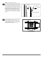
2
Make sure that the enclosure is level, use it as a
template to mark two mounting holes. Drill two 5/16"
(8mm) dia. holes to a minimum depth of 2-1/2"
(64mm). Insert anchors (B) in holes flush with wall
as shown (right). Place the enclosure over anchors
and secure with two #14 x 2-1/2" screws (C). Level,
then tighten all fasteners.
• Tighten screws so that wall plate is firmly attached,
but do not overtighten. Overtightening can damage
screws, greatly reducing their holding power.
CUTAWAY VIEW
B
3
• Never attach concrete expansion anchors to
concrete covered with plaster, drywall, or other
finishing material. If mounting to concrete surfaces
covered with a finishing surface is unavoidable,
the finishing surface must be counter bored as
shown below. Be sure concrete anchors do not
pull away from concrete when tightening screws. If
plaster/drywall is thicker than 5/8" (16mm), custom
fasteners must be supplied by installer.
plaster/
dry wall
A
C
• Always attach concrete expansion anchors directly
to load-bearing concrete.
concrete
Drill holes and insert anchors (B).
Place enclosure (A) over anchors (B) and secure with screws (C).
• Never tighten in excess of 80 in. • lb (9 N.M.).
wall
plate
B
2
WARNING
INCORRECT
concrete
surface
1
Tighten all fasteners.
SOLID CONCRETE
CORRECT
concrete
wall
plate
A
B
plaster/
dry wall
C
Skip to step 11.
CINDER BLOCK
6 of 22
ISSUED: 08-24-12 SHEET #: 180-9030-1
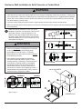
Enclosure Installation to ESA763PU Articulating Wall Mount
NOTE: If display has a VESA 400 horizontal
mounting pattern, skip to step 4 on page 8.
NOTE: For VESA 200x200 or VESA 200x100
mount hole patterns, skip to step 6 on page 11.
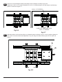
3
1/4-20 x 1.25" SCREWS
Remove four 1/4-20 x .6" screws using a 5 mm
allen wrench and loosen two 1/4-20 x 1.25" screws
1/2 turn to allow for display bracket adjustment.
1/4-20 x .6" SCREWS
3-1
To prevent scratching the display, set a cloth on a flat, level surface that will support the weight of the display.
Place display face side down and refer to display manufacturers instructions for removing obstructions from the
back of the display. Adjust display brackets to align with display mounting holes.
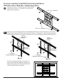
Measure horizontal mounting hole pattern and choose fixed stop-position from chart below.
horizontal mounting hole pattern
10-3/4" - 16-1/16" (273 - 408 mm)
15-1/16" - 21-9/16" (383 - 548 mm)
20-7/16" - 27-9/16" (519 - 700 mm)
fixed stop-position
#1
#2
#3
FIXED STOP-POSTION #3
FIXED STOP-POSTION #2
FIXED STOP-POSTION #1
7 of 22
ISSUED: 08-24-12 SHEET #: 180-9030-1
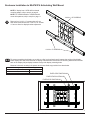
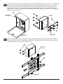
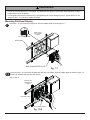
Open the wireless receiver enclosure (A) and remove the sub panel assembly as shown in fig. 4.1. Loosely attach
the small enclosure mounting brackets (J) to the wireless receiver enclosure (A) with two 1/4-20 x 1/2 socket
head screws (G) and two 1/4-20 nuts (H) as shown in fig. 4.2. NOTE: The enclosure mounting bracket can be
installed with the inside notch facing downward if additional side-to-side adjustment is needed. Position and
tighten the four 1/4-20 x 1/2 socket head screws (G) using 4mm allen wrench (L). Press in two plastic plugs (F)
into holes shown in figure 4.2.
4
A
G
A
SUB PANEL
ASSEMBLY
INSIDE NOTCH
H
F
fig. 4.1
5
J
fig. 4.2
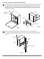
Attach the mounting brackets (J), open end of notch facing downward, to the left display bracket with two
1/4-20 x 1/2 socket head screws (G) and two 1/4-20 nuts (H) as shown in fig. 5.1.
Adjust the position of the enclosure (A) to your desired location as shown in fig. 5.2 Once in position, tighten the
four 1/4-20 x 1/2 socket head screws (G) using 4mm allen wrench (L).
DISPLAY
BRACKET
A
J
H
G
H
A
fig. 5.2
fig. 5.1
8 of 22
ISSUED: 08-24-12 SHEET #: 180-9030-1
Installing Adapter Brackets to Display
WARNING
• Tighten screws so display brackets are firmly attached to display. Do not tighten with excessive force.
Overtightening can cause stress damage to screws, greatly reducing their holding power and possibly causing
screw heads to become detached. Tighten to 40 in. • lb (4.5 N.M.) maximum torque.
• If screws don't get three complete turns in the display inserts or if screws bottom out and bracket is still not tightly
secured, damage may occur to display or product may fail.
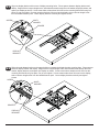
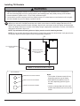
5-1
Select the screws from the baffled fastener pack that best fit your display and secure to display following step 5-2
on page 10.
NOTE: Top and bottom mounting holes must be used for attaching display brackets. Middle holes should also be
used where the fasteners and displays allow.
Verify that all holes are properly aligned, then tighten screws using a phillips screwdriver.
CENTER DISPLAY BRACKETS VERTICALLY AND
HORIZONTALLY ON BACK OF DISPLAY
X
DISPLAY
X
DISPLAY BRACKETS
Y
Y
NOTE: "X" dimensions should be equal.
"Y" dimensions should be equal.
9 of 22
ISSUED: 08-24-12 SHEET #: 180-9030-1
NOTE: enclosure removed for clarity.
5-2
Begin with the longest length screw, hand thread
screw through multi-washer, display brackets and
spacer in that order into display as shown below.
Screw must make at least three full turns into the
mounting hole and fit snug into place. Do not over
tighten. If screw cannot make three full turns into
the display, select a shorter length screw from
the baffled fastener pack. Repeat for remaining
mounting holes, level display brackets and tighten
screws.
DISPLAY
SPACER
MULTI-WASHER
SCREW
DISPLAY BRACKET
5-3
Center display brackets horizontally and vertically
on back of display. Tighten two 1/4-20 x 1.25"
screws. Reinstall four 1/4-20 x .6" screws using
a 5 mm allen wrench into appropriate fixed-stop
position from chart on page 7.
1/4-20 x 1.25" SCREWS
1/4-20 x .6" SCREWS
10 of 22
ISSUED: 08-24-12 SHEET #: 180-9030-1
Enclosure Installation to ESA763PU Articulating Wall Mount
VESA 200 x 200 or VESA 200 x 100 Mounting Pattern
Remove four 1/4-20 x .6" screws using a 5mm allen wrench
and loosen two 1/4-20 x 1.25" screws 1/2 turn to allow for
display bracket adjustment.
6
1/4-20 x 1.25" SCREWS
1/4-20 x .6" SCREWS
6-1
Remove four 1/4-20 self tapping screws to detach display brackets from outer mount holes of the universal
adapter bracket using a 5mm allen wrench as shown in figure 6.1. Reinstall four 1/4-20 self tapping screws to
secure display brackets to inner set of mounting holes on the universal adapter bracket as shown in figure 6.2.
OUTER
MOUNTING
INNER
HOLES
MOUNTING
HOLES
DISPLAY
BRACKETS
DISPLAY
BRACKETS
B
B
1/4-20 SELF
TAPPING SCREWS
1/4-20 SELF
TAPPING SCREWS
fig. 6.1
fig. 6.2
To prevent scratching the display, set a cloth on a
flat, level surface that will support the weight of the
display. Place display face side down and place the
universal adapter bracket onto display.
11 of 22
ISSUED: 08-24-12 SHEET #: 180-9030-1
6-2
Open the wireless receiver enclosure (A) and remove the sub panel assembly as shown in fig. 6.3. Loosely attach
the large enclosure mounting brackets (K) to the wireless receiver enclosure (A) with two 1/4-20 x 1/2 socket
head screws (G) and two 1/4-20 nuts (H) as shown in fig. 6.4. NOTE: The enclosure mounting bracket can be
installed with the inside notch facing downward if additional side-to-side adjustment is needed. Position and
tighten the four 1/4-20 x 1/2 socket head screws (G) using 4mm allen wrench (L). Press in two plastic plugs (F)
into holes shown in figure 6.4.
A
G
SUB PANEL
ASSEMBLY
A
K
H
F
fig. 6.4
fig. 6.3
6-3
Slide universal adapter bracket to the side to expopse the display bracket mounting slots. Attach the mounting
brackets (K), open end of notch facing downward, to the left display bracket with two 1/4-20 x 1/2 socket head
screws (G) and two 1/4-20 nuts (H) as shown in fig. 6.5.
G
DISPLAY
BRACKET
H
fig. 6.5
12 of 22
ISSUED: 08-24-12 SHEET #: 180-9030-1
6-4
Align one display bracket with one set of display mounting holes. Place spacers between display bracket and
display. Begin with the longest length screw, hand thread screw through the multi-washer, display brackets, and
spacer into display as shown. Screw must make at least three full turns into the mounting hole and fit snug into
place. Do not over tighten. If screw cannot make three full turns into the display, select a shorter length screw
from the baffled fastener pack. Center display brackets vertically and tighten screws.
MULTIWASHER
SCREW
SPACER
DISPLAY
BRACKET
6-5
Slide universal adapter bracket to the opposite side to expopse the display bracket mounting slots. Place spacers
between display bracket and display. Begin with the longest length screw, hand thread screw through the multiwasher, display brackets, and spacer into display as shown. Screw must make at least three full turns into the
mounting hole and fit snug into place. Do not over tighten. If screw cannot make three full turns into the display,
select a shorter length screw from the baffled fastener pack. Center display brackets vertically and tighten
screws.
SCREW
MULTIWASHER
SPACER
DISPLAY
BRACKET
13 of 22
ISSUED: 08-24-12 SHEET #: 180-9030-1
6-6
Center the universal adapter bracket horizontally on back of display as shown in figure 6.6.
Tighten two 1/4-20 x 1.25" screws. Reinstall four 1/4-20 x .6" screws using a 5 mm allen wrench into fixed-stop
position 1 as shown in figure 6.7.
1/4-20 x 1.25" SCREWS
FIXED STOP POSITION #1 WITH
1/4-20 x .6" SCREWS
fig. 6.6
fig. 6.7
6-7
Adjust the position of the enclosure (A) to your desired location as shown in fig. 6.8 Once in position, tighten the
four 1/4-20 x 1/2 socket head screws (G) shown in fig. 6.8 using 4mm allen wrench (L) and a 7/16" open end
wrench.
A
G
fig. 6.8
14 of 22
ISSUED: 08-24-12 SHEET #: 180-9030-1
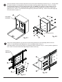
WARNING
• Do not lift more weight than you can handle. Use additional man power or mechanical lifting equipment to safely
handle placement of the display.
• Do not tighten screws with excessive force. Overtightening can cause damage to mount. Tighten M10 x 15 mm
screws to 40 in. • lb. (4.52 N.M.) maximum torque.
Mounting Flat Panel Display
7
Hook M10 x 15 mm screws into keyslots of wall arm adapter plate as shown figure 7.1.
1/4"
DISPLAY NOT
SHOWN FOR
CLARITY
M10 X 15 MM SCREW
WALL ARM
WALL ARM ADAPTER PLATE
fig. 7.1
7-1
Insert two M10 x 15 mm screws (included with wall arm) into bottom holes of adapter plate as shown in figure 7.2.
Tighten all fasteners with a 6 mm allen wrench.
Skip to step 11.
DISPLAY NOT
SHOWN FOR
CLARITY
ADAPTER PLATE
M10 X 15 MM SCREW
fig. 15.2
15 of 22
ISSUED: 08-24-12 SHEET #: 180-9030-1
Enclosure Installation to EPT650 Tilt Wall Mount
8
Open the wireless receiver enclosure (A) and remove the sub panel assembly as shown in fig. 8.1. Loosely attach
the small enclosure mounting brackets (J) to the wireless receiver enclosure (A) with two 1/4-20 x 1/2 socket
head screws (G) and two 1/4-20 nuts (H) as shown in fig. 8.2. NOTE: The enclosure mounting bracket can be
installed with the inside notch facing downward if additional side-to-side adjustment is needed. Position and
tighten the four 1/4-20 x 1/2 socket head screws (G) using 4mm allen wrench (L). Press in two plastic plugs (F)
into holes shown in figure 8.2.
A
G
SUB PANEL
ASSEMBLY
F
INSIDE NOTCH
9
J
H
fig. 8.1
fig. 8.2
Attach the mounting brackets (J), open end of notch facing downward, to the left tilt bracket with two
1/4-20 x 1/2 socket head screws (G) and two 1/4-20 nuts (H) as shown in fig. 9.1. Adjust the position of the
enclosure (A) to your desired location and tighten the four 1/4-20 x 1/2 socket head screws (G) using 4mm allen
wrench (L).
H
G
A
LEFT TILT BRACKET
fig. 9.1
16 of 22
ISSUED: 08-24-12 SHEET #: 180-9030-1
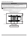
Installing Tilt Brackets
WARNING
• Tighten screws so adapter brackets are firmly attached. Do not tighten with excessive force. Overtightening
can cause stress damage to screws, greatly reducing their holding power and possibly causing screw heads to
become detached. Tighten to 40 in. • lb (4.5 N.M.) maximum torque.
• If screws don't get three complete turns in the display inserts or if screws bottom out and bracket is still not tightly
secured, damage may occur to display or product may fail.
10
To prevent scratching the display, set a cloth on a flat, level surface that will support the weight of the display. Place
display face side down. If display has knobs on the back, remove them to allow the adapter brackets to be attached. Place adapter brackets on back of display, align to holes, and center on back of display as shown below.
Attach the adapter brackets to the back of the display using the appropriate combination of screws, multi-washers,
and spacers as shown in figure 10.1.
NOTE: Top and bottom mounting holes on display must be used for attaching brackets.
NOTE: Be sure to attach tilt brackets with tilt locking screws facing outward as shown below. Verify that all holes
are properly aligned, and then tighten screws using a phillips screwdriver.
X
TILT LOCKING SCREWS
FACE OUT
CENTER BRACKETS
VERTICALLY ON BACK
OF DISPLAY
X
NOTE: "X" dimensions should be equal.
MULTI-WASHER
MEDIUM HOLE FOR M5 SCREWS
SMALL HOLE FOR M4 SCREWS
LARGE HOLE FOR M6 SCREWS
17 of 22
Notes:
• The number of fasteners used will vary,
depending upon the type of display.
• Multi-washers and spacers may not
be used, depending upon the type of
display.
• Use the corresponding hole in the multiwasher that matches your screw size as
shown.
ISSUED: 08-24-12 SHEET #: 180-9030-1
10-1 Begin with longer length screw, hand thread through multi-washer, tilt bracket and spacer in that order into display
as shown below. Screw must make at least three full turns into the mounting hole and fit snug into place. Do not
over tighten. If screw cannot make three full turns into the display, select a longer length screw from the baffled
fastener pack. Repeat for remaining mounting holes, level brackets and tighten screws.
fig. 10.1
DISPLAY
MULTI-WASHER
SPACER
SCREW
TILT BRACKET
If you have any questions, please call Peerless customer care at 1-800-865-2112.
18 of 22
ISSUED: 08-24-12 SHEET #: 180-9030-1
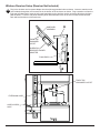
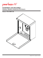
Wireless Receiver Setup (Receiver Not Included)
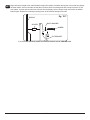
11
Plug in the wireless receiver power adapter into the triple tap grounded outlet as shown. Insert an extension cord
(not included) through the cord access hole in the bottom of the enclosure as shown. Plug entension cord into the
triple tap grounded outlet. Insert the sub panel assembly into the wireless receiver enclosure (A) above the foam
pads as shown. Push the sub panel assembly down and towards the rear of the until it makes contact with the
back wall and the bottom of the enclosure.
SUB PANEL
ASSEMBLY
A
TRIPLE TAP
GROUNDED
OUTLET
WIRELESS
RECEIVER POWER
ADAPTER
FOAM PADS
TRIPLE TAP
GROUNDED OUTLET
EXTENSION CORD
CORD ACCESS
HOLE
19 of 22
ISSUED: 08-24-12 SHEET #: 180-9030-1
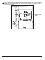
12
Insert the power cord from your display through the cord access hole in the bottom of the enclosure as shown. Plug
the power cord into the triple tap grounded outlet. Coil up the excess cord and secure with a cable tie (E). Store
excess cord inside enclosure.
DISPLAY POWER
CORD
CORD ACCESS
HOLE
20 of 22
ISSUED: 08-24-12 SHEET #: 180-9030-1
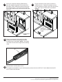
13
10
Insert your component cable(s) (HDMI shown)
from your display through the cord access hole in
the bottom of the enclosure as shown and plug into
the wireless receiver. Coil up the excess cord and
secure with a cable tie (D). Store excess cord inside
enclosure.
14
Plug the wireless receiver power cord into the
wireless receiver. Position the wireless receiver
into the enclosure as shown, then close the elosure
door. Door may be locked with key provided if
desired.
WIRELESS
RECEIVER POWER
CORD
COMPONENT
CABLE
15
Place the component cord(s) inside the cable
management sheath (I) by pushing the cables
through the slit in the sheath. NOTE: The sheath
may need to be trimmed to length before installing
cords.
I
16
Plug extension cord into power source.
To complete the installation of your wireless system, please refer to the HD Flow™ User's Manual and the HD
Flow™ Install Guide included.
21 of 22
ISSUED: 08-24-12 SHEET #: 180-9030-1
© 2012 Peerless Industries, Inc.
Peerless-AV® is a registered trademark of Peerless Industries, Inc. All rights reserved.
All other brand and product names are trademarks or registered trademarks of their respective owners.
LIMITED WARRANTY
Peerless Industries, Inc. (“Peerless-AV®”) warrants to original end-users of Peerless-AV® products that Peerless-AV® products will be free from defects in material
and workmanship, under normal use, for the periods listed below, from the date of purchase by the original end-user. At its option, Peerless-AV® will repair or
replace with new or refurbished products or parts, or refund the purchase price of any Peerless-AV® product which fails to conform with this warranty.
In no event shall the duration of any implied warranty of merchantability or fitness for a particular purpose be longer than the period of the applicable
express warranty set forth above. Some states do not allow limitations on how long an implied warranty lasts, so the above limitation may not apply to you.
This warranty does not cover damage caused by (a) service or repairs by the customer or a person who is not authorized for such service or repairs by PeerlessAV®, (b) the failure to utilize proper packing when returning the product, (c) incorrect installation or the failure to follow Peerless-AV®’s instructions or warnings
when installing, using or storing the product, or (d) misuse or accident, in transit or otherwise, including in cases of third-party actions and force majeure. This
warranty also does not cover corrosion or rust resulting from damaged, scratched or chipped paint or other surfaces.
In no event shall Peerless-AV® be liable for incidental or consequential damages or damages arising from the theft of any product, whether or not
secured by a security device which may be included with the Peerless-AV® product. Some states do not allow the exclusion or limitation of incidental or
consequential damages, so the above limitation or exclusion may not apply to you.
This warranty is in lieu of all other warranties, express or implied, and is the sole remedy with respect to product defects. No dealer, distributor, installer or other
person is authorized to modify or extend this Limited Warranty or impose any obligation on Peerless-AV® in connection with the sale of any Peerless-AV® product.
This warranty gives specific legal rights, and you may also have other rights which vary from state to state.
Product
Warranty Period
Mounts
Furniture
Cables
Cleaning Products
Electronic Products and components
5 years
1 year
25 years
1 year
1 year
www.peerless-av.com
22 of 22
© 2012 Peerless Industries, Inc.
ISSUED: 08-24-12 SHEET #: 180-9030-1