1
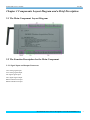
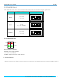
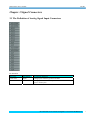
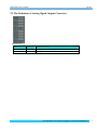
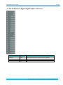
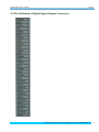
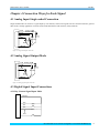
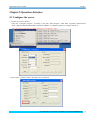
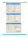
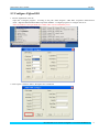
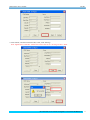
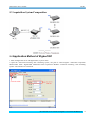
Zigbee1081
User’s Manual
Beijing ART Technology Development Co., Ltd.
Zigbee1081 user’s manual
V6.007
Contents
Contents ............................................................................................................................................................................. 2
Chapter 1 Overview ........................................................................................................................................................... 3
Chapter 2 Components Layout Diagram and a Brief Description .................................................................................... 5
2.1 The Main Component Layout Diagram ............................................................................................................... 5
2.2 The Function Description for the Main Component ............................................................................................ 5
2.2.1 Signal Input and Output Connectors ......................................................................................................... 5
2.2.2 Mode DIP Switch ...................................................................................................................................... 6
2.2.3 Status Indicator.......................................................................................................................................... 6
2.2.4 Reset Button.............................................................................................................................................. 6
Chapter 3 Signal Connectors............................................................................................................................................. 7
3.1 The Definition of Analog Signal Input Connectors.............................................................................................. 7
3.2 The Definition of Analog Signal Output Connector ............................................................................................ 8
3.3 The Definition of Digital Signal Input Connectors .............................................................................................. 9
3.4 The Definition of Digital Signal Output Connectors ......................................................................................... 10
3.5 The Definition of RS232 Serial Port ...................................................................................................................11
3.6 The Definition of RS485 Interface......................................................................................................................11
Chapter 4 Connection Ways for Each Signal................................................................................................................... 12
4.1 Analog Input Single-ended Connection ............................................................................................................. 12
4.2 Analog Signal Output Mode............................................................................................................................... 12
4.3 Digital Signal Input Connections ....................................................................................................................... 12
4.3.1 Dry contact signal input mode ................................................................................................................ 12
4.3.2 Wet contact signal common anode input mode ....................................................................................... 13
4.3.3 Wet contact signal common cathode input mode .................................................................................... 13
4.4 Digital Signal Output Connections .................................................................................................................... 13
Chapter5 Operation Interface.......................................................................................................................................... 14
5.1 Configure the server........................................................................................................................................... 14
5.2 Configure Zigbee1081 ....................................................................................................................................... 16
5.3 Acquisition System Composition....................................................................................................................... 18
5.4 Application Method of Zigbee1081 ................................................................................................................... 18
Chapter6 Notes and Warranty Policy .............................................................................................................................. 20
6.1 Notes .................................................................................................................................................................. 20
6.2 Warranty Policy.................................................................................................................................................. 20
BUY ONLINE at art-control.com/englishs or CALL 86-10-51289836(CN)
2
Zigbee1081 user’s manual
V6.007
Chapter 1 Overview
ZigBee is the specification of a low-cost, low-power wireless communications solution, meant to be integrated as the
main building block of ubiquitous networks.
Zigbee1081 is a data acquisition module based on ZigBee wireless transmission. It can sample data and transfer the data
to processing device to constitute the laboratory, product quality testing center and systems for different areas of data
acquisition, waveform analysis and processing. It may also constitute the monitoring system for industrial production
process.
Unpacking Checklist
Check the shipping carton for any damage. If the shipping carton and contents are damaged, notify the local dealer or
sales for a replacement. Retain the shipping carton and packing material for inspection by the dealer.
Check for the following items in the package. If there are any missing items, contact your local dealer or sales.
¾ Zigbee1081
¾ ART Card
a) user’s manual (pdf)
b) drive
c) catalog
¾ Warranty Card
Product Information
z
z
z
z
z
z
z
Core Module: 66MHz main frequency 32-bit RISC processor
Memory
2MB NorFlash
512KB SRAM
Communication Interface
One Zigbee module, external antenna
One 3-wire RS232 serial port, baud rate up to 115200Kbps
One isolation RS485 interface
Other Devices
One recalibrate external RTC
4 LED indicators
Hardware Watchdog to ensure the system reliability
Support CF card (optional)
Display System (optional)
320 x 240 monochrome LCD, human display device
4-wire resistive touch screen human-machine interfaces
Analog/Digital Signal
Analog Input: 16-ch 16-bit analog input, range ±10V, ±5V, ±2.5V, 0~10V, 0~5V (isolated)
Analog Output: 8-ch 12-bit analog output , range 0~5V, 0~10V, ±5V, ±10V (isolated)
Digital Input: 16-ch dry contact input (default) or 8-ch wet contact common anode/cathode
Digital Output: 16-ch relay output
System Power Supply:
9V~30V
BUY ONLINE at art-control.com/englishs or CALL 86-10-51289836(CN)
3
Zigbee1081 user’s manual
z
V6.007
Operation Temperature
-40℃~+80℃ (without LCD screen)
0℃~+70℃ (with LCD screen)
FEATURES
Analog Input
¾
¾
¾
¾
¾
¾
¾
¾
¾
Input Range: ±10V, ±5V, ±2.5, 0~10V, 0~5V
16-bit resolution
Analog Input Mode: 16SE
AD Conversion Time: ≤1.25us
Non-linear error: ±1LSB(Maximum)
System Measurement Accuracy: 0.1%
Isolation Voltage: 3000V
Operating Temperature Range: 0℃~ +50℃
Storage Temperature Range: - 20℃~ +70℃
Analog Output
¾
¾
¾
¾
¾
¾
¾
¾
¾
Output Range: ±10V, ±5V, 0~10V, 0~5V
12-bit resolution
Set-up Time: 10μs
Channel No.: 8-channel
Isolation Voltage: 3000V
Non-linear error: ±1LSB(Maximum)
Output error(full-scale): ±1LSB
Operating Temperature Range: 0℃~ +50℃
Storage Temperature Range: - 20℃~ +70℃
Digital Input
¾
¾
¾
¾
¾
Channel No.: 16-channel
Input Type: dry contact, wet contact
Input high level: +4V~+30V
Input low level: 0~+1V
Isolated voltage: 3000V
Digital Output
¾
¾
¾
Channel No.: 16-channel
Output Type : power relay
Contact Rating: 250VAC@5A
Dimension
¾
226mm(L)*140mm(W)*37mm(H)
BUY ONLINE at art-control.com/englishs or CALL 86-10-51289836(CN)
4
Zigbee1081 user’s manual
V6.007
Chapter 2 Components Layout Diagram and a Brief Description
2.1 The Main Component Layout Diagram
2.2 The Function Description for the Main Component
2.2.1 Signal Input and Output Connectors
AD: analog signal input
DA: analog signal output
DI: digital signal input
DO: digital signal output
RS232: RS232 serial port
RS485: RS485 serial port
BUY ONLINE at art-control.com/englishs or CALL 86-10-51289836(CN)
5
Zigbee1081 user’s manual
V6.007
2.2.2 Mode DIP Switch
DIP: Mode DIP Switch. It can be set to RS232 mode, RS485 mode and CONFIG configure Zigbee mode.
DIP Switch Status
Mode
Graphic
ON
1, 2, 5=ON
RS232
3, 4, 6=OFF
1
2
3
4
5
6
2
3
4
5
6
2
3
4
5
6
ON
6= ON
RS485
1, 2, 3, 4, 5= OFF
1
ON
3, 4, 5=ON
CONFIG
1, 2, 6=OFF
1
2.2.3 Status Indicator
RUN
ZIGBEE
POWER
CF Card
RUN: Program run indicator
POWER: power supply indicator
CF Card: CF card indicator
ZIGBEE: Zigbee transmission mode indicator
2.2.4 Reset Button
DEFAULT: System reset button, reset the system to the initial value. The default initial value: baud rate 9600bps, address 1.
BUY ONLINE at art-control.com/englishs or CALL 86-10-51289836(CN)
6
Zigbee1081 user’s manual
V6.007
Chapter 3 Signal Connectors
3.1 The Definition of Analog Signal Input Connectors
Pin definition
Pin name
Pin feature
Pin function definition
AI0~AI15
Input
Analog input, reference ground is AGND.
AD.COM
GND
Analog ground. This AGND pin should be connected to the
system’s AGND plane.
BUY ONLINE at art-control.com/englishs or CALL 86-10-51289836(CN)
7
Zigbee1081 user’s manual
V6.007
3.2 The Definition of Analog Signal Output Connector
Pin definition:
Pin Name
Type
Function definition
AO0~AO7
Input
Analog output, reference ground is DAGND
DA.COM
GND
Analog ground.
BUY ONLINE at art-control.com/englishs or CALL 86-10-51289836(CN)
8
Zigbee1081 user’s manual
V6.007
3.3 The Definition of Digital Signal Input Connectors
Pin Definition:
Signal Name
Type
Function definition
DI0-DI15
Input
Digital signal input pins, reference ground is DGND.
DIGND
Input
Digital input (dry contact) common terminal.
DICOM0~DICOM1
Input
Digital input(wet contact) common terminal
BUY ONLINE at art-control.com/englishs or CALL 86-10-51289836(CN)
9
Zigbee1081 user’s manual
V6.007
3.4 The Definition of Digital Signal Output Connectors
BUY ONLINE at art-control.com/englishs or CALL 86-10-51289836(CN)
10
Zigbee1081 user’s manual
V6.007
Pin Definition:
Pin Name
Type
Function definition
COM0~COM15
Output
The positive terminal of digital output.
NO0~NO15
Output
The negative terminal of digital output.
3.5 The Definition of RS232 Serial Port
9
8
7
6
5
GND
4
3
RXD
2
TXD
1
CN1 pin definition:
Pin Name
Function definition
TXD
Send data
RXD
Receive data
GND
Signal ground.
3.6 The Definition of RS485 Interface
Pin Name
Function definition
POWER
Power supply
GND
Power supply ground
EGND
Signal ground
DATA+
Positive terminal of the data
DATA-
Negative terminal of the data
BUY ONLINE at art-control.com/englishs or CALL 86-10-51289836(CN)
11
Zigbee1081 user’s manual
V6.007
Chapter 4 Connection Ways for Each Signal
4.1 Analog Input Single-ended Connection
Single-ended mode can achieve a signal input by one channel, and several signals use the common reference ground.
This mode is widely applied in occasions of the small interference and relatively many channels.
Figure 4.1 single-ended input connection
4.2 Analog Signal Output Mode
Figure 4.3 analog signal output connection
4.3 Digital Signal Input Connections
4.3.1 Dry Contact Signal Input Mode
DIGND
DI0
DI1
DI2
DI15
BUY ONLINE at art-control.com/englishs or CALL 86-10-51289836(CN)
12
Zigbee1081 user’s manual
V6.007
4.3.2 Wet Contact Signal Common Anode Input Mode
DICOM1
DICOM0
DI0
DI8
DI1
DI9
DI2
DI10
DI7
DI15
4.3.3 Wet Contact Signal Common Cathode Input Mode
DICOM1
DICOM0
DI0
DI8
DI1
DI9
DI2
DI10
DI7
DI15
4.4 Digital Signal Output Connections
COM0~COM15 are relay output positive terminal, NO0~NO15 are relay output negative terminal.
COM0
NO0
COM15
NO15
BUY ONLINE at art-control.com/englishs or CALL 86-10-51289836(CN)
13
Zigbee1081 user’s manual
V6.007
Chapter5 Operation Interface
5.1 Configure the server
1. Connect the server to the PC.
Open the “Configure program”: according to the path “Start--Program—ART Data Acquisition Measurement
Suite—Zigbee10XX Distributed Data Acquisition Module—Configure program” to configure the server.
Note: the server’s baud rate is 115200, and it can’t be modified by users.
2. Click “Open”, and then “Enter”, the figures are as followed.
BUY ONLINE at art-control.com/englishs or CALL 86-10-51289836(CN)
14
Zigbee1081 user’s manual
V6.007
4. Click “Read”, and then set the PAN ID, at last, click “Setting.”. PAN ID’s range is 1-3FFF.
BUY ONLINE at art-control.com/englishs or CALL 86-10-51289836(CN)
15
Zigbee1081 user’s manual
V6.007
5.2 Configure Zigbee1081
1. Connect Zigbee1081 to the PC.
Open the “Configure program”: according to the path “Start--Program—ART Data Acquisition Measurement
Suite—Zigbee10XX Distributed Data Acquisition Module—Configure program” to configure the server.
Note: the module’s serial port baud rate is 9600, and it can’t be modified by users.
2. Click “Open”, and then “Enter”, the figures are as followed.
BUY ONLINE at art-control.com/englishs or CALL 86-10-51289836(CN)
16
Zigbee1081 user’s manual
V6.007
4. Click “Read”, and then set the PAN ID, at last, click “Setting.”
Note: Zigbee1081’s “PAN ID” must be the same as the server’s. Its range is also 1-3FFF.
BUY ONLINE at art-control.com/englishs or CALL 86-10-51289836(CN)
17
Zigbee1081 user’s manual
V6.007
5.3 Acquisition System Composition
5.4 Application Method of Zigbee1081
1. After configure the server and Zigbee1081, re-power them.
2. Open the “Advanced measuring and controlling system”, the path is “Start--Program—ART Data Acquisition
Measurement Suite—Zigbee10XX Distributed Data Acquisition Module—Advanced measuring and controlling
system”. The interface is as followed.
BUY ONLINE at art-control.com/englishs or CALL 86-10-51289836(CN)
18
Zigbee1081 user’s manual
V6.007
3. Search the module.
BUY ONLINE at art-control.com/englishs or CALL 86-10-51289836(CN)
19
Zigbee1081 user’s manual
V6.007
Chapter6 Notes and Warranty Policy
6.1 Notes
In our products’ packing, user can find a user manual, a Zigbee1081 module and a quality guarantee card. Users must
keep quality guarantee card carefully, if the products have some problems and need repairing, please send products
together with quality guarantee card to ART, we will provide good after-sale service and solve the problem as quickly
as we can.
When using Zigbee1081, in order to prevent the IC (chip) from electrostatic harm, please do not touch IC (chip) in the
front panel of Zigbee1081 module.
6.2 Warranty Policy
Thank you for choosing ART. To understand your rights and enjoy all the after-sales services we offer, please read the
following carefully.
1. Before using ART’s products please read the user manual and follow the instructions exactly. When sending in
damaged products for repair, please attach an RMA application form which can be downloaded from:
www.art-control.com.
2. All ART products come with a limited two-year warranty:
¾ The warranty period starts on the day the product is shipped from ART’s factory
¾ For products containing storage devices (hard drives, flash cards, etc.), please back up your data before sending
them for repair. ART is not responsible for any loss of data.
¾ Please ensure the use of properly licensed software with our systems. ART does not condone the use of pirated
software and will not service systems using such software. ART will not be held legally responsible for products
shipped with unlicensed software installed by the user.
3. Our repair service is not covered by ART's guarantee in the following situations:
¾ Damage caused by not following instructions in the User's Manual.
¾ Damage caused by carelessness on the user's part during product transportation.
¾ Damage caused by unsuitable storage environments (i.e. high temperatures, high humidity, or volatile chemicals).
¾ Damage from improper repair by unauthorized ART technicians.
¾ Products with altered and/or damaged serial numbers are not entitled to our service.
4. Customers are responsible for shipping costs to transport damaged products to our company or sales office.
5. To ensure the speed and quality of product repair, please download an RMA application form from our company
website.
BUY ONLINE at art-control.com/englishs or CALL 86-10-51289836(CN)
20


![取扱説明書 - FAST CORPORATION[株式会社ファースト]](http://vs1.manualzilla.com/store/data/006530365_2-8a4dc036f829a07b89dfac9c2cde8f67-150x150.png)