1
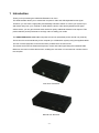
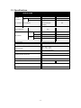
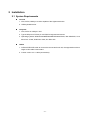
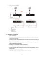
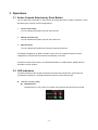
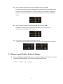
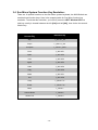
USB KVM EXTENDER OVER CAT.5 User’s Manual DS-52100 Index 1 2 3 INTRODUCTION ........................................................................................................................ 2 1.1 FEATURES.............................................................................................................. 3 1.2 PACKAGE CONTENTS .............................................................................................. 3 1.3 SPECIFICATIONS ..................................................................................................... 4 INSTALLATION .......................................................................................................................... 5 2.1 SYSTEM REQUIREMENTS ........................................................................................ 5 2.2 PHYSICAL DIAGRAM ................................................................................................ 6 2.3 HARDWARE INSTALLATION ....................................................................................... 8 OPERATIONS ............................................................................................................................ 9 3.1 ACTIVE CONSOLE SELECTION BY PUSH BUTTON ...................................................... 9 3.2 LED INDICATORS.................................................................................................... 9 3.3 BUZZER SOUND DISABLE / ENABLE BY HOTKEY ....................................................... 11 3.4 SUN MICRO SYSTEM FUNCTION KEY EMULATION ................................................... 12 -1- 1 Introduction Thank you for purchasing the USB KVM Extender over Cat.5. This KVM extender allows you to extend the computer’s video and USB keyboard/mouse signal. Therefore, you now have a high quality and durability extension solution to control your system up to 200 meters away from your computer or KVM. With the built-in video and keyboard/mouse signal enhancement, you can gain the best video resolution quality. Additional software is not required. This product delivers perfect performance and high value to satisfy your needs. The USB KVM Extender over Cat.5 comprises a local unit (transmitter) and a remote unit (receiver). The local unit is connected directly to the computer (or a KVM switch system) using the supplied cables. The user console (keyboard, mouse and monitor) is attached to the remote unit. The remote and local units extend the keyboard, mouse and video signal along the Cat5/5e/6 cable. Moreover, the local unit offers dual access, enabling the connection of a second user console close to the computer. Local Unit: Transmitter Remote Unit: Receiver -2- 1.1 Features 1. Extends the Keyboard / Video / Mouse signal by a Cat5/5e/6 cable. 2. Dual console operation - Control your system from both the local and remote unit. 3. Push button at local side to select active console. 4. Available active console options: local console / remote console / both consoles. 5. Supports connection of USB keyboard/mouse for local and remote console arbitrarily. 6. Supports keyboard/mouse connection of USB interface to computer at local side arbitrarily. 7. Supports high resolution video - Up to 1280x1024 @ 60Hz for distances of up to 200 meters. 8. Supports VGA, SVGA and multisync monitors. 9. DDC2B support for remote monitor. 10. Adjustable control of focus and brightness to improve video quality at remote side. 11. No software or driver installation required. 12. Compatible with most commonly used operating systems like DOS, Windows 98SE/ME/2000/XP/2003 Server/Vista/7, Linux, Mac OS9/OSX and Sun Microsystems. 13. Supports BIOS level operation. 14. Plug and Play. 15. Supports Microsoft Intellimouse 3 ~ 5 key mouse & Microsoft Natural Keyboard Pro series. 16. Supports SUNMICRO system function key emulation. 17. LEDs on each device to indicate the active console and connection status. 18. Firmware upgradeable. 1.2 Package Contents The product you purchased should contain the equipment and accessories shown as follows: 1. 1 x Local Unit 2. 1 x Remote Unit 3. 1 x Custom combo 4-in-1 cable. 4. 2 x External power adaptor DC 5V 2A 5. 1 x User’s Manual -3- 1.3 Specifications DS-51200 MODLE NAME Transmitter VGA Output Console Connectors USB Receiver HDB-15 ( Female ) HDB-15 ( Female ) Keyboard USB Type A (Female) USB Type A (Female) mouse USB Type A (Female) USB Type A (Female) PC Connectors Video (KB/MS) HDB-15 ( Female ) (PS/2 & USB signal combined) Extension Port RJ-45 FOR KB/MS/VGA Extension Video Adjustment Focus LED indicator Remote Local / Remote Switch Button 1 x VR N/A Brightness Local N/A 1 x VR Selected Right Red LED Right Red LED Active Right Green LED Right Green LED Selected Left Red LED Left Red LED Active Left Green LED Left Green LED Yes. No. DDC Supported REMOTE Support DDC2B Extension Cable Type & Length CAT5, CAT5E, CAT6. Video Resolution 1920 x 1200 – 50 m 1600 x 1200 – 100 m 1400 x 900 – 150 m 1280x1024(60HZ)@200m Firmware Upgrade Yes Operating Systems Supported Max. Length : 200M Windows 98SE/ME/2000/XP/2003 Server/Vista/7, Linux Mac OS9/OSX and Sun Microsystems Power Supply DC 5V / 2A Adaptor Dimension ( L x W x H ) 127 x 67 x 27 mm Unit Weight 246 g Housing material Metal Operating Temperature 32~ 122°F Humidity 0%~80%RH -4- 243 g (0~ 50°C ) 2 Installation 2.1 System Requirements Console 1. VGA, SVGA, Multisync monitor capable of the highest resolution. 2. USB keyboard/mouse. Computer 1. VGA, SVGA or multisync card. 2. Type A USB port or PS/2 6 pin mini-DIN for keyboard and mouse. 3. Operating systems: Windows 98/98SE/2000/ME/XP/2003/Vista/7, Mac OS9/OSX, Linux Kernel 2.3 or later, Solaris 8 or later, Sun Micro OS. Cables 1. CAT5/CAT5E/CAT6 cable to connect the remote and local unit, the supported maximum length of this cable is 200 meters. 2. Custom combo 4-in-1 cable (accessories). -5- 2.2 Physical Diagram Transmitter Front View 1 2 3 4 5 Reset switch LED indicators Push button USB keyboard USB mouse Rear View 1 2 3 4 Cat5 Video to local monitor Video/KB/MS to PC Power jack -6- Receiver Front View 1 2 3 4 5 Rear View 1 2 3 4 Reset switch LED indicators USB keyboard USB mouse Video adjusted skews Cat5 Upgrade Video to local monitor Power jack Reset Switch : Press the Reset switch if you want to reset the system. This switch must be pushed with a thin object like the end of a paper clip, or a ball point pen. Firmware download connector The min-USB female connector on the rear of the KVM switch is for a firmware upgrade function. To update your KVM firmware, please contact your dealer. -7- Cable Connection Diagram 1 2 3 4 5 Monitor PC Video/KB/MS USB mouse USB keyboard 2.3 Hardware Installation 1. Switch off all devices. 2. Connect your monitor, USB keyboard/mouse to the local unit, if you want to control your system at the local console. 3. Connect your monitor, USB keyboard/mouse to the remote unit, if you want to control your system at the remote console. 4. Connect the remote and local unit by using a CAT5/CAT5E/CAT6 cable; the supported maximum cable length is 200 meters. 5. Connect the 5V power supply to power on the local unit. 6. Connect the 5V power supply to power on the remote unit. 7. Connect video and/or USB keyboard/mouse of local unit and computer/KVM by using the supplied cables. 8. Turn on your computer if it was turned off. 9. Adjust video quality by using brightness or focus skew if necessary. -8- 3 Operations 3.1 Active Console Selection by Push Button You can press the push button on the local unit to change the active console of operation. There are three types of active console configurations: 1. Local Console Only You can operate the system only from the local unit. 2. Remote Console Only You can operate the system only from the remote unit. 3. Both Consoles You can operate the system from both the local and remote unit. The default configuration is “Both Consoles” mode. Once you change the active console configuration, it will be saved and will not be affected by unit reset. The active console can be shown via “Selected Indicators” of LED indicator, please refer the description of next sections 3.2 LED Indicators The LED indicators of the remote console are the same as the local ones, if both units are connected successfully; or all LED indicators at remote console will turn OFF. Selected Indicators (RED) Both Selected: Indicates that you can control your system from both the local and remote console. -9- Local Selected: Indicates that you can control your system from the local console only. Remote Selected: Indicates that you can control your system from the remote console only. Active Indicators (GREEN) Indicates the connection status: Local Indicator: Indicates whether the connection between the local unit and computer is ready or not. Remote Indicator: Indicates whether the connection between the local and remote unit is ready or not. Examples of LED Indicators: Both consoles are selected, local active is ON, remote active is OFF: It means that the connection between the local unit and the computer is ready, but the CAT5 connection between the local and remote unit is not ready. In this case, you can only control your system at the local console, because the remote console is not connected successfully. The following indicators are shown at the local console, all LED indicators will be OFF at the remote console because of disconnection. - 10 - Both consoles are selected, local active is OFF, remote active is ON: It means that the CAT5 connection between the local and remote unit is ready, but the local unit is not connected to the PC correctly or the PC is not turned on. In this case, you cannot control your system from any console, because the PC is not available to control. Both consoles are selected, local active is ON, remote active is ON: Connection of the local and remote unit is successful; you can control your system at the local and the remote console. Active console is inconsistent with selected console: You cannot control your system if the active console is inconsistent with the selected. 3.3 Buzzer sound Disable / Enable by Hotkey Press <Left Shift> or <Right Shift> twice, then <B> and <Enter>. The buzzer sound will be disabled / enabled alternately. The buzzer sound default setting is ON. < Shift > → < Shift > → <B> → <Enter> - 11 - 3.4 Sun Micro System Function Key Emulation: There are 16 special functions on the Sun Micro system keyboard, the KVM Switch can emulate these function keys. Here is the mapping table for Sun Micro function key emulation. To activate this emulation, you have to press the LEFT Window KEY first (this key usually is located between the left [Ctrl] and left [Alt]), then choice the second relative key. Sun Micro System Function Key Emulation Key Stop L_Win & L_Alt Props L_Win & L_Ctrl Compose L_Win & L_Shift Front L_Win & F1 Open L_Win & F2 Find L_Win & F3 Again L_Win & F4 Undo L_Win & F5 Copy L_Win & F6 Paste L_Win & F7 Cut L_Win & F8 Help L_Win & F11 Power L_Win & F12 Mute L_Win & 1 Volume Down L_Win & 2 Volume UP L_Win & 3 - 12 - Disclaimer Information in this document is subject to change without notice. The manufacturer does not make any representations or warranties (implied or otherwise) regarding the accuracy and completeness of this document and shall in no event be liable for any loss of profit or any other commercial damage, including but not limited to special, incidental, consequential, or other damages. No part of this document may be reproduced or transmitted in any form by any means, electronic or mechanical, including photocopying, recording or information recording and retrieval systems without the express written permission of the manufacturer. All brand names and product names used in this document are trademarks, or registered trademarks of their respective holders. FCC Statement This device generates and uses radio frequency and may cause interference to radio and television reception if not installed and used properly. This has been tested and found to comply with the limits of a Class B computing device in accordance with the specifications in Part 15 of the FCC Rules. These specifications are designed to provide reasonable protection against such interference in a residential installation. However, there is no guarantee that interference will not occur in a particular installation. If this device does cause harmful interference to radio or television reception, which can be determined by plugging the device in and out, the user can try to correct the interference by one or more of the following measures: Reorient or relocate the receiving antenna. Increase the separation between the device and receiver. Connect the computer into an outlet on a circuit different from that to which the receiver is connected. Consult the dealer or an experienced radio/TV technician for help. - 13 -