1
The calling party then dials in a two or three digit
number depending upon the position of dipswitch #1
on the code call unit. After the last digit the code call
unit begins to transmit tone via the TT and RT leads
and the contact on the IN and OUT leads closes in
conjunction with the tones. The unit continues to
broadcast the codes until it is released by the calling
party going on hook or by someone answering the
code call.
Power Connections
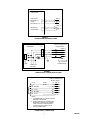
The connections required to connect the V-9923B to
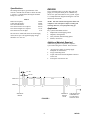
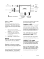
a power supply are shown in Figure 6. Correct
polarity must be observed for the unit to function
properly.
Output Connections
The V-9923B contains a tone generator and isolation
transformer to allow direct hook-up to the paging
system amplifier. The tones are applied to the output
in the coded sequence dialed into the unit. The tones
appear on the TT, (BK/S, pin 29) and the RT (S/BK,
pin 30) leads. If tones are not required as in the case
of using claxton horns, bells, buzzers, lamps, etc. a
contact closure is available. The contact is capable of
handling 1 amp @ 125 Vac or 2 amps @ 30 Vdc.
Higher current requirements should use the contact to
operate a power relay, which would switch the load.
The switched make contact input is the IN lead
(BL/BK, pin 22) and the out lead is the OUT lead
(BK/BL, pin 21).
When the unit is being used by a PABX, the ringing
voltage on the TO and RO leads from the PABX
station releases the code call unit and connects the
PABX trunk (access) to the PABX station (answer).
If the unit is being used with 1A2 key telephones,
when the second party goes off hook on the code call
button, the combined voltage drop across the 10K
Ohm resistors in the A leads releases the code call
unit.
The code call unit is designed so that it will finish
broadcasting a code before returning dial tone and
resetting even if answered in the middle of the code
call sequence.
When the switched output of the V-9923B is used to
operate a DC slave relay, it is necessary to install a
spike suppression diode in parallel with the coil of the
relay. Refer to Figure 7 for the appropriate
connections.
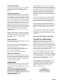
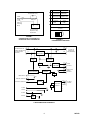
Figure 9 is a simplified schematic illustrating the
main control functions contained in the V-9923B.
TECHNICAL ASSISTANCE
Option Switches
Four option switches are located through the back of
the unit near the amphenol.
When trouble is reported, verify power is being
supplied to the unit and there are no broken
connections. Be sure the amphenol is secure in the
back of the unit and the cable is terminated correctly
on the crossconnect block. Check voltages for proper
polarity on crossconnect block. If a spare unit is
available, continue to troubleshoot by substituting the
spare unit for the suspected defective unit.
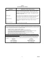
Switch 1 sets either two or three digit operation.
Switch 2 allows or disallows the calling party to hear
the tones as they are sent.
Switch 3 must be left in the ON position.
Switch 4 is for flashing or solid lamp indication on
access (1A2 key systems only).
Refer to Figure 8 for Option Switch Settings.
Assistance in troubleshooting is available from the
factory. When calling, you should have a VOM, a
telephone test set, and several clip leads available and
be calling from the job site. Call (540) 563-2000 and
ask for Technical Support, or call (540) 427-6000 for
Valcom 24-hour Automated Support or visit our
website at http://www.valcom.com.
Two Link Connection
If more than one V-9923B is being used to provide
two link operation, strap EP1 lead from first unit to
EP2 lead of second unit. Strap EP2 lead of first unit
to the EP1 lead of the second unit. A maximum of
two links is all that is possible.
Valcom equipment is not field repairable. Valcom,
Inc. maintains service facilities in Roanoke, VA.
Should repairs be necessary, attach a tag to the unit
clearly stating company name, address, phone
number, contact person, and the nature of the
problem. Send the unit to:
OPERATION
The code call unit is accessed by placing a telephone
or a resistive short across T and R. The unit will
return dial tone to the calling party when it is ready to
accept digits.
NOTE: IN TWO LINK OPERATION, DIAL
TONE WILL BE WITHHELD FROM THE
SECOND LINK UNTIL THE CODE CALL ON
FIRST LINK IS ANSWERED TO PREVENT TWO
CODES BEING BROADCAST
SIMULTANEOUSLY.
Valcom, Inc.
Repair and Return Dept.
5614 Hollins Road
Roanoke, VA 24019-5056
4
947923