1
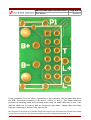
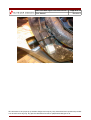
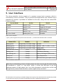
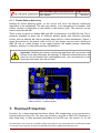
Neri: LED Bike Light Controller-Driver
User Manual
Revision: 1
Created: May 2008
Modified:
Located: D:\My Projects\Neri - My Light\Data, Documentation & Manuals\Neri
Controller Driver\Build Doc, Manual & Product Information\Neri Manual.odt
Neri: LED Bike Light Controller-Driver
User Manual
Page 2 of 12
Revision 1
Table of Contents
1. Introduction........................................................................................3
1.1. Document Revision History..................................................................3
1.2. Terms & Abbreviations.......................................................................3
2. Features & Benefits...............................................................................4
3. Specification........................................................................................5
3.1. Connection Detail.............................................................................5
3.2. Reverse Polarity Protection.................................................................7
4. Suggested Mounting...............................................................................7
4.1. Additional Buttons............................................................................7
5. User Interface......................................................................................9
5.1. Synchronising Multiple Driver-Controllers...............................................10
6. Battery Monitoring..............................................................................10
6.1. Low Battery Warning........................................................................10
6.2. Low Battery Disconnect....................................................................10
6.2.1. Disable Battery Monitoring...........................................................11
7. Thermal Protection..............................................................................11
8. Serial Communications.........................................................................12
This document is the property of Outsider Designs and may be freely distributed and reproduced provided
it is not altered in any way. Any queries should be directed to [email protected].
Neri: LED Bike Light Controller-Driver
User Manual
Page 3 of 12
Revision 1
1. Introduction
The Neri LED bike light driver-controller is intended to provide mountain bike riders and
other enthusiasts with a compact constant current source necessary to optimally drive
high brightness LEDs. The driver is also well suited to car, caravan and boat applications
and can be configured as such.
This document may reference a lamp assembly, which may or may not have been
included with the driver. There are many housing options available for the DIYer and the
user is encouraged to think carefully about what they require, resources available to
them and then search the internet for inspiration and tips.
1.1. Document Revision History
Revision
Date
Draft
May 08
1
Summary of change
Introduction of document & prototype development
September 08 Completed and made available for download
1.2. Terms & Abbreviations
DC
Driver-Controller.
HI
Highest intensity mode.
LED
Light Emitting Diode, indicator or illumination class.
LBW
Low Battery Warning.
LBD
Low Battery Disconnect.
LO3
Highest intensity LO mode level.
LO2
Medium intensity LO mode level.
LO1
Lowest intensity LO mode level.
NTC
Negative Temperature Coefficient.
STANDBY
HB LED is drive off. Short term low power mode.
µC
Micro-controller.
UI
User Interface.
This document is the property of Outsider Designs and may be freely distributed and reproduced provided
it is not altered in any way. Any queries should be directed to [email protected].
Neri: LED Bike Light Controller-Driver
User Manual
Page 4 of 12
Revision 1
2. Features & Benefits
Constant current converter for driving “high brightness” LEDs. Keeps the light
bright and white to the end. Just add LED(s) and battery.
Simple, intuitive single button user interface; instantly toggle between HI & LO
modes without having to go through OFF.
Green and Red status LEDs and piezoelectric sounder provide visual and audible
feedback.
3 step LO mode: Choose the intensity level right for the conditions and maximise
battery life with on-the-fly selectable LO level.
FLASH mode for being seen; will flash at selected LO level.
Compact and lightweight enough to mount on bar or under helmet visor (when
used as a helmet light).
Robust: LED technology means no bulbs to blow. HB LEDs are typically rated for
100,000 hours before reaching 70% of their original output (that's over 11 years of
continuous use). They'll never leave you in the dark.
Integrated battery monitoring provides a low battery warning and protects the
battery from deep discharge1.
Thermal protection: Checks LED temperature and protects against overheating.
Wide supply voltage: 4 – 20Vdc: Can be used with a wide variety of battery
packs2.
MOSFET protection against accidental reverse battery polarity.
Uses standard AA cells (Alkaline3 or rechargeable) which are readily available
almost everywhere.
1
LBW & LBD currently only supports NiMh battery chemistries. Battery monitoring can be disabled.
Minimum voltage depends on LED(s) used.
3
If using alkaline cells, battery monitoring should be disabled to take full advantage of the freedom to deeply discharge the cells;
increasing runtime (how much depends on LED(s) used).
2
This document is the property of Outsider Designs and may be freely distributed and reproduced provided
it is not altered in any way. Any queries should be directed to [email protected].
Neri: LED Bike Light Controller-Driver
User Manual
Page 5 of 12
Revision 1
3. Specification
Description
Value
Units
Vbatt
Battery/Supply voltage1
4 - 20
Volts
ILED
LED drive current
1000
mA
Tamb
Operating ambient temperature2
-40 to +85
°C
>87
%
55 x 17
mm
Conversion efficiency3
Physical dimensions
Table 1: Specification
1
Actual minimum depends on LED(s) being driven and Vbatt. Maximum must not be exceeded.
Applies to DC only. Thermal management of LED and lamp assembly will differ with design, therefore maximum operating
temperature may be lower, governed by the LED(s). Thermal protection should be utilised by fitting a thermistor in the lamp body
(see section 7 - Thermal Protection).
3
Varies with battery voltage.
2
3.1. Connection Detail
Pin
Description
1
Reserved
2
Reserved
3
LED 10KΩ NTC thermistor
4
Reserved
5
Battery positive (+)
6
LED 10KΩ NTC thermistor
7
Battery negative (–)
8
LED positive (+)
9
Reserved
10
LED negative (–)
11
Tx reserved for future
12
Rx reserved for future
Table 2: Electrical Connections
This document is the property of Outsider Designs and may be freely distributed and reproduced provided
it is not altered in any way. Any queries should be directed to [email protected].
Neri: LED Bike Light Controller-Driver
Page 6 of 12
User Manual
Revision 1
Figure 1: Connection detail (viewed from top). Connector itself is optional.
If the connector P1 is not fitted, connection to the controller can be made directly to
the PCB. The battery connects to B+ and B-, LED to L+ and L-. Two larger holes are
provided for securing wires and providing strain relief via small cable ties or lace. Care
must be taken not to twist or pull on connectors and cables. Always take care when
fitting or removing to ensure a long service life.
This document is the property of Outsider Designs and may be freely distributed and reproduced provided
it is not altered in any way. Any queries should be directed to [email protected].
Neri: LED Bike Light Controller-Driver
User Manual
Page 7 of 12
Revision 1
3.2. Reverse Polarity Protection
The driver-controller board includes circuitry on the power input to help protect against
inadvertent incorrect connection of the battery. The maximum voltage limit of 20V
must not be exceeded.
4. Suggested Mounting
The driver-controller was designed from the start to be mounted on the bar near either
the left or right grip. It can also be mounted under a helmet visor (see Figure 2) or
anywhere else where it can be seen easily and reached quickly and comfortably. It is
recommended that the DC is covered and sealed with clear heat-shrink tube to protect
it from water, mud and debris. As an extra step, conformal coating (a varnish type
covering) will provide additional protection.
Use releasable zip-ties, velcro straps, O-rings, rubber bands or other method of choice
to secure the DC in place.
Important: Do not over-tighten any securing straps. Do not excessively flex
the PCB or risk permanent damage.
Tip: Add a strip of foam rubber (adhesive backed foam tape, mouse mat,
door/window weather seal or similar) to the back of the covered and sealed DC to
help reduce mechanical shocks transferring to the PCB/components. This will also help
to keep it in place.
4.1. Additional Buttons
The user may choose to mount the PCB in an enclosure and use their own remote
switch. Additional buttons can be added by placing a momentary push-to-make
(normally open) button in parallel with B1. It can be simply tagged on, or B1 can be
removed. Also see 5.1 Synchronising Multiple Driver-Controllers.
This document is the property of Outsider Designs and may be freely distributed and reproduced provided
it is not altered in any way. Any queries should be directed to [email protected].
Neri: LED Bike Light Controller-Driver
User Manual
Page 8 of 12
Revision 1
Figure 2: A prototype after test ride
This document is the property of Outsider Designs and may be freely distributed and reproduced provided
it is not altered in any way. Any queries should be directed to [email protected].
Neri: LED Bike Light Controller-Driver
Page 9 of 12
User Manual
Revision 1
5. User Interface
The driver-controller circuit consists of a constant current buck converter which is
controlled by a micro-controller. The µC provides the single button user interface and a
piezoelectric sounder is provided for feedback to the user, along with two status LEDs
(Green and Red).
Current Mode
Action
Result
STANDBY
Push B1 (<1s)
HI mode
HI or LO
Push B1 (<1s)
Toggle HI/LO mode
LO
Hold B1
Select LO level†
HI
Hold B1 (~1s)
FLASH mode
HI, LO or FLASH
Double-push (<1s)
STANDBY
Table 3: User Interface
†
Quick cycle through LO level (LO3-LO2-LO1-LO2-LO3...), release when selected mode is reached.
Status LEDs
Sounder
Indicates
Steady green
Single beep on mode change HI mode
Blinking green
Single beep on mode change 3 blinks = LO3, 2 = LO2, 1 = LO1
Flashing green
Single beep on mode change FLASH mode
Red flash every 5 sec
None
STANDBY mode
Flashing red
2 beeps
Low Battery Warning
Fast flashing red
3 beeps
Battery discharged (LBD active)
Steady red
4 beeps
Over-temperature
Steady red
5 beeps
LED thermistor gone open circuit
Table 4: Indicators and alerts
Note: Due to diminishing returns of light output for drive current the HI mode should
be considered a “turbo” or “over-drive” mode. It drives the LED hard to get the
maximum amount of light output, but, for a little decrease in intensity the current can
be significantly reduced and therefore runtime significantly increased.
This document is the property of Outsider Designs and may be freely distributed and reproduced provided
it is not altered in any way. Any queries should be directed to [email protected].
Neri: LED Bike Light Controller-Driver
User Manual
Page 10 of 12
Revision 1
5.1. Synchronising Multiple Driver-Controllers
Multiple modules can be synchronised simply by connecting the button signal lines and
grounds of each module together. If they are sharing a common power source then the
ground is already taken care of. Just connect the inner-most pin of B1 (closest to the
uC) to it's neighbour. All connected buttons will function, controlling all modules.
Superfluous buttons may be removed.
6. Battery Monitoring
6.1. Low Battery Warning
When the battery voltage falls to less than 1 volt per cell for 10 seconds continuously, 2
beeps will be heard and the Status LED will flash red. Normal operation is allowed.
6.2. Low Battery Disconnect
In order to protect the battery from deep discharge, a two-stage LBD scheme is
employed:
1. When the battery volts fall to 0.8 volts per cell for 10 seconds continuously the
controller will drop back to the next lowest power level. This reduces the load on
the battery and allows it to recover slightly to provide additional runtime at the
lower level. This cycle is repeated until the lowest power mode (which is LO1 FLASH is not implemented in LBD) is reached, then stage 2 comes in to effect.
2. When the battery volts again fall to 0.8 volts per cell for 10 seconds continuously,
power to the Emitter is ramped down and the controller will go into STANDBY. 3
beeps will sound shortly before LBD ramps down the lamp (ramps down rather
than suddenly switching off). Once LBD has activated the lamp cannot be repowered by pressing B1 as normal, but can be over-ridden if necessary (see
below).
Note: The amount of time remaining at LBW will vary depending on your battery's
capacity, condition (age) and LED used. You will become familiar with the performance
of your configuration to gauge remaining runtime.
As an example, with eight 2700mAh AA cells and an 8.6W Lamina Atlas LED; HI mode ran
for ~3hrs before LBD stepped down to LO3. On fresh batteries, LO3 would run for 13hrs
before LBD activated and switched to LO2.
This document is the property of Outsider Designs and may be freely distributed and reproduced provided
it is not altered in any way. Any queries should be directed to [email protected].
Neri: LED Bike Light Controller-Driver
User Manual
Page 11 of 12
Revision 1
6.2.1. Disable Battery Monitoring
Holding B1 whilst applying power to the circuit will force the battery monitoring
algorithms to be suppressed. The user may decide, in an emergency for example, that
further runtime is preferable to the health of the battery pack. This function can be
used to override the LBD.
There is also an option to disable LBW and LBD via placement of a 0805 0Ω link. This is
primarily intended to allow use of different battery packs with different discharge
curves, such as alkaline AA cells or perhaps when used in a fixed installation. Figure 3
shows the bottom of the board. Next to the µC two spaces can be found, placing an
0805 0Ω link (or solder bridge) in the upper position will enable battery monitoring
(default), placing it in the lower position will disable it.
Important: Disabling the battery monitoring algorithms will not protect the
battery from deep discharge and damage! If alternative batteries are to be
used; do not mix alkaline and rechargeable cells, only use batteries of the
same type and never mix old and new.
Figure 3: Option link: Top position - battery monitoring
disabled, bottom - enabled (default)
7. Thermal Protection
Provision for a lamp mounted thermistor allows LED temperature to be monitored to
ensure safety and long life. The user may choose to provide a 10KΩ NTC thermistor in
their lamp body, in close proximity (thermally) to the LED core. See section 3.1 for the
This document is the property of Outsider Designs and may be freely distributed and reproduced provided
it is not altered in any way. Any queries should be directed to [email protected].
Neri: LED Bike Light Controller-Driver
User Manual
Page 12 of 12
Revision 1
connection details. The µC will use this to monitor LED temperature and protect against
over-heating if cooling is inadequate.
The µC will check, at power up, to see if the thermistor is fitted; if it is, then thermal
monitoring will begin, if it isn't, thermal monitoring will be suppressed. If the thermistor
is in place at power up and later goes open circuit (e.g. broken wire) the user will be
notified by 5 beeps and a steady red LED.
Note: If no action is taken to fix the open-circuit sensor the fault will be
ignored at next power up and thermal protection cannot operate.
Warning: Without thermal protection the LED(s) and enclosure can get
extremely hot. Many variables affect how hot and how quickly the
temperature will rise. The user is responsible for ensuring no loss or
damage to property or person.
If the lamp assembly reaches ~60°C the controller will indicate that an overtemperature condition exists with a steady red LED, approximately 30 seconds later it
will drop to the next lowest power state accompanied with a single beep. If after a
further 30 seconds the lamp temperature still hasn't dropped, the next lowest power
state will be selected and this cycle will continue until forced into STANDBY. Thermal
throttle-back can be temporarily over-ridden by pushing B1, however it is not
recommended.
8. Serial Communications
Serial communication data lines are brought out to the edge connector for future use.
<end of document>
This document is the property of Outsider Designs and may be freely distributed and reproduced provided
it is not altered in any way. Any queries should be directed to [email protected].