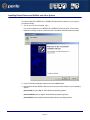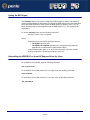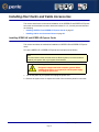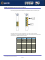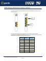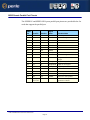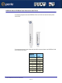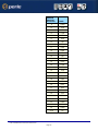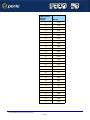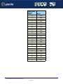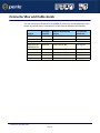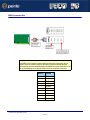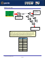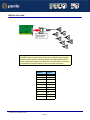
1
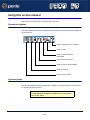
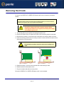
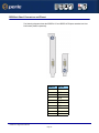
SPEED LE
and
SPEED LE Express
Serial Adapters
User Guide
Part number: 5500174-14
Date: 11 September 2008
Navigating around this manual
Using this on-line manual. See page 5.
Fast Contents. See page 7.
Contents. See page 8.
Index. See page 60.
Page 1
Copyright statement
This document must not be reproduced in any way whatsoever, either printed or
electronically, without the consent of:
Perle Systems Limited
60 Renfrew Drive
Markham,
Ontario,
Canada
L3R 0E1
Perle reserves the right to make changes without further notice, to any products to improve
reliability, function or design.
JETSTREAM, JETSTREAM4000, JETSTREAM8500 and LANSTREAM2000 are trademarks
of Perle Systems Limited.
Microsoft, Windows 2000, XP, Server 2003, Vista, Server 2008, and Internet Explorer are
trademarks of Microsoft Corporation.
Netscape is a trademark of Netscape Communications Corporation.
Perle Systems Limited.
Page 2
FCC Note
The products described in this manual have been found to comply with the limits for a Class
A digital device, pursuant to Part 15 of the FCC rules. These limits are designed to provide
reasonable protection against harmful interference when the equipment is operated in a
commercial environment. This equipment generates, uses and can radiate radio frequency
energy and, if not installed and used in accordance with the instructions in this Guide, may
cause harmful interference to radio communications. Operation of this equipment in a
residential area is likely to cause harmful interference, in which case the user will be required
to correct the interference at his/her own expense.
EN 55022: 1998, Class A Note
Warning: This is a Class A product. In a domestic environment this product may cause radio
interference in which case the user may be required to take adequate measures.
Caution: The products described in this manual are approved for commercial use only.
Page 3
SPEED LE and SPEED LE Express Serial Adapters
User Guide
About this manual
Purpose of this manual
This manual tells you how to install, configure and use the Perle SPEED LE and SPEED LE
Express serial adaptor cards, cabling hardware, associated drivers and utilities.
Who this manual is for
This manual is aimed at users who want to add extra serial ports to their system using
SPEED LE or SPEED LE Express serial adaptor cards. This manual requires a working
knowledge of using personal computers and associated operating systems, as well as
experience in installing host cards.
Warning
Dangerous voltages exist inside computer systems. Before
installing host cards in your system, turn off the power supply
and disconnect the power cord.
Purpose of this manual SPEED LE User Guide
Page 4
Using this on-line manual
The following is a brief guide to using this manual on-line.
Document navigation
This manual features document navigation hypertext buttons in the header area as shown in
the next picture;
Jump to Using this on-line manual
Jump to Index
Jump to Quick Reference
(if included)
Jump to previous location
Jump to front of current chapter
Jump to Contents
Jump to Fast contents
Hypertext jumps
You can also navigate around this manual by clicking on any cross reference or text in blue
for example, Hypertext jumps.
Note
The Fast Contents, Contents and Index entries are all hypertext
jumps into this manual.
Using this on-line manual SPEED LE User Guide
Page 5
Revision history
Date
Part number
Description
December 2005
5500174-10
First issue of the SPEED LE user manual.
March 2007
5500174-11
Added instructions for a new Windows 2000/XP/Server 2003/Vista
installation process. There are now three Windows drivers to support 32-bit,
64-bit x64, and 64-bit Itanium operating systems/processors.
February 2008
5500174-12
Updated guide to support SPEED LE Express cards. Also, a new feature has
been added that allows you to configure the DSR signal to always be on, for
applications that require the DSR signal when the wiring does not support it.
July 2008
5500174-13
Updated guide to support new SPEED LE and SPEED LE Express cards
that support combinations of serial and parallel ports.
September 2008
5500174-14
Added support for Windows Server 2008.
Page 6
SPEED LE and SPEED LE Express Serial Adapters
User Guide
Fast Contents
ABOUT THIS MANUAL ........................................................... 4
REVISION HISTORY ............................................................... 6
FAST CONTENTS .................................................................. 7
CONTENTS ........................................................................... 8
CHAPTER 1 INTRODUCTION .................................................. 11
CHAPTER 2 INSTALLING DRIVERS AND HOST CARDS ............ 14
CHAPTER 3 CABLING INFORMATION ...................................... 31
APPENDIX A: TROUBLESHOOTING ......................................... 53
APPENDIX B: CONTACTING PERLE ....................................... 56
INDEX .................................................................................. 60
Page 7
SPEED LE and SPEED LE Express Serial Adapters
User Guide
Contents
ABOUT THIS MANUAL ............................................................ 4
Purpose of this manual ..................................................................................4
Who this manual is for ...................................................................................4
Using this on-line manual ..............................................................................5
Document navigation ................................................................................5
Hypertext jumps ........................................................................................5
REVISION HISTORY ................................................................ 6
FAST CONTENTS ................................................................... 7
CONTENTS ............................................................................ 8
CHAPTER 1 INTRODUCTION ................................................... 11
About the SPEED LE Serial Adaptor cards ...............................................12
Connection Accessories ...............................................................................13
CHAPTER 2 INSTALLING DRIVERS AND HOST CARDS ............. 14
Before You Start ..............................................................................................15
Downloading Drivers From the Perle Website ..........................................16
Installing under Windows 2000/XP/Server 2003/Vista/Server 2008 .......17
General setup procedure for Windows 2000/XP/Server 2003/Vista/
Server 2008 ..............................................................................................17
Installing Device Drivers and Utilities onto Your System ..........................18
Adding Additional Cards and/or Updating Drivers ....................................20
Configuring Serial Ports ............................................................................21
Page 8
Installing under Linux .....................................................................................23
General Installation Procedure for Linux...................................................23
Installing Drivers onto Your System ..........................................................23
Install from Source RPM ................................................................................ 24
Install from Tar File Driver Version 3.4.x or Below ......................................... 24
Install from Tar File Driver Version 3.5.x or Higher ........................................ 25
Creating Devices for the Attached Ports ...................................................25
Setting the DSR Signal .............................................................................26
Uninstalling the SPEED LE or Speed LE Express Driver for Linux ..........26
Installing Host Cards and Cable Accessories ...........................................27
Installing SPEED LE and SPEED LE Express Cards ...............................27
Installing Cables and Connector Boxes ....................................................28
Installing cables on SPEED1 LE, SPEED2 LE, and SPEED4 LE cards ....... 28
Installing Fan-out Cables and Connector Boxes on SPEED4 LE HD and
SPEED8 LE HD Cards ......................................................................... 29
Removing Host Cards ....................................................................................30
CHAPTER 3 CABLING INFORMATION....................................... 31
Definitions of Signals and Direction ............................................................32
DB9 Back Panel Connectors and Pinout ..................................................33
Host Card Back Panel Connectors and Pinouts .......................................34
SPEED LE RJ45 Back Panel Connectors and Pinout ..............................35
SPEED LE Express RJ45 Back Panel Connectors and Pinout ................36
DB25 Femaie Parallel Port Pinouts ..........................................................37
VHDCI-68 Ultra SCSI Back Panel Connectors and Pinout.......................38
Connector Box and Cable Guide .................................................................43
Connector Box and Cable Pinouts ..............................................................44
RJ45 10-pin to DB25 Converter................................................................45
RJ45 10-pin to DB9 Converter..................................................................46
RJ45 Connector Box.................................................................................47
DB25 Connector Box ................................................................................48
DB9 Connector Box ..................................................................................49
DB25 Fan-Out Cable ................................................................................50
DB9 Fan-Out Cable ..................................................................................51
Low Profile Bracket Conversion ..................................................................52
Page 9
APPENDIX A: TROUBLESHOOTING.......................................... 53
Windows 2000/XP/Server 2003/Vista/Server 2008 ....................................54
General Troubleshooting under Windows 2000/XP/Server 2003/Vista/
Server 2008 ..............................................................................................55
Windows Error Messages .........................................................................55
APPENDIX B: CONTACTING PERLE ........................................ 56
Making a technical support query ...............................................................56
Who to contact ..........................................................................................56
Information needed when making a query................................................57
Making a support query via the Perle web page.......................................58
Repair procedure ............................................................................................58
Feedback about this manual ........................................................................58
Perle support centres worldwide .................................................................59
INDEX ................................................................................... 60
Page 10
Chapter 1 Introduction
You need to read
this chapter if you
want to...
You need to read this chapter if you want an introduction to the SPEED LE or SPEED LE
Express serial adaptor cards, driver software, and utilities.
This chapter provides introductory information about the Perle SPEED LE and SPEED LE
Express serial adaptor cards, driver software, and configuration utilities.
This chapter includes the following sections;
•
About the SPEED LE Serial Adaptor cards on page 12
•
Connection Accessories on page 13
Chapter 1 Introduction
Page 11
About the SPEED LE Serial Adaptor cards
The SPEED LE and SPEED LE Express Serial Adaptor cards are multi-port cards which
provide extra serial ports for EIA-232, peripherals. These cards plug into your PC servers
and provide 1, 2, 4, or 8 high speed ports suitable for remote access, data collection, point of
sale, or any other EIA-232 applications.
You use the SPEED LE and SPEED LE Express serial adaptor cards when you want a
robust entry level solution for the small office or point of sale applications. Typically you use
SPEED LE and SPEED LE Express serial adaptor cards because you want to add extra
serial ports to an existing computer system rather than replacing it with the considerable cost
that entails. Higher data rates and ESD protection in the SPEED LE and SPEED LE Express
serial adaptor cards make it suitable for any modem or ISDN TA application.
Note
To use the SPEED LE and SPEED LE Express serial adaptor cards, you must first install
the drivers supplied with the card and then configure each card as required prior to
mechanical installation. The installation procedure varies for different operating systems.
Please read Before You Start on page 15 in Chapter 2 Installing drivers and host cards before
commencing installation.
Chapter 1 Introduction
Page 12
Connection Accessories
The connector box or cable required for the SPEED LE products you are using depends on
the number of ports and product type. For details see Chapter 3 Cabling Information.
Chapter 1 Introduction
Page 13
Chapter 2 Installing Drivers and Host Cards
You need to read
this chapter if you
want to...
You need to read this chapter if you want to install SPEED LE or SPEED LE Express serial
adaptor cards, associated hardware, and software.
This chapter provides information about installing and configuring SPEED LE and SPEED LE
Express serial adaptor cards.
Note
The procedure for installing and configuring SPEED LE or SPEED LE Express serial
adaptor cards varies for different operating systems. Please read Before You Start on
page 15 before commencing installation.
This chapter includes the following sections;
•
Before You Start on page 15
•
Downloading Drivers From the Perle Website on page 16
•
Installing under Windows 2000/XP/Server 2003/Vista/Server 2008 on page 17
•
Installing under Linux on page 23
•
Installing Host Cards and Cable Accessories on page 27
•
Removing Host Cards on page 30
Chapter 2 Installing Drivers and Host Cards
Page 14
Before You Start
Before you install your SPEED LE or SPEED LE Express host cards and software, note that
the procedure for installing and configuring SPEED LE or SPEED LE Express serial adaptor
cards varies for different operating systems.
To install under a particular operating system, please refer to one of the operating system
specific installation procedures listed below;
•
Installing under Windows 2000/XP/Server 2003/Vista/Server 2008 on page 17
•
Installing under Linux on page 23
Chapter 2 Installing Drivers and Host Cards
Page 15
Downloading Drivers From the Perle Website
You can install the SPEED LE or SPEED LE Express driver and utility software from the
Perle website. To do this proceed as follows;
1. On your PC, start the Internet browser you want to use.
2. Within your Internet browser window, select the software directory using the following
URL;
http://www.perle.com/downloads
Note
In the event of any problems contact your System Administrator or
Internet Service provider for assistance.
3. Select the MultiPort Serial Cards option.
4. Select Speed LE.
5. Select the operating system that the SPEED LE or SPEED LE Express driver will be
running on.
6. Download the zip file in this directory to a suitable location on your PC for example, /tmp.
7. Uncompress the files using a suitable utility.
8. You can now install the driver software using the correct procedure for your operating
system. See Before You Start on page 15.
Chapter 2 Installing Drivers and Host Cards
Page 16
Installing under Windows 2000/XP/Server 2003/Vista/
Server 2008
This section describes how to install the SPEED LE or SPEED LE Express driver software
under Microsoft Windows 2000, XP, Server 2003, Vista, or Server 2008.
This section includes the following;
•
General setup procedure for Windows 2000/XP/Server 2003/Vista/Server 2008 on
page 17
•
Installing Device Drivers and Utilities onto Your System on page 18
•
Adding Additional Cards and/or Updating Drivers on page 20
•
Configuring Serial Ports on page 21.
General setup procedure for Windows 2000/XP/Server 2003/Vista/Server 2008
The general procedure for installing SPEED LE or SPEED LE Express cards under the
Windows 2000, XP, Server 2003, Vista, or Server 2008 operating systems is as follows;
1. Install any SPEED LE or SPEED LE Express cards and cables or connector boxes you
require into your system. See Installing Host Cards and Cable Accessories on
page 27.
2. Install the SPEED LE or SPEED LE Express device driver software. See Installing
Device Drivers and Utilities onto Your System on page 18.
3. If you add new SPEED LE or SPEED LE Express cards, you should run Update Driver to
make sure the new cards have the latest driver. See Adding Additional Cards and/or
Updating Drivers on page 20.
4. If required, remove any host cards you want from your system. See Removing Host
Cards on page 30.
5. Using the Windows Device Manager, configure the serial ports you have added to the
system. See Configuring Serial Ports on page 21.
Chapter 2 Installing Drivers and Host Cards
Page 17
Installing Device Drivers and Utilities onto Your System
To install or enable the SPEED LE or SPEED LE Express device drivers on your system
proceed as follows:
1. Turn on your PC and if required, log in.
If you have installed any new SPEED LE or SPEED LE Express cards, a Found New
Hardware message is shown, followed by the Found New Hardware wizard as shown.
2. In the Found New Hardware wizard click on the Cancel button.
3. Download the lastest SPEED LE driver zip file from the Perle website for your operating
system:
pserial-x86V<version>.zip for 32-bit Windows operating systems.
pserial-amd64V<version>.zip for 64-bit Windows operating systems.
pserial-ia64V<version>.zip for 64-bit Windows Itanium operating systems.
Chapter 2 Installing Drivers and Host Cards
Page 18
4. Unzip the driver zip file to a local directory. We recommend that you use the
pserial-setup-<arch>.exe file, which will launch the installation wizard, to install the
SPEED LE driver.
5. Double-click the pserial-setup-<arch>.exe installation executable and follow the
installation wizard steps:
Chapter 2 Installing Drivers and Host Cards
Page 19
6. During the installation, you may get a Windows Logo message. Click Continue Anyway
when these appear.
Note
If you are installing an unsigned driver, you may have to click through the Found New
Hardware wizard for every SPEED LE or SPEED LE Express port on your system.
Your SPEED LE or SPEED LE Express driver installation is now finished.
Adding Additional Cards and/or Updating Drivers
Whenever you add any additional SPEED LE or SPEED LE Express hardware to your
system, Windows might install the latest digitally signed driver in its database (depending on
your Windows operating system and settings). To ensure you have the latest driver installed
after you add new hardware, you can either:
•
Click Start > All Programs > Perle > Perle-Serial > Update Driver
or
•
Reinstall the drivers as described in Installing Device Drivers and Utilities onto Your
System on page 18.
Chapter 2 Installing Drivers and Host Cards
Page 20
Configuring Serial Ports
To configure SPEED LE or SPEED LE Express serial ports under Windows 2000, XP,
Server 2003, Vista, or Server 2008 proceed as follows:
1. In the Windows desktop, click on the Start button and select Settings > Control Panel
The control panel window is now displayed.
2. In the Control Panel window, click on the System icon.
The System Properties tabbed window is now displayed.
3. In the System Properties window, click on the Hardware tab.
The hardware page is now displayed.
4. In the Hardware page, click on the Device Manager Button.
The Device Manager window is now displayed.
Chapter 2 Installing Drivers and Host Cards
Page 21
5. In the Device Manager window, click on the Multiport serial adapters icon to display the
currently installed devices.
6. In the Device Manager window, double click on the device whose properties you want to
view or change
The device Properties tabbed window is now displayed.
7. In the device Properties window, click on the Port Settings tab to display the Port
Settings page.
8. In the Port Settings page, set the Port Number, Baud Rate, and any other configuration
parameters you require.
DSR Always On—This feature is used for systems where the wiring does not support the
DSR signal but the Host application still requires that the DSR be active. When the DSR
Always On option is enabled, the driver will always report to the application that the DSR
signal is "on".
Chapter 2 Installing Drivers and Host Cards
Page 22
Installing under Linux
This section tells you how to install host cards, software drivers, and utilities under the Linux
operating system and includes the following:
•
General Installation Procedure for Linux on page 23
•
Installing Drivers onto Your System on page 23
•
Creating Devices for the Attached Ports on page 25
General Installation Procedure for Linux
The general procedure for installing and configuring host cards, driver software and
associated utilities for the Linux operating system is as follows:
1. Install any SPEED LE or SPEED LE Express cards you require into your system. See
Installing Host Cards and Cable Accessories on page 27.
2. Install the SPEED LE Linux drivers onto your system using the procedures described in
Installing Drivers onto Your System on page 23.
3. Create devices for the required ports using the procedures detailed in Creating Devices
for the Attached Ports on page 25.
Your system can now use the SPEED LE serial adaptor cards you have installed.
Installing Drivers onto Your System
SPEED LE or SPEED LE Express cards installed on Linux machines use the perle-serial
driver for Linux. The driver supports the Linux kernel versions 2.4 and 2.6. The kernel header
files are needed for kernel and 2.4. For the 2.6 kernel, a configuration kernel source tree and
a set of makefile rules describing how the modules are built is required.
The driver is supplied in both source RPM package format and a compressed tar file. The
procedure for installation of each format is described in the following sections.
Chapter 2 Installing Drivers and Host Cards
Page 23
Install from Source RPM
1. Log in to the LINUX system as root user.
Notes:
The <packages directory> path name in the following instructions will be different
depending on the LINUX distribution you have installed. ( i.e. Redhat will have a
“redhat” directory; Suse will have a “packages” directory)
The <rpm build command> will change depending on the version of the RPM utilities
installed. For newer versions (i.e. 4.2) , the <rpm build command> is “rpmbuild”. For
older versions use “rpm”.
2. At the LINUX prompt, copy the supplied perle-serial-<version>-<release>.src.rpm file
onto your system in the /tmp directory.
3. Install the source rpm by typing the following command:
rpm –ivh perle-serial-<version>-<release>.src.rpm
4. Build the binary RPM package for your system by entering the following commands:
cd /usr/src/<packages directory>/SPECS
<rpm build command> -bb perle-serial-<version>.spec
5. Install the binary RPM which was just created. Enter the following commands:
cd /usr/src/<packages directory>/RPMS/<arch>
rpm –ivh perle-serial-<version>-<release>.<arch>.rpm
The <arch> value is the architecture of your LINUX machine such as “i386” or “alpha”.
Install from Tar File Driver Version 3.4.x or Below
1. Log in to the LINUX system as root user.
2. At the LINUX prompt, copy the supplied perle-serial .tgz file onto your system in the /tmp
directory.
3. Unpack the file using the command:
tar –xzvf perle-serial-<version>-<release>.tgz
4. Build and install the perle-serial software by entering the following commands:
cd /tmp/perle-serial-<version>-<release>
./tar_install.sh
Chapter 2 Installing Drivers and Host Cards
Page 24
Install from Tar File Driver Version 3.5.x or Higher
1. Log in to the LINUX system as root user.
2. At the LINUX prompt, copy the supplied perle-serial .tgz file onto your system in the /tmp
directory.
3. Unpack the file using the command:
tar –xzvf perle-serial-<version>-<release>.tgz
4. In the directory run:
make
Note: If the parallel port driver has been installed, then the system will need to be rebooted to
complete the uninstall proces.
Creating Devices for the Attached Ports
After the SPEED LE or SPEED LE Express cards and the new driver have been installed,
terminal devices will need to be created for the added ports. This can be done be using the
ps_addports utility.
To use the ps_addports script, enter the following command:
ps_addports m n
where:
m is the first port device (starting at 0)
n is the last port device to add.
The port devices will be created in the /dev directory and will have the following format:
where nn is the 2 digit port number.
The perle-serial driver has been installed so that it will automatically be loaded the first time a
SPEED LE or SPEED LE Express device is used. However, if more than one SPEED LE or
SPEED LE Express card was installed in the Linux machine, then the driver can be manually
loaded to determine which terminal device numbers have been assigned to each card.
To load the driver, enter the command:
modprobe perle-serial
Review the messages in the file /var/log/messages.
Once the port devices have been created, they may be used as standard LINUX serial TTYs.
Chapter 2 Installing Drivers and Host Cards
Page 25
Setting the DSR Signal
The setultrap utility can be used to configure the DSR Always On option. This feature is
used for systems where the wiring does not support the DSR signal but the Host application
still requires that the DSR be active. When the DSR Always On option to set to "on," the
driver will always report to the application that the DSR signal is "on". The syntax for the
command is:
To use the setultrap utility, enter the following command:
setultrap -f device name -r on|off|list
where:
-f specifies the port the action should be taken on.
•
/dev/ttyPS1 specifies port 1
•
/dev/ttyPS1,/dev/ttyPS64 specifies port 1 through port 64 (ranges are
separated by a comma with no space between them)
-r sets DSRAlwaysOn option on or off for serial devices(s). Use list to see the
existing configuration. By default this option is set to off.
Uninstalling the SPEED LE or Speed LE Express Driver for Linux
To uninstall the driver (RPM), enter the following command:
rpm -e perle-serial
To uninstall the driver (TAR) version 3.5.x or higher, enter the following command:
make uninstall
To uninstall the driver (TAR) version 3.4.x or lower, enter the following command:
./tar_uninstall.sh
Chapter 2 Installing Drivers and Host Cards
Page 26
Installing Host Cards and Cable Accessories
This section describes the mechanical installation of the SPEED LE and SPEED LE Express
host cards and associated connector boxes and cables for 1,2, 4, and 8 ports and includes
the following;
•
Installing SPEED LE and SPEED LE Express Cards on page 27
•
Installing Cables and Connector Boxes on page 28
Installing SPEED LE and SPEED LE Express Cards
This section describes the mechanical installation of SPEED LE and SPEED LE Express
cards.
To install a SPEED LE or SPEED LE Express host card proceed as follows;
Note
The exact location of host card slots varies for different systems, for exact mechanical
details of your system, refer to your system documentation.
Warning
Dangerous voltages exist inside computer systems. Before
installing host cards in your system, turn off the power supply
and unplug the power cord.
1. Turn off the power to your system and unplug the power cord.
2. Remove the system cover to expose the inside of the connector panel for host cards.
Chapter 2 Installing Drivers and Host Cards
Page 27
3. Insert the SPEED LE or SPEED LE Express card you want to install into a vacant host
PCI card slot and secure in place as shown in the next picture.
Caution
Full anti-static precautions should be taken when handling host
cards.
4. Repeat step 3. until you have installed all the SPEED LE or SPEED LE Express cards
you want.
5. Replace and secure the system cover.
Installation of SPEED LE or SPEED LE Express cards is now complete.
Installing Cables and Connector Boxes
This section describes the mechanical installation of cables and connector boxes to the
SPEED LE and SPEED LE Express host cards for 1, 2, 4, and 8 ports and includes the
following;
•
Installing cables on SPEED1 LE, SPEED2 LE, and SPEED4 LE cards on page 28.
•
Installing Fan-out Cables and Connector Boxes on SPEED4 LE HD and SPEED8 LE
HD Cards on page 29.
For information on available connectors and their pinouts and cabling, see Chapter 3
Cabling Information.
Installing cables on SPEED1 LE, SPEED2 LE, and SPEED4 LE cards
The SPEED1 LE has a D89M connector on the back panel.
The SPEED2 LE and SPEED4 LE each have RJ45 connectors on the back panel. There is
one for each serial port and they are labelled 1 to 4.
Chapter 2 Installing Drivers and Host Cards
Page 28
Installing Fan-out Cables and Connector Boxes on SPEED4 LE HD and SPEED8 LE HD Cards
SPEED4 LE HD and SPEED8 LE HD cards have a single VHDCI-68 connector on the
back panel. It provides the signals for 4 or 8 serial ports.
A fan-out cable or connector box with the proper individual connectors can be plugged into
the card to provide the desired interface. The port numbers will be identified on the interface
connectors or connector box.
Note
The SPEED LE fan-out cables and connector box cable need to be secured
or supported in case of sudden contact or excessive weight on the cables.
Please ensure that adequate caution is taken to avoid possible damage to
the SPEED LE card or Host system. This can be accomplished by securing
the cable(s) to a rack or to the back of the server as shown below:
Chapter 2 Installing Drivers and Host Cards
Page 29
Removing Host Cards
To remove any SPEED LE or SPEED LE Express card from your system, proceed as
follows;
Note
The exact location of host card slots varies for different systems, for exact mechanical
details of your system, refer to your system documentation.
Warning
Dangerous voltages exist inside computer systems. Before
removing host cards from your system, turn off the power supply
and unplug the power cord.
1. Turn off the power to your system and unplug the power cord.
2. Remove the system cover to expose the inside of the connector panel for host cards.
3. Disconnect any cables or connector boxes connected to the card you want to remove.
4. Undo the securing screw for the host card you want to remove then lift the card out of its
slot as shown in the next picture.
Caution
Full anti-static precautions should be taken when handling host
cards.
5. Repeat from step 3. until you have removed all the host cards you want.
6. Replace and secure the system cover.
7. Plug in the mains lead and turn on the power.
Removal of SPEED LE or SPEED LE Express card is now complete.
Chapter 2 Installing Drivers and Host Cards
Page 30
Chapter 3 Cabling Information
You need to read
this chapter if you
want to...
You need to read this chapter if you want cabling information for the SPEED LE and SPEED
LE Express serial adaptor cards.
This chapter provides cabling and connector pinout information for the SPEED LE and
SPEED LE Express serial adaptor cards. Included are details of standard cables for use with
SPEED LE and SPEED LE Express products available from Perle.
This chapter includes the following sections:
•
Definitions of Signals and Direction on page 32
•
Host Card Back Panel Connectors and Pinouts on page 34
•
Connector Box and Cable Guide on page 43
•
Connector Box and Cable Pinouts on page 44
•
Low Profile Bracket Conversion on page 52
Page 31
Definitions of Signals and Direction
EIA-232
Direction
Description
RI
In
Ring Indicator
DCD
In
Data Carrier Detect
RTS
Out
Request To Send
DSR
In
Data Set Ready
TXD
Out
Transmit Data
RXD
In
Receive Data
S-GND
Signal Ground
CTS
In
Clear to Send
DTR
Out
Data Terminal Ready
C-GND
Chassis Ground
Definitions of Signals and Direction
Page 32
DB9 Back Panel Connectors and Pinout
The following diagram shows the SPEED1 LE and SPEED LE Express standard and Low
Profile back panels respectively.
DB9M pin
EIA-232
1
DCD
2
RXD
3
TXD
4
DTR
5
S-GND
6
DSR
7
RTS
8
CTS
9
RI
10
C-GND
Definitions of Signals and Direction
Page 33
Host Card Back Panel Connectors and Pinouts
This section contains diagrams and pinout information for the SPEED LE and SPEED LE
Express host card back panel connectors contains the following;
DB9 Back Panel Connectors and Pinout on page 33
SPEED LE RJ45 Back Panel Connectors and Pinout on page 35
SPEED LE Express RJ45 Back Panel Connectors and Pinout on page 36
VHDCI-68 Ultra SCSI Back Panel Connectors and Pinout on page 38
Host Card Back Panel Connectors and Pinouts
Page 34
SPEED LE RJ45 Back Panel Connectors and Pinout
The following diagram shows the SPEED2 LE and SPEED4 LE RJ-45 cards back panel.
The RJ45 connector has a 10-pin configuration. If you require an 8-pin connector
configuration, use the pinouts in the RJ45 8-pin column. The connector pinout for each RJ45
socket fitted to the SPEED LE cards is as follows;
RJ45 10-pin
EIA-232
DIRECTION
RJ45 8-pin
1
RI
IN
N/A
2
DCD
IN
1
3
DTR
OUT
2
4
DSR
IN
3
5
GND
6
TXD
OUT
5
7
RXD
IN
6
8
RTS
OUT
7
9
CTS
IN
8
10
Shell
4
N/A
C-GND
Host Card Back Panel Connectors and Pinouts
Page 35
Shell
SPEED LE Express RJ45 Back Panel Connectors and Pinout
The following diagram shows the SPEED2 LE Express and SPEED4 LE Express RJ-45
cards back panel.
The RJ45 connector has a 10-pin configuration. If you require an 8-pin connector
configuration, use the pinouts in the RJ45 8-pin column. The connector pinout for each RJ45
socket fitted to the SPEED LE Express cards is as follows;
RJ45 10-pin
EIA-232
RJ45 8-pin
1
RI
N/A
2
DCD
1
3
RTS
2
4
DSR
3
5
TXD
4
6
RXD
5
7
S-GND
6
8
CTS
7
9
DTR
8
10
N/A
Shell
C-GND
Host Card Back Panel Connectors and Pinouts
Page 36
Shell
DB25 Femaie Parallel Port Pinouts
The SPEED LE and SPEED LE Express parallel port pinouts are provided below for
cards that support the parallel port.
DB25
Pin
Cent Pin
Direction
Signal
Name
Function Notes
1
1
out
-Strobe
Set Low p1ulse >0.5 us to send
2
2
out
Data 0
Set to least significant data
3
3
out
Data 1
4
4
out
Data 2
5
5
out
Data 3
6
6
out
Data 4
7
7
out
Data 5
8
8
out
Data 6
9
9
out
Data 7
Set to most significant data
10
10
in
-Ack
IRQ; Low Pulse ~ 5 uS, after
accept
11
11
in
+Busy
High for Busy/Offline/Error
12
12
in
+PaperEnd
High for out of paper
13
13
in
+SelectIn
High for printer selected
14
14
out
-AutoFd
Set Low to autofeed one line
15
32
in
-Error
Low for Error/Offline/PaperEnd
16
31
out
-Init
Set Low pulse > 50uS to init
17
36
out
-Select
Set Low to select printer
18-25
19-30,
33,17,16
----
Ground
Do not connect any of these
grounds to a shield
Host Card Back Panel Connectors and Pinouts
Page 37
VHDCI-68 Ultra SCSI Back Panel Connectors and Pinout
The following diagram shows the SPEED4 LE HD Low Profile and standard back panels
respectively.
The connector pinout for each VHDCI-68 Ultra SCSI connector fitted to the SPEED4 LE HD
Low Profile are as follows:
VHDCI-68
Ultra SCSI
Pin Number
EIA-232
1
RXD4
2
CTS4
3
RI4
4
RTS4
5
DCD4
6
DTR4
7
DSR4
8
TXD4
Host Card Back Panel Connectors and Pinouts
Page 38
VHDCI-68
Ultra SCSI
Pin Number
EIA-232
9
S-GND
10
TXD3
11
DSR3
12
DTR3
13
DCD3
14
RTS3
15
RI3
16
CTS3
17
RXD3
18
RXD2
19
CTS2
20
RI2
21
RTS2
22
DCD2
23
DTR2
24
DSR2
25
TXD2
26
S-GND
27
TXD1
28
DSR1
29
DTR1
30
DCD1
31
RTS1
32
RI1
33
CTS1
34
RXD1
35-42
NC
43
S-GND
44-59
NC
60
S-GND
61-68
NC
Host Card Back Panel Connectors and Pinouts
Page 39
The following diagram shows the SPEED8 LE HD standard and Low profile back panels
respectively
The connector pinout for each VHDCI-68 Ultra SCSI connector fitted to the SPEED8 LE HD,
Low profile are as follows;
Ports 1-8 of VHDCI-68 Connector for SPEED8 LE HD adapter cards
VHDCI-68 Ultra
SCSI Pin
Number
EIA-232
1
RXD7
2
CTS7
3
RI7
4
RTS7
5
DCD7
6
DTR7
7
DSR7
8
TXD7
9
S-GND
10
TXD5
11
DSR5
12
DTR5
Host Card Back Panel Connectors and Pinouts
Page 40
VHDCI-68 Ultra
SCSI Pin
Number
EIA-232
13
DCD5
14
RTS5
15
RI5
16
CTS5
17
RXD5
18
RXD3
19
CTS3
20
RI3
21
RTS3
22
DCD3
23
DTR3
24
DSR3
25
TXD3
26
S-GND
27
TXD1
28
DSR1
29
DTR1
30
DCD1
31
RTS1
32
RI1
33
CTS1
34
RXD1
35
RXD8
36
CTS8
37
RI8
38
RTS8
39
DCD8
40
DTR8
41
DSR8
42
TXD8
43
S-GND
Host Card Back Panel Connectors and Pinouts
Page 41
VHDCI-68 Ultra
SCSI Pin
Number
EIA-232
44
TXD6
45
DSR6
46
DTR6
47
DCD6
48
RTS6
49
RI6
50
CTS6
51
RXD6
52
RXD4
53
CTS4
54
RI4
55
RTS4
56
DCD4
57
DTR4
58
DSR4
59
TXD4
60
S-GND
61
TXD2
62
DSR2
63
DTR2
64
DCD2
65
RTS2
66
RI2
67
CTS2
68
RXD2
Host Card Back Panel Connectors and Pinouts
Page 42
Connector Box and Cable Guide
The connector pinout information for the SPEED LE product you are using depends on the
number of ports and type of connector box or cable used as detailed in the next table;
Product
Card edge
connector
Cable or connector box
options
For connector
pinouts see...
SPEED LE
RJ45 10-pin
RJ45 - DB25M Converter
See page 45
RJ45 - DB9M Converter
See page 46
RJ45 Connector Box
See page 47
DB25M Connector Box
See page 48
DB9M Connector Box
See page 49
DB25M Fan-out Cable
See page 50
DB9M Fan-out Cable
See page 51
SPEED4 LE HD
VHDCI-68
SPEED8 LE HD
Connector Box and Cable Guide
Page 43
Connector Box and Cable Pinouts
This section contains pinout information for the SPEED LE product range connector box and
cable accessories and contains the following;
•
RJ45 10-pin to DB25 Converter on page 45
•
RJ45 10-pin to DB9 Converter on page 46
•
RJ45 Connector Box on page 47
•
DB25 Connector Box on page 48
•
DB9 Connector Box on page 49
•
DB25 Fan-Out Cable on page 50
•
DB9 Fan-Out Cable on page 51
Note
For details of which cables to use with which product, see Connector Box and Cable
Guide on page 43.
Connector Box and Cable Pinouts
Page 44
RJ45 10-pin to DB25 Converter
RJ45 pin
DB25 Pin
EIA-232
DIRECTION
1
22
RI
IN
2
8
DCD
IN
3
20
DTR
OUT
4
6
DSR
IN
5
7
GND
6
2
TXD
OUT
7
3
RxD
IN
8
4
RTS
OUT
9
5
CTS
IN
10
N/C
1 & Shell
1 & Shell
C-GND
Connector Box and Cable Pinouts
Page 45
RJ45 10-pin to DB9 Converter
RJ45 pin
DB9 Pin
EIA-232
DIRECTION
1
9
RI
IN
2
1
DCD
IN
3
4
DTR
OUT
4
6
DSR
IN
5
5
GND
6
3
TXD
OUT
7
2
RXD
IN
8
7
RTS
OUT
9
8
CTS
IN
10
N/C
Shell
Shell
C-GND
Connector Box and Cable Pinouts
Page 46
RJ45 Connector Box
Connect peripheral
cable here via RJ45
RJ45 connector block
Push fit onto card
edge connector
Note
The SPEED LE connector box cable needs to be secured or supported in case of
sudden contact or excessive weight on the cables. Please ensure that adequate
caution is taken to avoid possible damage to the SPEED LE card or Host system. This
can be accomplished by securing the cable to a rack or to the back of the server.
RJ45 10-pin
RJ45 8-pin
EIA-232
1
N/A
RI
2
1
DCD
3
2
RTS
4
3
DSR
5
4
TXD
6
5
RXD
7
6
S-GND
8
7
CTS
9
8
DTR
10
N/A
NC
Shell
Shell
C-GND
Connector Box and Cable Pinouts
Page 47
DB25 Connector Box
Note
The SPEED LE connector box cable needs to be secured or supported in case of
sudden contact or excessive weight on the cables. Please ensure that adequate
caution is taken to avoid possible damage to the SPEED LE card or Host system. This
can be accomplished by securing the cable to a rack or to the back of the server.
DB25 Pin
EIA-232
1 & Shell
C-GND
2
TXD
3
RXD
4
RTS
5
CTS
6
DSR
7
S-GND
8
DCD
20
DTR
22
RI
Connector Box and Cable Pinouts
Page 48
DB9 Connector Box
Note
The SPEED LE connector box cable needs to be secured or supported in case of
sudden contact or excessive weight on the cables. Please ensure that adequate
caution is taken to avoid possible damage to the SPEED LE card or Host system. This
can be accomplished by securing the cable to a rack or to the back of the server.
DB9 Pin
EIA-232
1
DCD
2
RXD
3
TXD
4
DTR
5
S-GND
6
DSR
7
RTS
8
CTS
9
RI
Shell
C-GND
Connector Box and Cable Pinouts
Page 49
DB25 Fan-Out Cable
Port numbers
labelled on DB25
connectors
Push fit onto card
edge connector
Connect peripheral cable
here
Note
The SPEED LE fan-out cables need to be secured or supported in case of sudden
contact or excessive weight on the cables. Please ensure that adequate caution is
taken to avoid possible damage to the SPEED LE card or Host system. This can be
accomplished by securing the cables to a rack or to the back of the server.
DB25 Pin
EIA-232
1 & Shell
C-GND
2
TXD
3
RXD
4
RTS
5
CTS
6
DSR
7
S-GND
8
DCD
20
DTR
22
RI
Connector Box and Cable Pinouts
Page 50
DB9 Fan-Out Cable
Note
The SPEED LE fan-out cables need to be secured or supported in case of sudden
contact or excessive weight on the cables. Please ensure that adequate caution is
taken to avoid possible damage to the SPEED LE card or Host system. This can be
accomplished by securing the cables to a rack or to the back of the server.
DB9 Pin
EIA-232
1
DCD
2
RXD
3
TXD
4
DTR
5
S-GND
6
DSR
7
RTS
8
CTS
9
RI
Shell
C-GND
Connector Box and Cable Pinouts
Page 51
Low Profile Bracket Conversion
The SPEED LE and SPEED LE Express cards come fitted with standard brackets. Additional
low profile brackets are included with your SPEED LE and SPEED LE Express cards to
accomodate low profile servers. This section describes how to convert your SPEED LE and
SPEED LE Express cards from standard to low profile brackets.
To convert a standard profile bracket to a low profile bracket(s) and install it, do the following:
1. Unscrew the screwlocks around each parallel/serial connector. Remove the standard
profile bracket.
Speed LE 1P and 1S1P models only
Gently remove the serial/parallel connector(s) from the standard bracket and
unscrew the bracket from the serial card. You will see two screws that need to be
removed at the top and the bottom of the card near the bracket.
2. For all models except Speed LE 1P and 1S1P, attach the serial low profile bracket and
secure with the screwlocks around the serial connector.
Speed LE 1P and 1S1P models only
1. Attach the low profile bracket with screws to the serial card.
Align the serial card on top of the low profile bracket mounting tabs and then
insert screws into the serial card holes (bracket mounting tabs must be under the
serial card).
2. Secure the low profile bracket with the screwlocks around the serial/parallel
connector.
3. Insert the remaining serial/parallel connectors into their appropriate low profile bracket(s)
and secure to the bracket(s) with the screwlocks around the serial/parallel connector.
4. Verify that all the serial/parallel connectors are connected to the serial card. The ribbon
cables have a notch in the connector that will allow them to be inserted into the serial card
in only the proper way.
5. Power off the server and disconnect the power cord from the back of the server that you
are going to install the serial card into.
6. Insert the serial card into the server’s PCI or PCI Express slot, dependng on the model,
and secure it to the chassis with a screw.
7. For any remaining serial/parallel connectors, secure the low profile bracket(s) into
adjacent card slots with a screw to the chassis.
8. Power up the server.
Low Profile Bracket Conversion
Page 52
Appendix A: Troubleshooting
You need to read You need to read this appendix if you want information on troubleshooting problems with
this appendix if you SPEED LE or SPEED LE Express serial adaptor cards.
want to...
This appendix provides examples of normal boot up messages and a table of error
messages, their meaning and corrective action required for the all the currently supported
operating systems.
This appendix includes the following section, Windows 2000/XP/Server 2003/Vista/Server
2008 on page 54.
SPEED LE Serial Adaptor
Page 53
Windows 2000/XP/Server 2003/Vista/Server 2008
This section describes troubleshooting SPEED LE products under the Windows 2000,
Windows XP, Windows Server 2003, Windows Vista, or Windows Server 2008 operating
systems and includes the following sections;
Note
To contact Perle for technical support, see Appendix B: Contacting Perle.
•
General Troubleshooting under Windows 2000/XP/Server 2003/Vista/Server
2008 on page 55.
•
Windows Error Messages on page 55.
SPEED LE Serial Adaptor
Windows 2000/XP/Server 2003/Vista/Server 2008
Page 54
General Troubleshooting under Windows 2000/XP/Server 2003/Vista/Server 2008
Problem
Action required
Machine fails to boot.
1. Turn off your machine, remove SPEED LE card(s)
and reboot. See page 30.
2. Try installing a different host card in case the one
currently installed is faulty. See page 27.
Windows operating system fails while loading
and the system hangs.
1. Reboot machine and then switch to the last
known good configuration.
2. Check for resource conflicts or faulty hardware.
Windows operating system fails while loading
and displays a blue screen.
1. Note the five hexadecimal numbers at the top line
of the screen
2. Reboot your machine and then switch to the last
known good configuration.
3. Check for resource conflicts or faulty hardware.
Operating system loads OK, but SPEED driver
or another driver fails to boot
1. Run Windows Device Manager to find available
IRQ and memory addresses.
SPEED LE ports do not work after installation.
1. Check the Windows Event Log and follow the
suggested actions.
SPEED Windows driver fails during normal
operation, symptom: blue screen
1. Note the five hexadecimal numbers displayed at
the top line of the screen.
2. Reboot your machine and then switch to the last
known good configuration.
3. Check for resource conflicts or faulty hardware.
SPEED Windows driver fails during normal
operation, symptoms either:
1. Contact Technical Support. See Appendix B:
Contacting Perle.
black screen, machine reboots or system hangs
Windows Error Messages
In the event of any error messages, check the Windows Event Log. Also open the Windows
Device Manager and check for warming icons on the installed hardware. See your Windows
2000, Windows XP, Windows Server 2003, or Windows Server 2008 user documentation or
help system for details.
For general problems, see General Troubleshooting under Windows 2000/XP/Server
2003/Vista/Server 2008 on page 55.
SPEED LE Serial Adaptor
Windows 2000/XP/Server 2003/Vista/Server 2008
Page 55
Appendix B: Contacting Perle
You need to read You need to read this appendix if you want to contact Perle for technical support or any other
this appendix if you queries about this product.
want to...
This appendix includes the following sections;
•
Making a technical support query on page 56
•
Repair procedure on page 58
•
Feedback about this manual on page 58
•
Perle support centres worldwide on page 59
Internet access
Click here to access the our website at
the following URL:
http://www.perle.com
Email
Click here to email Perle at the following address;
Email: [email protected]
Making a technical support query
This section contains the following information about making a query;
•
Who to contact on page 56
•
Information needed when making a query on page 57
•
Making a support query via the Perle web page on page 58
Who to contact
If you bought your product from a registered Perle supplier, you must contact their Technical
Support department; they are qualified to deal with your problem.
If you are a registered Perle supplier, and bought your product from Perle, contact Perle
Technical Support at the offices listed below.
Making a technical support query
Page 56
Information needed when making a query
When you make a technical support enquiry please have the following information ready;
Hint
Print out this page and fill in the table provided with the basic
information you need.
Item
Write details here
Product name and version
Problem description
Operating system version
Driver version
Details of any other cards
installed in your system
Your name
Company Name
Country
Phone number
Fax number
Email address (if available)
Making a technical support query
Page 57
Making a support query via the Perle web page
If you have an internet connection, please send details of your problem to Technical Support
using the email links provided on the Perle web site in the ‘Support’ area.
See also Perle support centres worldwide on page 59 for email links and other contact
details for the Perle technical support centres.
Click here to access our website at the following URL:
http://www.perle.com
Repair procedure
Before sending a unit for repair, you must contact your Perle supplier. If, however, you bought
your product directly from Perle you can contact directly. See Perle support centres
worldwide on page 59 for contact information.
Customers who are In Europe, Africa or Middle East can submit repair details via a website
form shown in the next picture. This form is on the Perle website, www.perle.com, in the
Support area.
Click here to access our web site at the following URL:
http://www.perle.com/support_services/rma_form.asp
In the USA and Asia contact the office shown in the Technical Support section.
Feedback about this manual
If you have any comments or suggestions for improving this manual please email Perle using
the following address;
[email protected]
Please include the title, part number and date of the manual (you can find these on the title
page at the front of this manual).
Repair procedure
Page 58
Perle support centres worldwide
Note
Perle offers free technical support to Perle Authorised Distributors and Registered Perle
Resellers.
To access technical support please visit the Perle website at
www.perle.com/support_services/index.shtml.
If you are unable to find the information you require, please feel free to contact our technical
support teams by email using the addresses shown in the next table.
Country
Address
Email
North America
Perle Systems Ltd.
60 Renfrew Drive
Markham
Ontario
Canada
L3R OE1
Email: [email protected]
Europe
Perle Systems Europe Ltd.
3 Wintersells Road
Byfleet Surrey
KT14 7LF
UK
Email: [email protected]
Asia
Perle Asia Pacific (Pte) Ltd.
190 Middle Road
#19-05 Fortune Centre
Singapore 188979
Email: [email protected]
Worldwide
Perle Systems Ltd.
60 Renfrew Drive
Markham
Ontario
Canada
L3R OE1
Email: [email protected]
SPEED LE and SPEED LE Express Serial Adapters
SPEED LE and SPEED LE Express Serial Adapters
Perle support centres worldwide
Page 59
#A B C D E F G H I J K L M N O P Q R S T U V W X Y Z
Index
Numerics
F
4 port cards
installing 27
Fast Contents. See page 6 1
FAST serial adaptors
introduction to 12
A
About this manual 4
H
host cards
installing
4 port 27
removing 30
C
cables
connector pinouts 43
cabling information 31
card edge
connector pinouts 32
connector pinouts
cables 43
card edge 32
distribution boxes 43
contacting Perle Systems
email 56
for technical support 56
internet 56
D
I
installation 14
device drivers and utilities
Linux 23
Windows 18
general procedure
Linux 23
installing
4 port cards 27
Installing host cards and cable accessories 27
L
device names 53, 56
device nodes 53, 56
distribution boxes
connector pinouts 43
drivers and host cards 14
DSR Signal
Linux 26
Windows 22
Linux
general installation procedure 23
installation under 23
O
on-line manual
guide to using 5
hypertext jumps 5
navigation 5
E
email 56
SPEED LE Serial Adaptor
Page 60
#A B C D E F G H I J K L M N O P Q R S T U V W X Y Z
P
product repair form 58
R
removing
host cards 30
repair procedure 58
product repair form 58
RMA form 58
RJ45 socket
card edge views 32
pinouts 32
RMA form 58
S
serial ports
configuring
under Windows 21
T
technical support 56
centres worldwide 59
queries, information needed for 57
via the internet 58
who to contact 56
troubleshooting
Windows 54
W
Windows 18
configuring serial ports 21
device drivers and utilities
installing 18
installing device drivers and utilities 18
troubleshooting 54
SPEED LE Serial Adaptor
Page 61