1
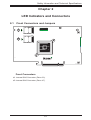
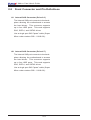
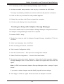
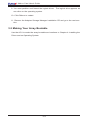
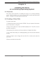
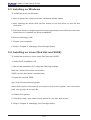
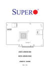
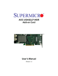
4 C C C A C CC C A A CC A A A C A A PCB EDGE 1 PCB EDGE 1 2 3 4 5 6 7 8 9 10 11 12 13 14 15 16 17 18 19 20 21 22 23 24 25 26 A B C D E F G H J K L M N P R T U V W Y AA AB AC AD AE AF AOC-USAS-S8i AOC-USAS-S8ir USER'S GUIDE Rev. 1.0b Add-on Card User's Guide The information in this User’s Manual has been carefully reviewed and is believed to be accurate. The vendor assumes no responsibility for any inaccuracies that may be contained in this document, makes no commitment to update or to keep current the information in this manual, or to notify any person or organization of the updates. Please Note: For the most up-to-date version of this manual, please see our web site at www.supermicro.com. SUPERMICRO COMPUTER reserves the right to make changes to the product described in this manual at any time and without notice. This product, including software, if any, and documentation may not, in whole or in part, be copied, photocopied, reproduced, translated or reduced to any medium or machine without prior written consent. IN NO EVENT WILL SUPERMICRO COMPUTER BE LIABLE FOR DIRECT, INDIRECT, SPECIAL, INCIDENTAL, SPECULATIVE OR CONSEQUENTIAL DAMAGES ARISING FROM THE USE OR INABILITY TO USE THIS PRODUCT OR DOCUMENTATION, EVEN IF ADVISED OF THE POSSIBILITY OF SUCH DAMAGES. IN PARTICULAR, THE VENDOR SHALL NOT HAVE LIABILITY FOR ANY HARDWARE, SOFTWARE, OR DATA STORED OR USED WITH THE PRODUCT, INCLUDING THE COSTS OF REPAIRING, REPLACING, INTEGRATING, INSTALLING OR RECOVERING SUCH HARDWARE, SOFTWARE, OR DATA. Any disputes arising between manufacturer and customer shall be governed by the laws of Santa Clara County in the State of California, USA. The State of California, County of Santa Clara shall be the exclusive venue for the resolution of any such disputes. Supermicro's total liability for all claims will not exceed the price paid for the hardware product. Manual Revision 1.0b Release Date: August 20, 2008 Unless you request and receive written permission from SUPER MICRO COMPUTER, you may not copy or otherwise reproduce/distribute any part of this document. Information in this document is subject to change without notice. Other products and companies referred to herein are trademarks or registered trademarks of their respective companies or mark holders. Copyright © 2008 by SUPER MICRO COMPUTER INC. All rights reserved. Printed in the United States of America ii Safety Information and Technical Specifications Table of Contents Introduction Overview..............................................................................................................v Product Features..................................................................................................v Operating Systems Supported.............................................................................v Manual Images.....................................................................................................v Contacting SuperMicro........................................................................................vi Chapter 1 Safety Guidelines 1-1 ESD Safety Guidelines......................................................................................... 1-1 1-2 General Safety Guidelines.................................................................................... 1-1 1-3 An Important Note to Users.................................................................................. 1-1 Chapter 2 LED Indicators and Connectors 2-1 Front Connectors and Jumpers....................................................................... 2-1 Front Connectors............................................................................................. 2-1 2-2 Front Connector and Pin Definitions................................................................ 2-2 2-3 Front Jumper Locations and Pin Definitions.................................................... 2-3 LED INDICATORS........................................................................................... 2-4 RAID Minimum Drive Requirements................................................................ 2-4 Chapter 3 Boot Controller and Bootable Array 3-1 Boot Controller Setup........................................................................................... 3-1 3-2 Creating an Array.................................................................................................. 3-1 Creating an Array with the ACU....................................................................... 3-2 Creating an Array with Adaptec Storage Manager.......................................... 3-3 3-3 Making Your Array Bootable................................................................................. 3-4 Chapter 4 Installing the Driver and an Operating System 4-1 Overview............................................................................................................... 4-1 4-2 Creating a Driver Disk.......................................................................................... 4-1 4-3 Installing with Windows......................................................................................... 4-2 4-4 Installing with Red Hat Linux................................................................................ 4-2 4-5 Installing with SUSE Linux.................................................................................... 4-3 Chapter 5 Installing the Driver on an Existing Operating System 5-1 Overview............................................................................................................... 5-1 5-2 Creating a Driver Disk.......................................................................................... 5-1 iii Add-on Card User's Guide 5-3 Installing on Windows........................................................................................... 5-2 5-4 Installing on Linux (Red Hat and SUSE).............................................................. 5-2 Chapter 6 Managing Your Storage Space 6-1 About Adaptec Storage Manager.......................................................................... 6-1 Installing Adaptec Storage Manager................................................................ 6-2 6-2 The Adaptec RAID Controller Configuration Utility............................................... 6-2 6-3 About the Adaptec RAID Configuration Utility...................................................... 6-2 6-4 The Adaptec Flash Utility...................................................................................... 6-3 6-5 Choosing a Utility.................................................................................................. 6-3 iv Safety Information and Technical Specifications Introduction Overview This manual is written for system integrators, PC technicians and knowledgeable PC users who intend to integrate SuperMicro's USAS-S8i Add on Card to their system. Product Features The AOC-USAS-S8i offers the following features: • UIO Form Factor. • Two Internal "ipass" cable ports. • Support for RAID 0, 1, and 10. The AOC-USAS-S8ir offers the following features: • UIO Form Factor. • Two Internal "ipass" cable ports. • Support for RAID 0, 1, 5, 6, 10 and 50. • Preinstalled iButton provides RAID 5, 6 and 50 support. Operating Systems Supported The AOC-USAS-S8i and AOC-USAS-S8ir support the following Operating Systems (OS): • Windows 2000/Windows XP/Windows 2003/Windows 2008/Windows Vista • Red Hat Enterprise Linux/SUSE Linux Each operating systems must include the latest downloads and hot fixes and at least 256 MB of free hard drive space. Manual Images All images and layouts shown in this user's guide are based upon the latest PCB Revision available at the time of publishing. The card you have received may or may not look exactly the same as the graphics shown in this manual. v Add-on Card User's Guide Contacting SuperMicro Headquarters Address: Super Micro Computer, Inc. 980 Rock Ave. San Jose, CA 95131 U.S.A. Tel: +1 (408) 503-8000 Fax: +1 (408) 503-8008 Email: [email protected] (General Information) [email protected] (Technical Support) Web Site: www.supermicro.com Europe Address: Super Micro Computer B.V. Het Sterrenbeeld 28, 5215 ML 's-Hertogenbosch, The Netherlands Tel: +31 (0) 73-6400390 Fax: +31 (0) 73-6416525 Email: [email protected] (General Information) [email protected] (Technical Support) [email protected] (Customer Support) Asia-Pacific Address: Super Micro, Computer Inc. 4F, No. 232-1, Liancheng Rd. Chung-Ho 235, Taipei County Taiwan, R.O.C. Tel: +886-(2) 8226-3990 Fax: +886-(2) 8226-3991 Web Site: www.supermicro.com.tw Technical Support: Email: [email protected] Tel: 886-2-8228-1366, ext.132 or 139 vi Safety Information and Technical Specifications Chapter 1 Safety Guidelines To avoid personal injury and property damage, carefully follow all the safety steps listed below when accessing your system or handling the components. 1-1 ESD Safety Guidelines Electric Static Discharge (ESD) can damage electronic components. To prevent damage to your system, it is important to handle it very carefully. The following measures are generally sufficient to protect your equipment from ESD. • Use a grounded wrist strap designed to prevent static discharge. • Touch a grounded metal object before removing a component from the antistatic bag. • Handle the add-on card by its edges only; do not touch its components, peripheral chips, memory modules or gold contacts. • When handling chips or modules, avoid touching their pins. • Put the card and peripherals back into their antistatic bags when not in use. 1-2 General Safety Guidelines • Always disconnect power cables before installing or removing any components from the computer. • Disconnect the power cable before installing or removing any cables from the system. • Make sure that the add-on card is securely and properly installed on the motherboard to prevent damage to the system due to power shortage. 1-3 An Important Note to Users • All images and layouts shown in this user's guide are based upon the latest PCB Revision available at the time of publishing. The card you have received may or may not look exactly the same as the graphics shown in this manual. 1-1 Add-on Card User's Guide Notes 1-2 Safety Information and Technical Specifications Chapter 2 LED Indicators and Connectors 2-1 Front Connectors and Jumpers 1 4 C C C A C CC C A A CC A A A C A A PCB EDGE 12 PCB EDGE 11 1 2 3 4 5 6 7 8 9 10 11 12 13 14 15 16 17 18 19 20 A B C D E F G H J K L M N P R T U V W Y AA AB AC AD AE AF Front Connectors #1. Internal SAS Connector (Drive 0-3) #2. Internal SAS Connector (Drive 4-7) 2-1 21 22 23 24 25 26 Add-on Card User's Guide 2-2 Front Connector and Pin Definitions #1. Internal SAS Connector (Drive 0-3) The Internal SAS port connects to the backplane allowing the motherboard to access the hard drives. This connector supports up to four HDD ports. This card supports SAS, SATA1, and SATA2 drives. Use a single port SAS "ipass" cable (Super Micro order number CBL - 0108L-02). #2. Internal SAS Connector (Drive 4-7) The Internal SAS port connects to the backplane allowing the motherboard to access the hard drives. This connector supports up to four HDD ports. This card supports SAS, SATA1, and SATA2 drives. Use a single port SAS "ipass" cable (Super Micro order number CBL - 0108L-02). 2-2 Safety Information and Technical Specifications 2-3 Front Jumper Locations and Pin Definitions A A C CC C C CC C A C A C A A A A PCB EDGE 4 FLASH EN 1 PCB EDGE 1 2 3 4 5 6 7 8 9 10 11 12 13 14 15 16 17 18 19 20 21 22 23 24 25 26 A B C D E F G H J K L M N P R T U V W Y AA AB AC AD AE AF Explanation of Jumpers To modify the operation of the backplane, jumpers can be used to choose between optional settings. Jumpers create shorts between two pins to change the function of the connector. Pin 1 is identified with a square solder pad on the printed circuit board. Note: On two pin jumpers, "Closed" means the jumper is on and "Open" means the jumper is off the pins. Connector Pins 3 2 1 3 2 1 Jumper Setting Jumper Settings Jumper Flash Enable Jumper Settings Open = Disable Closed = Enabled Note Enabled allows qualified technician to reprogram the Flash EE Prom and update the chip firmware For normal operation, leave this jumper open. 2-3 Add-on Card User's Guide LED INDICATORS This add-on card includes LED's used to test the product during the manufacturing process. These LED's do not interfere with normal operation and should be ignored. RAID Minimum Drive Requirements Use the following chart to determine the minimum number of hard drives needed to set up a RAID environment. RAID Minimum Hard Drives RAID 0 2 RAID 1 2 RAID 5 3 RAID 6 4 RAID 10 4 (2 RAID 1 Arrays) RAID 50 6 (2 RAID 5 Arrays) 2-4 Safety Information and Technical Specifications Chapter 3 Boot Controller and Bootable Array To section describes the steps required establish a boot controller and a bootable array. If you are creating establishing the boot controller and array on an existing OS, skip to: Installing the Driver on an Existing Operating System. 3-1 Boot Controller Setup To set the system to book for a disk drive or controller array: 1. Enter system setup and navigate to the drive boot sequence. 2 Using the arrows provided or grab and drop, move boot controller to the first item on the list. If your systems supports only one boot controller, go to the next section. For more information, refer to your computer’s documentation. 3-2 Creating an Array This example uses a RAID 1 array (minimum of three hard drives). You can establish an array with a different RAID level or change the array level later. You can create an array using either tool: Array Configuration Utility with keyboard navigation and menu interface (BIOS) or Adaptec Storage Manager available on bootable RAID installation CD (GUI). Warning: Do not mix SAS and SATA drives in the same array. The Adaptec Storage Manager generates a warning if you try to create a logical drive using a combination of SAS and SATA disk drives. 3-1 Add-on Card User's Guide Creating an Array with the ACU Before starting, backup data on your hard disk before beginning. Initializing disks erases data. To create a RAID 1 array: 1 Confirm that your Turn on your computer 2.. When asked, click Ctrl+A to use the ACU utility. If necessary, select your controller from the list of controllers (if you have multiple controllers of the same type), and then click the Enter button. 3 Select Array Configuration Utility, and then click the Enter button. 4 Select Initialize Drives, then click Enter. 5 Select at least three disk drives for the array and do the following: 5a. Click Insert for each selected disk drive 5b. Click Enter. 6 Click Y, and then click Enter. 7 Select Create Array, and then click Enter. 8 Select the disk drives that were just initialized, click Insert for each selected disk drive, then click Enter. 9 At the Array Properties screen opens, use the following settings: 9a. Array Type: Select RAID 1 and click Enter 9b. Array Label: Enter a name the array and click Enter 9c. Array Size: Press Enter twice to use the default GB granularity. 9d. Stripe Size: Click Enter to use the default (256 K) 9e. Read Caching: Click Enter to use the default (Yes) 9f. Write Caching: Click Enter to Enable Always 9g. Create RAID via: Click Enter to choose Build/Verify 3-2 Safety Information and Technical Specifications 10. If necessary, at the cache warning message, type Y for Yes. 11. At the successful array creation, click any key to return to the ACU Menu. The array immediately available at reduced until the build process is finished 12. Click the Esc key until the Exit utility window appears. 13. Select Yes, and then click Enter to restart the computer. 14. Continue with Making Your Array Bootable. Creating an Array with Adaptec Storage Manager This section details how to use the Adaptec Storage Manager configuration wizard. The Adaptec Storage Manager Install CD is required. To create a RAID 1 array: 1. Restart the computer with the Adaptec Storage Manager Installation CD in the CD drive. 2. Select your language, then click Enter. 3. After reviewing the license, click Enter. 4. Click Launch Configuration Utility. 5. Click the Create button. This opens the Configuration Wizard. 6. Select "ExClick configuration..." and click the Next button. 7. Review the information that is displayed. Notice that for this example, Adaptec Storage Manager used 13 disk drives to create one logical drive and one hot spare. Note: In DAS environments, Adaptec Storage Manager refers to arrays "logical drives". If you want to make changes use the Modify logical devices settings. 8. Click Apply to build the logical drives and save the Adaptec controller. 3-3 Add-on Card User's Guide 9. You must partition and format the logical drives. The logical drive appears as one drive on the operating system. 10. Click Reboot to restart. 11. Remove the Adaptec Storage Manager Installation CD and go to the next section. 3-3 Making Your Array Bootable Use the ACU to make the array bootable and continue to Chapter 4: Installing the Driver and an Operating System. 3-4 Safety Information and Technical Specifications Chapter 4 4-1 Overview Installing the Driver and an Operating System This chapter details the following tasks: ● Adaptec RAID installation ● Bootable Array creation ● Driver Disk creation 4-2 Creating a Driver Disk To create a driver disk: 1 Configure the system to boot from the CD-ROM. See your system's documentation for instructions on doing this. 2 Power on the system and insert the RAID Installation CD. This CD is found in the RAID controller kit. 3 Navigate past the welcome and license windows to Adaptec Start Menu. 4 Click Create Driver Disk(s) for Installing/Updating your OS and select Windows or Linux. 5 When prompted, insert a floppy disk and click Ok to continue and create the driver disk 6 Remove and label the driver disk. 4-1 Add-on Card User's Guide 4-3 Installing with Windows Before beginning locate your Windows Installation CD. To install the Adaptec RAID controller driver (during Windows installation): 1 Insert the Windows installation CD. 2. Restart the computer. 3. Follow the on-screen instructions to begin the Windows installation. When asked to install a third-party driver, click F6. If you miss the opportunity to initiate the F6 command, you must restart the computer. 4 Insert the driver disk, then wait until you are prompted to install a driver. 5 Choose the floppy disk as the source of the driver and then click Enter. 6 When prompted, click Enter to continue. 7 Follow the on-screen instructions to complete OS installation. 8 Continue to Chapter 6: Managing Your Storage Space. 4-4 Installing with Red Hat Linux This task requires the Red Hat Installation CD to complete this task. To install the Adaptec RAID controller driver (during Red Hat Linux installation). 1. Insert the Red Hat Installation CD (the first one) and restart the system. 2. At the Welcome screen appears, type linux dd at the Boot: prompt. 3. When prompted, insert the driver disk, then select OK. 4. Linux allows you to set up the specific type of environment you desire. . 5. Install any third party devices and click Done. 6. Follow the on-screen instructions to complete OS installation. 7. Continue to Chapter 6: Managing Your Storage Space. 4-2 Safety Information and Technical Specifications 4-5 Installing with SUSE Linux To install the Adaptec RAID controller driver (during SUSE Linux installation). 1. Insert the SUSE Installation CD (the first one) and restart the system. 2. At the SUSE Linux installation selection screen, choose the installation type and click F6 to use a driver disk. (For older versions of SUSE Linux, use the Alt key) 3. When prompted, insert the driver disk. (Click any key to move forward) 4. Linux allows you to set up the specific type of environment you desire. . 5. Install any third party devices and click Done. 6. Follow the on-screen instructions to complete OS installation. 7. Continue to Chapter 6: Managing Your Storage Space. 4-3 Add-on Card User's Guide Notes 4-4 Safety Information and Technical Specifications Chapter 5 Installing the Driver on an Existing Operating System 5-1 Overview This section gives instruction on installing the drivers on an existing Operating system. Before installation you must the Adaptec RAID controller and internal disk drives. In addition, you must create the driver disk. 5-2 Creating a Driver Disk To create a driver disk: 1 Configure the system to boot from the CD-ROM. See your system's documentation for instructions on doing this. 2 Power on the system and insert the RAID Installation CD. This CD is found in the RAID controller kit. 3 Navigate past the welcome and license windows to Adaptec Start Menu. 4 Click Create Driver Disk(s) for Installing/Updating your OS and select Windows or Linux. 5 When prompted, insert a floppy disk and click Ok to continue and create the driver disk 6 Remove and label the driver disk. 5-1 Add-on Card User's Guide 5-3 Installing on Windows To install the driver on Windows: 1 Start or restart the system the New Hardware Wizard opens. 2 After inserting the driver disk, set the wizard to use the driver on the dis and click Next. 3 Click Next twice to navigate past the license agreements and follow the onscreen instructions to complete the driver installation. 4 Remove the floppy disk. 5. Restart your computer. 6. Skip to Chapter 6: Managing Your Storage Space. 5-4 Installing on Linux (Red Hat and SUSE) To install the module on Linux (both Red Hat and SUSE). 1. Insert RAID Installation CD. 2. Mount the Installation CD using the following settings. Red Hat: mount /dev/cdrom /mnt/cdrom SUSE: mount /dev/cdrom /media/cdrom 3. Install the module RPM: rpm -Uvh mount-point/xxx/yyy.rpm where mount-point is the specific mount point on the Linux system, xxx is the driver path, and yyy.rpm is the rpm file. 4. Reboot the system. 5. Run fdisk, mkfs, and create mount points for any new disk drives. 6. Skip to Chapter 6: Managing Your Storage Space. 5-2 Safety Information and Technical Specifications Chapter 6 Managing Your Storage Space This chapter details how to create and manage your storage space once the controller and required drivers have been installed. This chapter also details the Adaptec Storage Manager and other Adaptec RAID controller utilities. 6-1 About Adaptec Storage Manager The Adaptec Storage Manager allows administrators to build a storage space for online data by grouping disk drives into logical drives. The logic drive protect data through redundancy. The Adaptec Storage Manager also allows administrators to manage controllers and drives from one work station. This includes DAS and NAS. Installing the Adaptec Storage Manager automatically installs the Adaptec Storage Manager agent. The agent is a service (running in the background) that monitors system health, events notifications, and other processes on the system. For more information, see the Adaptec Storage Manager online Help, or documentation included on the Adaptec Storage Manager Installation CD. Note: FreeBSD does not support the Adaptec Storage Manager to create/configure arrays. Use theARC utility instead. 6-1 Add-on Card User's Guide Installing Adaptec Storage Manager For installation file and instructions, see the Adaptec Storage Manager Installation CD. This CD also includes a User’s Guide for Internal RAID Storage and other documentation. 6-2 The Adaptec RAID Controller Configuration Utility The Adaptec RAID Controller Configuration (ARCCONF) provides basic array and configuration management functions. The ARCCONF is a command line tool which can create/remove logical drives, change configuration settings, and allow administrators to troubleshoot problems. Specific instructions for using the ARCCONF can be ARCCONF and the Command Line Interface (CLI) for Internal RAID Storage User’s Reference, which describes how to use ARCCONF, are included on the Adaptec Storage Manager Installation CD. Note: It is recommended that only advanced users familiar with command line interfaces use ARCCONF. Currently, ARCCONF is not supported on FreeBSD. To create and manage arrays, use theARC utility. 6-3 About the Adaptec RAID Configuration Utility The Adaptec RAID Configuration (ARC) utility allows administrators to manage controllers, disk drivers and arrays. It is intended pre-operating system installation use. This utility includes the following tools: Array Configuration Utility, A -Select utility, and Disk Utilities. The Array Configuration Utility (ACU) creates and manages arrays and drives. The A -Select utility modifies the controller and disk drive settings (includes SerialSelect, SATASelect®, and SCSISelect®). Disk Utilities formats disk drives. 6-2 Safety Information and Technical Specifications 6-4 The Adaptec Flash Utility The Adaptec Flash Utility (AFU) allows administrators to update, save, and manage RAID controller firmware BIOS and NonVolatile RAM. The utility is text based. It is recommended that, although the AFU provides safeguards against improper configuration, AFU management should be performed by an experienced technician or administrator. Improper use may damage the RAID controller. 6-5 Choosing a Utility It is recommended that administrators use the BIOS-based ACU to create a bootable array and the Adaptec Storage Manager for storage management tasks. 6-3 Add-on Card User's Guide Notes 6-4