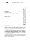
1
POCKET GSM
0
.11
V
nd
EM
2a
3
D
.
0
80 V
MO
S1 Kbps e
D
C
d
6
D
N
.
A
00/ to 9 xt mo
B
9
p
M
u Te
S
AL
EG ssion and t
d
DU
i
an sm DU or
al-B Tran port P supp
u
D ta up Fax le
Da S s and adab
SM ice pgr
Vo ash U
Fl
User’s Guide
rev. 3.1 12/2004
http://www.digicom.it
PocketGSM
Index
INDEX
PREFACE
ENVIRONMENTAL CONDITIONS
CLEANING THE TERMINAL
VIBRATIONS OR DROPPING
DECLARATION CE OF CONFORMITY
1. INTRODUCTION
1.1. TECHNICAL FEATURES
1.2. WARNINGS
2. INSTALLATION
2.1. PIN-OUT CONNECTOR
2.2. SIM CARD
2.3. CONNECTION TO THE EXTERNAL ANTENNA
2.4. POWER SUPPLY
2.5. LED INDICATORS
2.6. CONNECTOR FOR THE VOICE MANAGEMENT
3. FUNCTIONAL EXAMPLES
4. AT COMMANDS
4.1. COMMANDS NOTES
4.2. AT COMMANDS DESCRIPTION
4.2.1. GENERAL COMMANDS
4.2.2. 07.07 GSM COMMANDS
4.2.3. PHONEBOOK COMMANDS
4.2.4. VOICE COMMANDS
4.2.5. SMS CONTROL COMMANDS (GSM 07.05)
4.2.6. GPIO COMMANDS (GENERAL PURPOSE INPUT OUTPUT)
4.2.7. GPRS COMMANDS (GSM 07.07)
APPENDIX A
I
II
II
II
II
II
1.1
1.1
1.1
2.1
2.1
2.2
2.2
2.4
2.5
2.6
3.1
4.1
4.1
4.2
4.2
4.11
4.18
4.20
4.24
4.30
4.37
A.1
PocketGSM
Preface
PREFACE
All rights reserved; no part of this publication may be reproduced, stored in a retrieval system, or transmitted
in any form or by any means, electronic, otherwise, without the prior written permission of Digicom S.p.A.
The following installation rules should be respected in order to have the best working order of the equipment
and for the user’s safety.
ENVIRONMENTAL CONDITIONS
Enviromental temperature Relative humidity
from -20 to +55°C
from 20 to 80% n.c.
Rapid changes of temperature or humidity should be avoided.
This equipment, including cables, should be installed in an area free from:
Dust, humidity, heat from direct sun light.
Objects which irradiate heat. These could cause damage to the container or other problems.
Objects which produce a strong electtromagnetic field (loudspeakers, etc.)
Liquids or chemical corrosive substances.
CLEANING THE TERMINAL
Use a clean and soft cloth. Wet the cloth with water or natural detergent if it is necessary to remove any
stains. Never use chemical products such as petrol or solvents.
VIBRATIONS OR DROPPING
Caution against vibrations and dropping.
DECLARATION
OF CONFORMITY
We, Digicom S.p.A. registered office at: via Volta 39 - 21010 Cardano al Campo (Varese - Italy) declare
under our sole responsability that the product:
Name: POCKET GSM Type: Modem Dual-Band GSM 900/1800MHz
satisfies the basic requirement of the below indicated Directive:
1999/5/CE of March 9 1999, R&TTE
as having been designed in conformity with the requirements of following Reference Standards:
EN 60950
EN 301 489-1
EN 301 489-7
EN 301-419-1
EN 301-511
II
PocketGSM
1.
Introduction
INTRODUCTION
Congratulation on choosing digicom PocketGSM.
Pocket GSM is a GSM Dual-Band modem (EGSM900/DCS1800), perfect for DATA, SMS,
FAX and VOICE applications.
It has been designed to operate on any digital GSM network both directly and in roaming.
PocketGSM is compliant with GSM Class 4 (900Mhz) and Class 1 (1800 Mhz). The dual
band functionality depends on the network. Please refer to GSM provider for the availability
of the service.
1.1. TECHNICAL FEATURES
Power Supply
Power Supply:
Temperature
Operating:
Storage:
Connectors
Power Supply & I/O:
Data interface:
Antenna:
Audio:
SIM:
Size
Size:
Weight:
from 5 to 32 Vdc
from -20°C to +55°C
from -20°C to +70°C
Mini-Fit™ 12 pin (Molex 556912A1)
9 pin RS232 (V24/V28)
SMA female
RJ6 female (telephone handset)
Plug-In 3V
87x75x25mm
about 130gr
1.2. WARNINGS
Satefy
Read carefully these instructions and notes before powering PocketGSM. For each situation
please follow the specific instructions. 1.1
PocketGSM
Introduction
PocketGSM is a low power radio transmitter and receiver. When it is ON, it sends receives
radio frequency (RF) signals.
PocketGSM produces magnetic fields. Do not place it next to magnetic support such as
floppy disks, tapes, et. . Operating your modem close to other electrical equipment such
as television, phone, radios and personal computer, may cause interference.
Interference
PocketGSM, like all wireless devices, is subject to interferences that may reduce its performances.
Road Safety
Do not use PocketGSM while driving. In case of use on cars, it is necessary to check that electronic
equipment is shielded against RF signal. Do not place PocketGSM over the air bag or in the air bag
deployment area.
Aircraft Safety
Switch off PocketGSM in aircraft by disconnecting the Power cable. Using GSM devices on aircraft is
illegal.
Hospital Safety
Do not use PocketGSM near health equipment, especially pacemaker and hearing aids, to avoid potential
interferences. PocketGSM is a not mobile phone, do not use it in direct contact with the human body.
Switch it off in hospitals, and medical center. Hospitals or health care facilities may be using equipment
that could be sensitive to external RF energy.
Explosive Materials
Do not use PocketGSM in refuelling points, near fuel or chemicals. Do not use the PocketGSM where
blasting is in progress. Observe restrictions, and follow any regulation or instruction.
Instructions for use
Do not use PocketGSM in direct contact with the human body, do not touch the antenna if not necessary
when the phone is in use. Use approved accessories and batteries only. Do not connect incompatible
products.
1.2
PocketGSM
2.
Installation
INSTALLATION
The GSM modem installation must be carried out between a range of temperature indicated
in the manual.
Attention: the power supply voltage must not exceed the indicated maximum value as this may cause
a damage of the product.
2.1. PIN-OUT CONNECTOR
Connect the serial port of your device to PocketGSM through a 9 pin RS232 right standard
connector .
This table describes the position of the signals on Pocket GSM connector:
9 pin female connector (DCE)
5
9
1
6
Pin
1
2
3
4
5
6
7
8
9
Description
Data Carrier Detect
Receive Data
Transmitted Data
Data Terminal Ready
Signal Ground
Data Set Ready
Request To Send
Clear To Send
Ring Indicator
Initials
DCD
RD
TD
DTR
GND
DSR
RTS
CTS
RI
In case your application supports TD and RD (transmission and reception)signals only, it
is possible to connect it to the Pocket GSM. In this case it is important to configure
PocketGSM to ignore the not present criteria.
[ For further information about commands, see the chapters “Functional Examples” and “AT
Commands”; you’ll find the “AT Commands” chapter in the user’s manual present on Digicom
website ]
The modem can receive AT commands at the speeds between 300 and 115200 bit/s.
2.1
PocketGSM
Installation
2.2. SIM CARD
Plug-in SIM are supported by PocketGSM.
To prevent damaging or losing information avoid touching the sim gold area.
Attention: Check with your GSM provider if your SIM is enable for data and fax traffic, if not ask him for
this service, he will give you other two numbers (one for data calls and the other for fax calls).
Insert the SIM
Probably the SIM card will be supplied in a card holder compliant with the devices using
the full-size SIM.
1. Remove the SIM carefully from the SIM holder.
2. Turn off Pocket GSM, by disconnecting the power connector.
3. Discover the SIM slot and press on the release pin with a finger or
a pencil.
4. Insert the SIM card into the holder. Be sure the angled corner is top
right.
5. Close the SIM holder and press it up to the end. Do not force the
SIM holder and verify the correct position. .
2.3. CONNECTION TO THE EXTERNAL ANTENNA
To connect the external antenna go on as follows:
1. Turn off your Pocket GSM by disconnecting the power
connector.
2. Connect the SMA male connector to the external antenna of
Pocket GSM, screwing it clockwise.
3. Place the antenna and check there is a good quality signal.
2.2
PocketGSM
Installation
You can check the signal:
Using a cellular phone
Insert the SIM of the PocketGSM in a cellular phone and check the quality of the signal.
Through the Led STATUS
Power on the modem and verify the STATUS Led. If it is red blinking, it means the modem is recognized
by the GSM network. In this way you can check the signal but not its quality.
Attention: even if you see the STATUS Led blinking, it may not be sufficient for data transmission.
Through the AT+CSQ command
By using this command it is possible to detect a more precise signal. Power on PocketGSM and connect
it to a Personal cpmputer, using a serial cable. With a hyperterminal send to the modem the command
AT+CSQ.
The modem will answer with +CSQ: x,y; where “x” is the signal quality, “y” is the BER (But Error Rate).
The value of “x” can be included between 0 to 31; the higher value indicates a better signal.
From 0 to 9 : poor
From 10 to 15 : good
From 16 to 31 : excellent
99 = Unknown or uncalculable
BER values higher than 2 may compromise the good operation of the device. In this case place the
antenna in a better position.
[ For further information about commands, see the chapters “Functional Examples” and “AT
Commands”; you’ll find the “AT Commands” chapter in the user’s manual present on Digicom
website ]
Attention: for better performances of the supplied stilo antenna, we suggest to position it upwards. Try
to fix Pocket GSM and its antenna at least one meter from the floor.
In case you use a different antenna, do not fix it directly to the mechanics of the product or on
metal surfaces.
2.3
PocketGSM
Installation
2.4. POWER SUPPLY
The inputs, outputs and power supply use a Minifit 12 pin connector:
Frontal view
PIN
1
2
3
4
5
6
7
8
9
10
11
12
Description
OUTPUT 2 (Open Collector)
OUTPUT 1 (Open Collector)
DIGITAL INPUT 4
DIGITAL INPUT 3
DIGITAL INPUT 2
DIGITAL INPUT 1
N.C.
N.C.
Power supply from 5 to 32Vdc
GND
ANALOG INPUT 2
ANALOG INPUT 1
(GPO2)
(GPO1)
(GPIO5)
(GPIO4)
(GPIO0)
(GPI3)
(ADC2)
(ADC1)
pin 9 : positive [from +5 to +32Vdc]
pin 10 : negative [GND]
The modem has a special protection in case you accidentally invert the polarity.
The modem power supply must be included between 5 and 32 Vdc with ground negative.
Attention: the power supply voltage must not exceed the indicated maximum value as this may cause
a damage of the product.
2.4
PocketGSM
Installation
2.5. LED INDICATORS
Through two led indicators you can control the status of Pocket GSM:
LED
POWER
STATUS
OFF
ON
OFF
ON
STATUS
SLOW BLINKING
FAST BLINKING
DESCRIPTION
No power supply
Power supply on
No power supply
PocketGSM is in one of the following status:
- network search mode;
- SIM card not present;
- PIN not inserted;
- emergency mode.
PocketGSM detected by the GSM network
PocketGSM connected to another device
PocketGSM is ready to work only after it has been registered by the GSM network and
with a good quality signal.
To verify that PocketGSM is ready for calls and SMS, follow these commands:
COMMAND
AT+CPIN?
AT+CREG?
AT+COPS?
AT+CSQ
DESCRIPTION
Verifies the presence of the SIM and the PIN code
Verifies the registration to the GSM network
Verifies the current GSM operator
Verifies the quality of GSM signal
[ For further information about commands, see the chapters “Functional Examples” and “AT
Commands”; you’ll find the “AT Commands” chapter in the user’s manual present on Digicom
website ]
2.5
PocketGSM
Installation
2.6. CONNECTOR FOR THE VOICE MANAGEMENT
For the voice functionality, Pocket GSM is equipped with a double ended audio interface
on RJ6 female connector with the same Pin-out of a standard telephone handset
The interface can be connected both to a handset or to a loud speaking telephone.
VOICE connector Pin-Out (RJ6)
4
3
2
1
Microphone ( + )
2
Speaker ( + )
3
Speaker ( - )
4
Microphone ( - )
1
The modem includes AC coupling and biasing for electret microphone.
Suggested characteristics for the microphone
Polarizzazione :
2V – 0.5mA
Impedance:
2KΩ
Sensitivity :
from –40dBm to –50dBm
SNR (Signal to Noise Ratio) : > 50dBm
Suggested characteristics for the speaker
Type :
10mW, electro-magnetic
Impedance :
from 32 to 150 Ω
Suggest configuration
AT+SPEAKER=0
AT+ECHO=0
AT+SIDET=1,3
[ For further information see the chapter “AT Commands” present in the user’s manual on Digicom
website ]
2.6
PocketGSM
3.
Functional Examples
FUNCTIONAL EXAMPLES
Pocket GSM can be programmed through a set of AT commands for the execution of all its
functionalities.
If you are using a PocketGSM/GPRS, information for the GPRS functionality are present
in “AT Commands” chapter. It is present in the user’s manual on Digicom web site.
Here the description of some applications. For the complete AT command set, see the
chapter “AT Commands”.
Attention: In the factory configuration the AT commands are managed at 9600bit/s only (the PocketGSM/
GPRS at 115200bit/s only). Before going on with your settings, you must set your terminal emulator
(e.g. HyperTerminal) or your application as follows: 9600,8,N,1 (with PocketGSM/GPRS: 115200,8,N,1)
then you can modify the interface speed with the values included between 300 and 115200bit/s
with the command AT+IPR.
[ For further information see the chapter “AT Commands” present in the user’s manual on Digicom
website ]
A) PIN management
B) PocketGSM ready to work
C) Serial cable not completed
D) Data transfer
E) SMS Management (Text mode)
3.1
PocketGSM
Functional Examples
A) PIN MANAGEMENT
Due to security reasons, usually SIM cards require the insertion of PIN code. With Pocket
GSM you can insert the PIN code through the AT+CPIN command.
If your application has other security systems, you can disable the PIN request using a
mobile phone.
Examples:
Command:
Answer:
Answer:
Answer:
Answer:
Answer:
AT+CPIN?
ERROR
+CPIN: READY
+CPIN: SIM PIN
+CPIN: SIM PUK
+CPIN: SIM PIN2
(Verify the SIM and the PIN status)
(SIM card reading failed)
(PIN code present: SIM ready)
(PIN code insertion is required)
(PUK code insertion is required)
(PIN2 code insertion is required)
In case the PIN code is not present, it must be inserted before using the SIM card:
Command:
AT+CPIN=4321
(PIN insertion)
Answer:
OK
(PIN code right)
Answer:
ERROR
(PIN code wrong)
Attention: remember that if the PIN code is wrongly inserted for three times, the SIM card will block. To
unblock it you must insert the PUK code.
[ For further information see the chapter “AT Commands” present in the user’s manual on Digicom
website ]
3.2
PocketGSM
Functional Examples
B) POCKET GSM READY TO WORK
PocketGSM can work only after it has been detected by the network and with a good GSM
signal. To verify PocketGSM is ready to manage calls and SMS, follow these commands:
Command:
Answer:
AT+CPIN?
+CPIN: READY
Command:
Answer:
AT+CREG?
+CREG: 0,1
OK
(GSM modem is registered by the network)
Command:
Answer:
AT+COPS?
+COPS: 0,2,22288
OK
(PocketGSM is registered at operator 22288)
Command:
Answer:
AT+CSQ
+CSQ: 15,0
OK
(GSM signal: good)
(SIM is ready)
The CSQ value can be included between 0 and 31, where 0 = –113dBm and
31 = –51dBm.
Every unit corresponds to 2 dBm.
From 0 to 9 = not sufficient
From 10 to 15 = good
From 16 to 31 = excellent
[ For further information see the chapter “AT Commands” present in the user’s manual on Digicom
website ]
3.3
PocketGSM
Functional Examples
C) SERIAL CABLE NOT COMPLETED
In case your application (eg. PLC) supports only TD and RD signals (Trasmission and
Reception), it is however possible to connect it to the PocketGSM. In this case you will
use a non-completed serial cable; for this reason it is important to configure PocketGSM
so that it ignores the serial criteria not present. Usually PocketGSM, during the
communication phase, checks the following criteria: 108 (Data Terminal Ready) and 105
(Request To Send): to disable them use the commands AT&D and AT+IFC.
Examples:
Command:
AT&D0
Command:
AT&D2
Answer:
OK
Command:
Command:
Answer:
(Criterion 108 ignored)
(Criterion 108 managed as per specification)
AT+IFC=0,0 (Criterion 105 ignored: flow control OFF)
AT+IFC=2,2 (Criterion 105 managed as per specification: flow control ON)
OK
D) DATA TRANSFER
PocketGSM can call and be called by analog (PSTN), digital (ISDN) and GSM devices.
Usually DATA connections with analog modems are at 9600bit/s (V.32 protocol); ISDN
connections use V.110 protocol with speed at 9600bit/s. The data transfer with another
GSM device is carried out using V.32 or V.110 protocols.
DATA Calls
Using the ATD command it is possible to make a call. For example, to call the number
0123456789 you must send to the modem the command ATD0123456789<Enter>.
Depending on the AT+CBST command setting it is possible to program PocketGSM for
analog, digital or GSM calls:
AT+CBST=0,0,1 connection with analog or GSM modems in multistandard (V.32)
AT+CBST=7,0,1 connection with analog or GSM modems only in V.32 at 9600bit/s
AT+CBST=71,0,1 connection with digital or GSM modem only in V.110 at 9600bit/s
3.4
PocketGSM
Functional Examples
Attention: check with your telephone operator if your SIM is enabled for DATA and eventually for FAX.
In fact most SIMs are enabled for Voice(call and reception) while for DATA and FAX only the call is
enabled.
To enable the reception of DATA and FAX traffic it is necessary to ask the telephone operator that
will assign two additional numbers (one to receive DATA calls and one to receive FAX calls).
Examples:
Command:
Answer:
Command:
Answer:
AT+CBST=7,0,1
OK
ATD0123456789
CONNECT 9600
V.32 call at 9600bit/s
Command:
Answer:
Command:
Answer:
AT+CBST=71,0,1
OK
ATD0123456789
CONNECT 9600
V.110 call at 9600bit/s
DATA calls reception
Generally in PocketGSM the automatic answer is disabled (S0=0): in this case the modem
will answer only after it received the ATA command.
In case you want to enable the automatic answer, you must set the S0 register with the
number of rings after which to answer (eg. S0=2 automatic answer after two rings).
PocketGSM factory configuration has the AT+CBST=0,0,1 setting, in this way it will be
able to answer to any call coming from an analog, ISDN or GSM modem.
[ For further information see the chapter “AT Commands” present in the user’s manual on Digicom
website ]
E) SMS MANAGEMENT (TEXT mode)
PocketGSM manages the SMS in TEXT and PDU format.
Send an SMS (TEXT mode)
You find here the necessary commands to send SMS in TEXT mode.
3.5
PocketGSM
Functional Examples
1) Reading and Setup of the Services Center
To activate the SMS management, you must insert the identifier number of the Services
Center for your GSM operator. In the most recent SIM cards, the identifier is already
present in memory: to verify you can use a mobile phone or, with Pocket GSM, you can
act as follows:
Command:
Answer:
AT+CSCA?
+CSCA: “+393205858500”,145
OK
(reading of Services Center)
(Services Center present)
If the Services Center number is not present, ask the telephone operator, then insert the
identifier as follows:
Command:
Answer:
Command:
Answer:
AT+CSCA=”+393359609600”
OK
AT+CSAS
OK
(eg. TIM Services Center)
(Save the number of Services Center)
Attention: the above mentioned numbers (Services Centers) could be modified by the telephone
operator. In case of error after you send the SMS, check the identifier of the Services Center with
your Telephone Operator.
2) Define the mode
Command:
AT+CMGF=1
Answer:
OK
Command:
Answer:
AT&W
OK
(TEXT mode)
(Save the configuration)
3) Send a message:
Command:
AT+CMGS=”+393217654321”<enter>
Answer:
>
3.6
PocketGSM
Text:
Answer:
Functional Examples
First SMS message with Pocket GSM<ctrl z>
+CMGS: <sms index>
OK
After you digit yuor message, press <ctrl z> (Hex =1A).
In this example the message “First SMS message with Pocket GSM” is sent to number
+393217654321.
Attention In case of error after you send the SMS, check the identifier of the Services Center with your
Telephone Operator.
Read the SMS (TEXT mode)
The factory configuration of PocketGSM detects the coming of a new SMS. When an
SMS arrives, PocketGSM send to the DTE (eg. PC) the following message: +CMTI: “SM”,2
(2 indicates the memory location of the SIM card where the SMS has been stored). To
read the message use the AT+CMGR command:
Command:
Answer:
AT+CMGR=2
+CMGL: 2,"REC UNREAD","+393217654321",,"01/01/75,12:05:46+04"
Second SMS message with PocketGSM
To display all the messages present in the SIM memory:
Command:
Answer:
AT+CMGL=”ALL”
+CMGL: 1,"REC READ","+393217654321",,"01/01/75,12:05:46+04"
First SMS message with Pocket
+CMGL: 2,"REC UNREAD","+393217654321",,"01/01/75,12:06:26+04"
Second SMS message with PocketGSM
OK
3.7
PocketGSM
Functional Examples
Through the AT+CNMI command it is possible to program the PocketGSM so as it sends
immediately the received message to the DTE (eg. PC):
Command:
Answer:
AT+CNMI=2,2
OK
With this configuration PocketGSM sends immediately the message to the DTE, when it
receives it from the network:
+CMT: "+393217654321",,"01/01/75,12:06:14+00"
First SMS message with Pocket GSM
Cancel the SMS
For example, to cancel the second message:
Command:
Answer:
AT+CMGD=2
OK
[ For further information see the chapter “AT Commands” present in the user’s manual on Digicom
website ]
3.8
PocketGSM
4.
AT Commands
AT COMMANDS
PocketGSM supports a complete AT commands set to configure and test the modem and
all its functionalities.
These commands are based on the following recommandations:
ETSI GSM 07.07: Digital cellular telecommunications system (Phase 2); AT command
set for GSM Mobile Equipment (ME);
ETSI GSM 07.05: Digital cellular telecommunications system (Phase 2); Use of DTEDCE interface for Short Message Service (SMS) and Cell Broadcast Service (CBS);
ITU-T Recommandation V.25ter: Serial asynchronous automatic dialling and control.
The factory configuration of PocketGSM accepts AT commands only at 9600bit/s (the
PocketGSM/GPRS only at 115200bit/s). Before going on you must set your terminal
emulator (e.g. HyperTerminal) or your application with these values:
Bit per second
data bit
parity
stop bit
flow control
= 9600 (with PocketGSM/GPRS : 115200)
=8
= None
=1
= Hardware (RTS/CTS)
Use the commands AT+IPR, AT+ICF, AT+IFC to change the modem interface speed and
the flow control.
4.1. COMMANDS NOTES
Please read these before using PocketGSM:
The commands always start with AT; it means Attention, and end with <CR> (Hex=0D)
character.
The answer messages in extended format (ATV1 command) start and end with
<CR><LF> (Hex=0D 0A). If Pocket GSM is programmed to manage numeric answers
4.1
PocketGSM
AT Commands
(ATV0), then the answer will not have the prefix <CR><LF> and will be ended with the
<CR> character.
To disable the answer messages use ATQ1 command.
If the syntax of the command is wrong, the modem sends the answer ERROR
If the syntax of the command is correct but some incorrect parameters are used, the
strings +CME ERROR: <Err> or +CMS ERROR: <SMSErr> are sent with different
error codes.
If the command has been successfully executed, the answer will be OK.
(In some cases, such as AT+CPIN? the modem will return the information requested
without OK).
[In the “Functional Examples”, and in the “AT commands description”, the characters <CR>
and <CR><LF> have been intentionally omitted.]
4.2. AT COMMANDS DESCRIPTION
4.2.1.
GENERAL COMMANDS
ATA
Answer an incoming call
When the modem receives a call, it sets the Ring Indicator signal and sends to the DTE
(e.g. PC) the RING string (or +CRING: <type> if AT+CRC=1). If the automatic answer is
disabled (ATS0=0), the ATA command enables the answer to an incoming call.
Command
ATA
Possible answers
CONNECT
OK
Action
DATA call accepted
VOICE call accepted
ATD
Dial command
This command will dial the number entered after the ATD string. When the modem detects
the carrier from the GSM base station, it will answer with the message CONNECT: at this
point the data transmission starts.
For further information on ATD command, see chapter “Functional Examples”.
4.2
PocketGSM
Command
ATD<str>
<str>
Numbers 0...9
+
;
L
>”text”
>mem<idx>
>n
AT Commands
Possible answers
CONNECT
OK
BUSY
NO ANSWER
NO CARRIER
Action
DATA / FAX connection is established
VOICE connection is established
Remote device busy
No answer from the called number
Failed or refused call
Description
Examples
National call
ATD0123456789
International call
ATD+987654321
At the end of the number for the VOICE calls
ATD0123456789;
Redial the last called telephone number
ATDL
Call to the number in the phonebook associated with the “text” indentifier
(by AT+CPBS command)
ATD>”Digicom”
Call to the number contained in mem position n
ATD>SM2
Call to the number stored in the position n of the current phonebook;
it can be selected with the AT+CPBS command
ATD>1
ATE
Echo command
When the modem receives a command, it executes the echo of the received characters.
With this command it is possible to enable and disable the echo.
Command
ATE0
ATE1
Default: ATE1
Possible answers
OK
OK
Action
Echo disabled
Echo enabled
ATH
Hang up
When the modem is on-line after the escape sequence “+++”, this command forces the
modem to disconnect.
Command
Possible answers
Action
ATH
OK
The modem disconnects
4.3
PocketGSM
AT Commands
ATO
Back to On-Line mode
If you have to interrupt the data flow temporarily to verify the modem status or some
registers without disconnecting, you can use the “+++” escape sequence. Then send the
AT0 command to return to data mode.
Command
ATO
Possible answers
CONNECT
Action
Back to On-Line mode
ATQ
Answer messages
This command is used to enable and disable the modem answers.
Command
ATQ0
ATQ1
Default: ATQ0
Possible answers
OK
OK
Action
Answer messages enabled
Answer messages disabled
ATS0
Auto answer
The S0 register allows to disable (ATS0=0) or to enable the modem autoanswer when
arriving an incoming call.
Command
ATS0=<n>
ATS0?
Default: ATS0=0
Possible answers
OK / ERROR
OK
Action
Auto answer after n rings
Reading of S0 register
ATV
Result code format
This command determines the modem response format: verbose code or numeric code.
Command
ATV0
ATV1
Default: ATV1
Possible answers
OK
OK
Action
Result code display as digit
Result code display as words
4.4
PocketGSM
AT Commands
ATZ
Load user profile
This command will load a user profile previously saved with the AT&W command.
Command
ATZ
Possible answers
OK
Action
Loads the user profile
AT%D
Automatic dialing with DTR (C108)
This command allows to activate a DATA or VOICE autocall to the number stored in the
first location of the SIM phonebook; or the automatic sending of an SMS stored in the SIM
first location.
The number is dialed when DTR passes from OFF to ON status; the short message is
sent when DTR passes from OFF to ON status.
Command
AT%D0
AT%D1
AT%D1;
AT%D2
Default: AT%D0
Possible answers
OK
OK
OK
OK
Action
Function disabled
Enables automatic dialing (DATA)
Enables automatic dialing (VOICE)
Enables automatic sending of the SMS
AT&C
Data Carrier Detect (C109)
This command defines the management of the DCD (C109) on the modem serial port. If
controlled (AT&C1), the DCD ON indicates the connection with a remote device. If forced
(AT&C0) regardless of the status (connected/disconnected), the DCD is always ON.
Note: Data Carrier Detect can be controlled in DATA and FAX modes only.
Command
AT&C0
AT&C1
Possible answers
OK
OK
Action
Data Carrier Detect always ON
Data Carrier Detect is controlled and
follows the connection status
Default: AT&C1
4.5
PocketGSM
AT Commands
AT&D
Data Terminal Ready (C108)
This command defines the management of the DTR (C108) on the modem serial port.
The DTR comes from the DTE (e.g. PC) to the modem, for this reason the criterion can be
present or absent. If absent, the modem must be configured to ignore the criterion (AT&D0).
If present, the modem will accept the call only if the criterion is ON.
For further information on AT&D command, see chapter “Functional Examples”.
Command
AT&D0
AT&D1
Possible answers
OK
OK
AT&D2
OK
Action
DTR is ignored
Modem switches from data to
command mode when DTR
switches from ON to OFF.
When DTR switches from ON to OFF
the modem disconnects.
Default: AT&D2
AT&F
Restore factory settings
This command is used to load the factory settings for the command listed in the table.
Command
AT&F
Possible answers
OK
Commands restored with AT&F
Q
S0
V
+CMGF +CNMI
+COPS
+ECHO +ILRR
+SIDET
Action
Loads the factory configuration
%D
+CBST
+CR
+CRC
+SPEAKER +VGR
+CLIP
+CREG
+VGT
+CMEE
+CSMP
AT&S
Data Set Ready (C107)
This command defines the management of DSR (C107) criterion present on the modem
serial port. If controlled (AT&S1), the DSR ON indicates a connection with a remote device.
When OFF it indicates the disconnection with the remote modem. If forced (AT&S0),
regardless of the status (connected/disconnected), the DSR is always ON.
Note: Data Set Ready can be controlled in DATA and FAX modes only.
4.6
PocketGSM
Command
AT&S0
AT&S1
AT Commands
Possible responses
OK
OK
Action
Data Set Ready always ON
Data Set Ready is controlled and
follows the connection status
Default: AT&S1
AT&V
Command
AT&V0
AT&V1
AT&V2
Display configuration
Possible answers
OK
OK
OK
Action
Displays the current configuration
Displays the stored configuration
Displays the factory configuration
AT&W
Save current configuration
This command saves the active configuration, in the EEPROM.
Command
AT&W
Possible answers
OK
Action
Saves the configuration
This commands can be saved with AT&W
E
Q
S0
V
&C
&D
+CLIP +CMEE
+CMGF
+COPS
+CR
+CRC
+IFC +ILRR
+IPR
+SIDET
+SPEAKER
&S
+CBST
+CREG +ICF
+VGR
+VGT
+++
Escape command
By sending the escape sequence, the modem switches from data to command mode. If
the escape sequence is followed by the ATH command, the connection will be ended.
Note: the escape sequence works only with AT+ICF=3,4 (8N1) or =5,1 (7E1)
Command
+++
Possible answers
OK
Action
Return to command mode
4.7
PocketGSM
AT Commands
AT+CGMM Model identification
Command
AT+CGMM
Possible answers
MULTIBAND 900E 1800
OK
Action
Device identification
AT+CGMR Modem firmware release
Command
AT+CGMR
Possible answers
432a09gm.2D
OK
Action
Modem firmware release
AT+CGSN Product Serial Number (IMEI)
Command
AT+CGSN
Possible answers
012345678901234
Action
International Mobile Equipment
Identity (IMEI) of the GSM module
OK
AT+CIMI
IMSI (International Mobile Subscriber Identity)
This command is used to read and identify the IMSI of the SIM card.
Command
AT+CIMI
Possible answers
222016200858803
OK
Action
222 : Mobile Country Code (222 = Italy)
01 : Mobile Network Code (01 = Tim)
6200858803 : Mobile Subscriber
Identification Number
AT+IPR
Fixed DTE rate
This command specifies the data rate at which the modem will accept data from the DTE
(e.g. PC); the answer messages from the modem will use the same speed.
4.8
PocketGSM
AT Commands
Command
Possible answers
AT+IPR=<speed>
OK / ERROR
AT+IPR?
+IPR: 9600
AT+IPR=?
+IPR: (0,2400,…)
Default: AT+IPR=9600 (the PocketGSM/GPRS AT+IPR=115200)
<speed>
0
From 300 to 115200 bit/s
Action
Set the interface rate
Shows the current speed
Shows the available speeds
Description
Autobaud enabled: the modem automatically detects the speed, monitoring
the received AT command.
Interface speed set at one of the following values: 300, 600, 1200, 2400, 4800,
9600, 19200, 38400, 57600, 115200 bit/s.
AT+ICF
Data format
This command allows to select the data synchronous format, the modem will use to accept
data from the DTE (e.g. PC); the modem answer messages will use the same format.
Note: a data format different from 8N1 ( AT+ICF=3,4) disables the autobaud (AT+IPR=0) if active. If the
data format is set at 8N1, the autobaud is automatically enabled.
Comando
AT+ICF=<format>,<parity>
AT+ICF?
AT+ICF=?
Default: AT+ICF=3,4
Possibili risposte
OK / ERROR
+ICF: 5,1
+ICF: (1-6), (0-4)
<format>
1
2
3
4
5
6
Data Format
Data: 8bit;
Data: 8bit;
Data: 8bit;
Data: 7bit;
Data: 7bit;
Data: 7bit;
Azione
Set data format
Shows the current settings
Shows the available settings
Parity: 0bit (None);
Parity: 1bit;
Parity: 0bit (None);
Parity: 0bit (None);
Parity: 1bit;
Parity: 0bit (None);
4.9
Stop: 2bit
Stop: 1bit
Stop: 1bit
Stop: 2bit
Stop: 1bit
Stop: 1bit
PocketGSM
AT Commands
<parity>
0
1
2
3
4
Examples
AT+ICF=3,4
AT+ICF=5,0
AT+ICF=5,1
Parity Format
Odd
Even
Mark
Space
None
Data: 8bit;
Data: 7bit;
Data: 7bit;
Parity: None;
Parity: Odd;
Parity: Even;
Stop: 1bit
Stop: 1bit
Stop: 1bit
AT+IFC
Flow control
This command is used to set the flow control to be used.
For further information on the AT+IFC command, see the chapter “Functional Examples”.
Command
AT+IFC=0,0
AT+IFC=2,2
AT+IFC?
AT+IFC=?
Default: AT+IFC=2,2
Possible answers
OK
OK
+IFC: 2,2
+IFC: (0,2), (0,2)
Action
Flow control disabled
Enables the Hardware flow control (RTS/CTS)
Shows the current flow control
Shows the available values
AT+ILRR Interface speed report
This command gives a report for the serial port speed, before the connection message.
Command
AT+ILRR=0
AT+ILRR=1
AT+ILRR?
AT+ILRR=?
Default: AT+ILRR=0
Possible answers
OK
OK
+ILRR: 0
+ILRR: (0,1)
4.10
Action
Report disabled
Report enabled
Shows the current settings
Shows the available settings
PocketGSM
4.2.2.
AT Commands
07.07 GSM COMMANDS
AT+CBST Line Speed Setting
This command is used to select the line speed and the protocol for the DATA calls.
If Multistandard is selected:
when transmitting, the modem sets with the maximum speed available on the GSM
network (for Italy V.32 9600 bit/s)
when receiving the modem recognizes the speed and the protocol suggested from the
remote device.
For further information on AT+CBST command, see the chapter “Functional Examples”.
Command
Possible answers
AT+CBST=<speed>,<mode>,<ce> OK / ERROR
AT+CBST?
+CBST: 0,0,1
AT+CBST=?
+CBST: (0-7…), (0),…
Default: AT+CBST=0,0,1
<speed>
0
1
2
4
6
7
66
68
70
71
<mode> <ce>
0
1
0
1
0
1
0
1
0
1
0
1
0
1
0
1
0
1
0
1
Description
Multistandard
V.21
300 bit/s
V.22
1200 bit/s
V.22 bis 2400 bit/s
V.32
4800 bit/s
V.32
9600 bit/s
V.110
1200 bit/s
V.110
2400 bit/s
V.110
4800 bit/s
V.110
9600 bit/s
4.11
Action
Sets the speed and the protocol
Shows the current settings
Shows the available settings
No Transparent
No Transparent
No Transparent
No Transparent
No Transparent
No Transparent
No Transparent
No Transparent
No Transparent
PocketGSM
AT Commands
AT+CEER Extended error report
This command gives a report with the cause of the last disconnection.
(See Appendix A for the error codes).
Command
AT+CEER
Possible answers
+CEER: Error <err>
OK
Action
Cause of last disconnection
AT+CFUN Modem Restart
The AT+CFUN=1 command is used for a software reset of the modem; this means also a
new registration to the GSM network. Before carrying out a reset, we suggest to save the
current configuration (AT&W).
The AT+CFUN=0 or AT+CPOF commands are used to switch the modem in Stand-by
mode: during this phase the modem is disconnected from the GSM network.
To exit from the Stand-by mode use the AT+CFUN=1 command.
Command
Possible answers
AT+CFUN=0 (o AT+CPOF) OK
AT+CFUN=1
OK
Action
Modem in Stand-by
Modem restart
AT+CLIP
Calling Line Identification (CLI)
When receiving a call, this command allows to identify the calling number. With the
command AT+CLIP? It is possible to obtain the status of the “CLIP Service” in the network.
The caller ID is displayed after any RING message.
Command
AT+CLIP=0
AT+CLIP=1
AT+CLIP?
Possible answers
OK
OK
+CLIP: 0,<n>
AT+CLIP=?
Default: AT+CLIP=0
+CLIP: (0,1)
4.12
Action
CLI displaying is disabled
CLI displaying id enabled
Shows the current settings and the
CLIP Service state
Shows the available settings
PocketGSM
<n>
0
1
2
AT Commands
CLIP Service status in the network (reading only)
CLIP Service not available
CLIP Service available
Service Status: Unknown (no network…)
AT+CLIR Calling Line Identification restriction (CLI)
This command allows to hide the Calling Line Identification to the remote device.
Note: Independently from the setting of AT+CLIR, it is possible to add an “i” small letter at the end of
the calling string to present the CLI to the remote user (e.g. ATD0123456789i); or the letter “I”
capital letter to hide the CLI (e.g. ADT0123456789I).
Command
AT+CLIR=0
Possible answers
OK
AT+CLIR=1
AT+CLIR=2
AT+CLIR?
OK
OK
+CLIR: 0,<n>
AT+CLIR=?
Default: AT+CLIR=0
+CLIR: (0-2)
<n>
0
1
2
3
4
Action
CLI presentation depends on the
CLIR Sevice status.
CLI is not displayed
CLI is displayed
Shows the current settings and CLIR
Service status
Shows the available settings
CLIR Service status in the network (reading only)
CLIR Service not available
CLIR Service available
Service Status: Unknown (no network…)
CLIR Service temporary suspended
CLIR Service temporary available
AT+CMEE Report Mobile Equipment errors
This command enables the report +CME ERROR: <err> and +CMS ERROR <SMSerr>
with the indication of the error code, instead of a generic answer. (See Appendix A for
error codes).
4.13
PocketGSM
AT Commands
Command
AT+CMEE=0
AT+CMEE=1
AT+CMEE?
Default: AT+CMEE=0
Possible answers
OK
OK
+CMEE: 0
Action
Report disabled
Report enabled
Shows the current settings
AT+COPS Operator selection
PocketGSM can automatically detect the GSM operator both directly and in roaming. With
this command you can check the current provider. Moreover, in extreme cases it is possible
to force the registration to a specific provider: in this case check the registration status
with the command AT+CREG.
With the command AT+COPS=? it is possible to verify the situation of the operators: 0
unknown operator; 1 operator is available; 2 current operator; 3 the operator is forbidden
and cannot be selected.
For further information on AT+COPS command, see the chapter “Functional Examples”.
Command
AT+COPS=<mode>,
<format>,<oper>
AT+COPS?
AT+COPS=?
Default: AT+COPS=0,2
<mode>
0
1
4
<format>
0
1
2
<oper>
Possible answers
OK / ERROR
Action
Selects the operator
+COPS: 0,2,22201
+COPS: (2,"I TIM”,”TIM”,”22201”)…
Shows the current operator
Shows the available operators
Registration mode
Automatic (<oper> is ignored)
Manual
If manual selection fails, automatic mode is entered
Operator format
Long alphanumeric format (e.g. I OMNITEL)
Short alphanumeric format (e.g. OMNI)
Numeric format (e.g. 22210)
Operator identifier
4.14
PocketGSM
AT Commands
AT+CPIN Enter PIN code
This command is used to enter the PIN and PUK codes. If the SIM card, used with Pocket
GSM, has the PIN code enabled, it will be necessary to insert it each time you turn the
modem on, to permit the registration to the GSM network.
The PIN and the PUK code management can be carried out with any mobile phone.
For further information on the PIN code management, see chapter “Functional Examples”.
Attention: If the PIN code is three times wrongly inserted, the SIM card is blocked. To unblock, insert
the PUK code and the new PIN code. (e.g. AT+CPIN=12345678,1234).
Command
AT+CPIN=<pin>
AT+CPIN=<puk>,<pin>
AT+CPIN?
<status>
+CPIN: READY
+CPIN: SIM PIN
+CPIN: SIM PUK
+CPIN: SIM PIN2
ERROR
Possible answers
OK / ERROR
OK / ERROR
<status>
Action
PIN code insertion
PUK and PIN insertion
Shows the SIM status
Description
PIN code is present: SIM ready
PIN is required
PUK is required
PIN2 is required
SIM card reading failed
AT+CR
Connection report
This command enables the report +CR: <type> that identifies the current connection. The
report is given before the connection message.
Command
AT+CR=0
AT+CR=1
AT+CR?
Default: AT+CR=0
Possible answers
OK
OK
+CR: 0
4.15
Action
Report disabled
Report enabled
Shows the current settings
PocketGSM
AT Commands
AT+CRC
Cellular Result Code
This command enables the report +CRING: <type>, instead of the traditional RING
message.
Command
AT+CRC=0
AT+CRC=1
AT+CRC?
Default: AT+CRC=0
Possible answers
OK
OK
+CRC: 0
Action
Report disabled
Report enabled
Shows current settings
AT+CREG GSM Network registration
This command enables the automatic report to any change of status during the modem
registration to the GSM network.
For further information on AT+CREG command, see the chapter “Functional Examples”.
Command
AT+CREG=<n>
AT+CREG?
Possible answers
OK
+CREG: <n>,<stat>,[<lac>,<ci>]
AT+CREG=?
Default: AT+CREG=0
+CREG: (0-2)
<n>
0
1
2
<stat>
0
1
2
3
4
5
Action
Report enabled or disabled
Shows the current registration status
of the GSM modem to the network
Shows the available settings
Report status
Report disabled
Report enabled with +CREG: <stat>
Report enabled with +CREG: <stat>,<lac>,<ci>
Registration status
Modem not registered, PocketGSM is not currently searching for a new operator
Modem registered with the same operator of the SIM card
Modem not registered, PocketGSM is searching for a new operator
Registration denied
Registered at an unknown network
Modem registered in roaming
4.16
PocketGSM
<lac>
<ci>
AT Commands
Location Area Code in hexadecimal format (e.g. “00C3” is the same as “195”
in decimal)
Cell ID in hexadecimal format
AT+CSQ
GSM Signal Quality
This command is used to control the GSM quality signal.
For further information on AT+CSQ command, see the chapter “Functional Examples”.
Command
AT+CSQ
Possible answers
+CSQ: <rssi>,<ber>
OK
<rssi>
Reception level
0
-113 dBm or less
1
-111 dBm
2…30
-109…-53 dBm
31
-51 dBm or greater
99
unknown or not detectable
Note: each unit corresponds to 2 dBm
<ber>
0
1
2
3
4
5
6
7
99
bit error rate
ber < 0,2%
0,2% < ber < 0,4%
0,4% < ber < 0,8%
0,8% < ber < 1,6%
1,6% < ber < 3,2%
3,2% < ber < 6,4%
6,4% < ber < 12,8%
ber > 12,8%
unknown or not detectable
4.17
Action
Reads the signal power and ber
PocketGSM
AT Commands
4.2.3. PHONEBOOK COMMANDS
AT+CPBS Select Phonebook
This command selects the memory to be used for the phonebook.
Command
AT+CPBS=<”storage”>
AT+CPBS?
Possible answers
OK / ERROR
+CPBS: <“storage”>,<used>,
<total>
Action
Select the current phonebook memory
and the available memory
Default: AT+CPBS=”ME”
<”storage”> Phonebook
“ME”
Modem phonebook (250 memory locations)
“SM”
SIM phonebook (the number of locations depends on the SIM)
“LD”
Last 10 dialled numbers
“RC”
Last 10 received calls
<used>
Locations used
<total>
Total locations
AT+CPBW Write and cancel a telephone number
This command allows to write or to delete a telephone number in the current phonebook.
It can be selected with the command AT+CPBS.
Command
Possible answers
AT+CPBW=<index>,<”number”>, OK / ERROR
<type>,<”text”>
AT+CPBW=<index>
OK
AT+CPBW=?
+CPBW: (lista <index>),
<ilength>,(lista <type>),
<tlength>
4.18
Action
Insert the telephone number
Cancel the telephone number
Shows the information on the
memory of the selected phonebook
PocketGSM
AT Commands
<index> Location where to save the telephone number
<”number”> telephone number
<type>
145 if <”number”> includes the “+” character in the international prefix
129 if <”number”> does not include the “+” character in the international prefix
Note: this parameter can be omitted.
<”text”>
Mnemonic name of the telephone number
<ilength> Max length for <”number”>
<tlength> Max length for <”text”>
Examples
AT+CPBW=1,”+39320xxxxxxx”,,”Ufficio Roma”
AT+CPBW=2,”320xxxxxxx”,129,”Ufficio Napoli”
AT+CPBW=3,”320xxxxxxx”,,”Casa”
AT+CPBW=3
Location 1 inserted
Location 2 inserted
Location 3 inserted
Location 3 cancelled
AT+CPBR Read a telephone number
This command is used to read a telephone number in the current phonebook and can be
selected with the command AT+CPBS.
Command
AT+CPBR=<idx1>,<idx2>
<idx1> e <idx2>
AT+CPBR=1
AT+CPBR=1,10
Possible answers
+CPBR:
<idx1>,<number>,<type>,<text>
…
<idx2>,<number>,<type>,<text>
Location range
Read entry 1
Read entries from 1 to 10
4.19
Action
Reads the numbers in the phonebook
from <idx1> to <idx2>
PocketGSM
AT Commands
AT+CPBF Search for a telephone number (knowing the stored text)
This command is used to find a telephone number inside the phonebook, knowing the
associated identifier (e.g. starting with D…).
Command
AT+CPBF=<”text”>
Possible answers
+CPBF:
<idx1>,<number>,<type>,<text>
<idx2>,<number>,<type>,<text>
Action
Displays the telephone numbers
with the specified <”text”> identifier
AT+CPBP Search for a telephone number (knowing the number)
This command is used to find an identifier associated with a telephone number inside the
phonebook, knowing the number itself.
Command
AT+CPBP=<”number”>
Possible answers
+CPBP:
<idx1>,<number>,<type>,<text>
Action
Displays the identifier
associated with the specified <”number”>
4.2.4. VOICE COMMANDS
PocketGSM can call another voice device with the ATD<number>; command:
e.g.ATD0123456789;
When the remote device answers the call, PocketGSM will show the OK message.
For the voice functionality, PocketGSM is equipped with a double-ended audio interface
on RJ6 female connector with the same Pin-out of a standard telephone handset.
The interface can be connected both to a handset and to a loud speaking telephone.
In order to improve the quality of the voice it will be necessary to modify some parameters
to delete the echo, the noise, etc. In this paragraph you can find the commands necessary
to improve the voice quality. To save the configuration use the AT&W command.
4.20
PocketGSM
AT Commands
AT+SPEAKER Speaker and Microphone selection
With a single command, you can set the factory parameters of the commands: AT+VGR,
AT+VGT, etc; in this way you can quickly improve the quality of the voice.
Note: Act also on AT+VGR, AT+CGT, commands to improve the quality of the voice. If there is noise
you could connect an external antenna with extension cable.
Command
AT+SPEAKER=0
AT+SPEAKER?
Default: AT+SPEAKER=0
Possible answers
OK
+SPEAKER: 0
Action
Configuration for “telephone handset”
Shows the current settings
AT+CMUT Mute Control
During a voice connection, this command disables the microphone while the speaker is
always active.
Command
AT+CMUT=0
AT+CMUT=1
AT+CMUT?
Default: AT+CMUT=0
Possible answers
OK
OK
+CMUT: 0
Action
Microphone enabled
Microphone disabled (MUTE)
Shows the current settings
AT+VTS
Send DTMF tones
During a voice connection, this command sends the DTMF tones, to allow the surfing in
vocal servers.
Note: wait always the OK, before sending another tone.
Command
Possible answers
AT+VTS=<DTMF>
OK / ERROR
<DTMF> DTMF tones
0…9
Numbers from 0 to 9
#
# character
*
Asterisk character
A…D
A, B, C, D characters
4.21
Action
Send the specified DTMF tone
PocketGSM
AT Commands
AT+VTD
Length of the DTMF tone
This command is used to increase or reduce the length of the DTMF tone, sent with the
command AT+VTS.
Command
AT+VTD=<time>
AT+VTD?
Default: AT+VTD=1
<time>
1
2
…
10
…
Possible answers
OK / ERROR
+VTD: 1
Action
Sets the length of the DTMF tone
Shows the current settings
DTMF tones
100 milliseconds
200 milliseconds
…
1 second
…
AT+VGR
Speaker gain control
This command is used to set the receiving level of the speaker.
(See Appendix A for the values of the speaker gain).
Command
AT+VGR=<val>
AT+VGR?
Possible answers
OK / ERROR
+VGR: 64
Action
Sets the receiving level of the speaker
Shows the current settings
AT+VGT
Microphone gain control
This command is used to set the transmission level of the microphone.
(See Appendix A for the values of the microphone gain).
Command
AT+VGT=<val>
Possible answers
OK / ERROR
AT+VGT?
+VGT: 64
4.22
Action
Sets the transmission level of
the microphone
Shows the current settings
PocketGSM
AT Commands
AT+ECHO Echo cancellation
This command enables the echo cancellation for voice calls in small rooms. It could be
necessary to act on the (AT+VGT) and (AT+VGR) commands for a best voice quality.
Command
Possible answers
AT+ECHO=<mode>,<algold>
OK / ERROR
AT+ECHO?
+ECHO: <status>,<algold>
Action
Sets the echo cancellation
Shows the current settings
<mode> Mode
0
Echo disabled
1
Echo enabled
Note: you can enable/disable the echo cancellation during a call without restarting the modem if you
don’t change the Algorithm.
<algold> Algorithm
1
Echo cancellation 1
3
Echo cancellation 3
<status> Status
0
Eco disabled
1
Eco enabled for “telephone handset”
2
Eco enabled for “loud speaking telephone”
3
Module reset
AT+SIDET SideTone Control
This command is used to set the echo level of the voice in the speaker (to have a microphone
feedback in the speaker).
Command
AT+SIDET=0,<val>
AT+SIDET=1,<val>
AT+SIDET?
Possible answers
OK / ERROR
OK / ERROR
+SIDET: 1,1
4.23
Action
SideTone disabled
SideTone enabled
Shows the current settings
PocketGSM
<val>
0
1
2
3
AT Commands
Description
0 db
-6db
-12db
-18db
AT+VIP
Voice parameters Initialization
This command allows to restore the factory settings for the voice parameters from
EEPROM. These voice parameters include: AT+SPEAKER; AT+CMUT; AT+VGR; AT+VGT
AT+ECHO; AT+SIDET.
Command
AT+VIP=1
4.2.5.
Possible answers
OK
Action
Restores the factory settings
SMS CONTROL COMMANDS (GSM 07.05)
AT+CMGF Messages format
This command is used to define the SMS format (Short Message Service).
For further information on AT+CMGF command, see the chapter “Functional Examples”.
Command
AT+CMGF=0
AT+CMGF=1
AT+CMGF?
Possible answers
OK
OK
+CMGF: 1
Action
SMS in PDU mode
SMS in Text mode
Shows the current settings
AT+CSCA Service Center Number
This command allows to set the Service Center number in the SIM card memory. An error
will occur if trying to send an SMS using a wrong number of the Services Center. Verify
with your GSM Operator the number of the Service Center.
For further information on AT+CSCA command, see the chapter “Functional Examples”.
4.24
PocketGSM
AT Commands
Command
Possible answers
AT+CSCA?
+CSCA: “Service Center Address”
AT+CSCA=“ Service Center OK
Address”
Action
Displays the Service Center number
Inserts the Service Center number
AT+CSMP Period of Validity for the SMS
This command is used to define period of validity of the message in the Services Center.
Command
AT+CSMP=<fo>,<vp>,
<pid>,<dcs>
AT+CSMP?
Possible answers
OK / ERROR
Action
Sets the period of validity
+CSMP:
<fo>,<vp>,<pid>,<dcs>
Shows the current settings
Default: AT+CSMP=1,167
<fo>
<vp>
“11“
“71“
“167“
“173”
“255”
<pid>
<dcs>
Reserved (value is 1, do not modify)
Period of validity
1 hour
6 hours
24 hours
1 week
Higher
Reserved
Reserved
AT+CSAS Save settings
This command allows to save the settings of the following commands: AT+CSCA, AT+CSMP
and AT+CNMI.
For further information on AT+CSAS command, see the chapter “Functional Examples”.
Command
AT+CSAS
Possible answers
OK
4.25
Action
Save the current settings
PocketGSM
AT Commands
AT+CRES Restore settings
This command restores the setting of the following commands: AT+CSCA, AT+CSMP and
AT+CNMI.
Command
AT+CRES
Possible answers
OK
Action
Restore the saved settings
AT+CNMI Indication of New incoming message
This command displays a report when a new SMS arrives.
For further information on AT+CNMI command, see the chapter “Functional Examples”.
Command
AT+CNMI=<mode>,<mt>
AT+CNMI?
Default: AT+CNMI=0,1
<mode>
2
0,1,3
<mt>
0
1
2
Possible answers
OK / ERROR
+CNMI: <mode>,<mt>
Action
Select the report display mode
Shows the current settings
Display Mode
If the modem is Off-line, the message will be displayed on the DTE in <mt>
format.
If the modem is On-line, the message will be displayed on the DTE in <mt>
format at the end of the connection.
Equal to 2
Report format
No report
Report with format:
+CMTI: <mem>,<index>
Report with format:
+CMT:<oa>,[<alpha>],<scts>[,<tooa>,<fo>,<pid>,<dcs>,<sca>,<tosca>,<lengh>]
<data>
4.26
PocketGSM
AT Commands
Examples
1) AT+CNMI=2,1
Report: +CMTI: "SM",2
Description: The received SMS has been stored in the location 2 of the SIM memory.
2) AT+CNMI=2,2
Report: +CMT: "+393217654321",,"01/01/75,12:06:14+00"
First SMS message with PocketGSM
Description: the received SMS is displayed directly on the DTE.
AT+CMGD Delete messages
This command is used to delete the SMS messages stored in the SIM memory.
For further information on AT+CMGD command, see the chapter “Functional Examples”.
Command
Possible answers
AT+CMGD=<index>,<deflag> OK / ERROR
<index>
<deflag>
0
1
2
3
4
Action
Cancella i messaggi SMS
Memory index
Delete method
Delete the message in the <index> position.
If <deflag> value is omitted, it will be equal at 0.
Delete all the received and read messages: “REC READ”. The <index> value
is ignored.
Delete all the received, read, saved and sent messages: “REC READ” and
“STO SENT”. The <index> value is ignored.
Delete all the received, read, saved, sent and unsent messages: “REC READ”,
“STO SENT” and “STO UNSENT”. The <index> value is ignored.
Delete all messages. The <index> value is ignored.
4.27
PocketGSM
AT Commands
AT+CMGL Messages List
This command displays the list of the SMS messages stored in the SIM memory.
For further information on AT+CMGL command, see the chapter “Functional Examples”.
Command
AT+CMGL=<stat>
<stat>
Possible answers
OK / ERROR
Action
Shows the list of SMS
Display method
Text mode
PDU mode
“REC UNREAD”
0
“REC READ”
1
“STO UNSENT”
2
“STO SENT”
3
“ALL”
4
Description
Displays all the received unread messages
Displays all the received and read messages
Displays all the stored unsent messages
Displays all the stored sent messages
Display all the messages
AT+CMGR Display message
This command allows to display a specific SMS stored in the SIM memory
For further information on AT+CMGR command, see the chapter “Functional Examples”.
Command
AT+CMGR=<index>
Possible answers
OK
Action
Shows the message
AT+CMGS Send SMS
This command is used to send a SMS message in Text mode.
For further information on AT+CMGS command, see the chapter “Functional Examples”.
Examples
Command:AT+CMGS=”+393217654321”<enter>
Answer: >
Text:
First SMS message with PocketGSM<ctrl z>
Answer: +CMGS: <sms index>
OK
4.28
PocketGSM
AT Commands
Compose your message, press <ctrl z> (Hex =1A). To cancel the procedure, press <esc>
(Hex = 1B).
In this example the message “First SMS message with Pocket GSM” is sent to number
+393217654321.
AT+CMSS Send a stored SMS
This command is used to send a previously stored SMS message in Text format. Check
the memory location with the AT+CMGL=”ALL” command.
Command
AT+CMSS=<index>
Possible answers
OK
Action
Sends the SMS message stored in <index> location
AT+CMGW Store an SMS
This command is used to store an SMS message in text format into the SIM memory.
Examples
Command:AT+CMGW=”+393217654321”<enter>
Answer: >
Text:
First SMS message with PocketGSM<ctrl z>
Answer: +CMGW: <sms index>
OK
Compose your message, press <ctrl z> (Hex =1A). To cancel the procedure, press <esc>
(Hex = 1B).
In this example the message “First SMS message with Pocket GSM” is stored.
4.29
PocketGSM
AT Commands
4.2.6. GPIO COMMANDS (GENERAL PURPOSE INPUT OUTPUT)
Besides the functionalities for the DATA, SMS, FAX and VOICE management, Pocket
GSM can also read some inputs contacts and control some output relays.
Thanks to this characteristic, you will be able to build a complete application using a single
device:
you can detect the status change of an input and send an SMS alarm;
you can receive a specific SMS and control a output relay.
In this paragraph you find the characteristics of the General Purpose Input/Output (GPIO)
and the AT commands to control them.
MINIFIT CONNECTOR
The inputs, the outputs and the power supply are managed through a Minifit connector
(12 pin):
Frontal view
(1)
PIN Description
1 OUTPUT 2 [Open Collector]
2 OUTPUT 1 [Open Collector]
3 INPUT DIGITALE 4
4 INPUT DIGITALE 3
5 INPUT DIGITALE 2
6 INPUT DIGITALE 1
7 N.C.
8 N.C.
9 from +5 to +32Vdc
10 GND
11 INPUT ANALOGICO 2
12 INPUT ANALOGICO 1
If you use the complete connector with 12 cables.
4.30
(GPO2)
(GPO1)
(GPIO5)
(GPIO4)
(GPIO0)
(GPI3)
(ADC2)
(ADC1)
Wire color (1)
Yellow
Green
Blue
Light Blue
Brown
Violet
White
Grey
Red
Black
Pink
Orange
PocketGSM
AT Commands
Power on PocketGSM connecting the cable with the correct polarity:
pin 9: positive [from +5 to +32Vdc]
pin 10: negative [GND]
The modem has a special protection in case you accidentally invert the polarity.
CHARACTERISTICS OF GPIO CONTACTS
PocketGSM supports:
4 digital inputs (two logical states: ON/OFF);
2 analog inputs;
2 output open-collector.
Digital Inputs
Two status are supported for each input: open or closed to
ground.
It is necessary connect only a free contact (without voltage)
between the input pin (pin 6, 5, 4, 3) and the ground pin (pin 10).
DIGITAL INPUT CHARACTERISTICS
Permitted status: Input open
Input closed to ground (GND)
Analog Inputs
Two Analog to Digital Converter are available on the PocketGSM. These converters have
a 10 bit resolution, ranging from 0 to 28 Vdc.
ANALOG INPUT CHARACTERISTICS
Resolution
10bit
Input signal range From 0 to 28Vdc
To read the value, use AT+ADC command. Send AT+ADC=1 command and read the
value with AT+ADC? command.
4.31
PocketGSM
AT Commands
Command
AT+ADC?
Possible answers
+ADC: <ADC3>,<ADC2>,<ADC1>
Action
Shows the current value
Ignore the first value <ADC3>; read only ADC1 and ADC2. This command gets the (DC
level * 1024) of ADC1 and ADC2.
Output
The two outputs of PocketGSM (old and new version), manage the
devices that can be activated and deactivated through a switch.
(e.g. Lamp, Sound, Logic Port, etc...).
To connect your devices, check the Transistor characteristics: max
collector-emitter voltage (Vce) and collector current (Ic):
Vce (max):
Ic (max):
45V
500mA
4.32
PocketGSM
AT Commands
Connection Examples
If you want to manage a simple led (1,5V – 20mA), with a 12V
power supply, you must add a pull-up resistor (470Ω) to limit
the current.
If you want to manage a lamp with 230V
power supply, you can connect an external
rele and a diode (1N4007 or 1N4148) to
protect the transistor inside the PocketGSM
Note: if you use a cable to connect the rele,
connect the diode close to the pin1 or pin2 of
the PocketGSM to protect the transistor inside
the PocketGSM.
4.33
PocketGSM
AT Commands
AT+WIOM Input/Output Configuration
This command allows to configure the 6 contacts I/O. If they are configures as Output, it is
possible to establish the default status (Reset or Set) at every restart.
Command
Possible answers
AT+WIOM=<IODir>,<IOVal> OK / ERROR
AT+WIOM?
+WIOM: <IODir>,<IOVal>
<IODir>
bit 0
bit 1
bit 2
bit 3
bit 4
bit 5
bit 6-7
<IOVal>
0
2
4
6
Action
GPIO configured
Shows the current settings
GPIO direction (Input or Output) (bit mapped register)
0 = GPIO0 configured as Input
1 = GPIO0 configured as Output
1 = GPO1 configured as Output
1 = GPO2 onfigured as Output
0 = GPI3
configured as Input
0 = GPIO4 configured as Input
1 = GPIO4 configured as Output
0 = GPIO5 configured as Input
1 = GPIO5 configured as Output
Not used
Output default value after reset (bit mapped register)
OUTPUT1 Reset
OUTPUT2 Reset
OUTPUT1 Set
OUTPUT2 Reset
OUTPUT1 Reset
OUTPUT2 Set
OUTPUT1 Set
OUTPUT2 Set
Remember:
The Open Collector outputs are usually OPEN.
4.34
PocketGSM
AT Commands
Possible settings
AT+WIOM=6,0 GPIO0
GPO1
GPO2
GPI3
GPIO4
GPIO5
AT+WIOM=6,2
AT+WIOM=6,4
AT+WIOM=6,6
INPUT2
OUTPUT1
OUTPUT2
INPUT1
INPUT3
INPUT4
GPIO0
GPO1
GPO2
GPI3
GPIO4
GPIO5
INPUT2
OUTPUT1
OUTPUT2
INPUT1
INPUT3
INPUT4
GPIO0
GPO1
GPO2
GPI3
GPIO4
GPIO5
INPUT2
OUTPUT1
OUTPUT2
INPUT1
INPUT3
INPUT4
GPIO0
GPO1
GPO2
GPI3
GPIO4
GPIO5
INPUT2
OUTPUT1
OUTPUT2
INPUT1
INPUT3
INPUT4
(initial state: Reset)
(initial state: Reset)
(initial state: Set)
(initial state: Reset)
(initial state: Reset)
(initial state: Set)
(initial state: Set)
(initial state: Set)
4.35
PocketGSM
AT Commands
AT+WIOR Read GPIO value
This command reads the current state (Reset or Set) of an Input. It is not possible to read
the state of an Output. Trying to read an Output status will cause an ERROR.
Command
AT+WIOR=<Index>
Possible answers
+WIOR: <Val>
Action
Reads the current status
<Index>
Digital Input index (values: 0, 3, 4, 5)
AT+WIOR=3 Reads the Digital Input 1 status
AT+WIOR=0 Reads the Digital Input 2 status
AT+WIOR=4 Reads the Digital Input 3 status
AT+WIOR=5 Reads the Digital Input 4 status
<Val> Digital Input state
0
Reset
1
Set
AT+WIOW Write GPIO value
This command writes the state (Reset o Set) of an Output. It is not possible to write the
state of an Input. Trying to write an Input status will cause an ERROR.
By default (after a power off/on) the Output contact is set by AT+WIOM command.
Command
Possible answers
AT+WIOW=<Index>,<Val> OK / ERROR
<Index>
Output index (values 1, 2)
AT+WIOW=1,<Val>
Writes the Output 1 status
AT+WIOW=2, <Val>
Writes the Output 2 status
<Val>
GPIO state
0
Reset
1
Set
4.36
Action
Writes the output status
PocketGSM
4.2.7.
AT Commands
GPRS COMMANDS (GSM 07.07)
The GPRS functionality is available only in some versions of PocketGSM. If available for
the best use of the GPRS function, we suggest to set AT+IPR=0 (autobaud) and to save
the configuration with AT&W command. After the driver installation, select in driver
properties the interface speed at 115200.
GPRS activation
Verify with your GSM Operator the GPRS activation.
GPRS configuration
To configure PocketGSM for GPRS connection, you must send the AT+CGDCONT to se
the access profile to the service.
Check with the GSM Operator your access profile.
AT+CGDCONT=1,”IP”,”APN”
You can insert the AT+CGDCONT command in the Additional string in the driver properties
or send the command by HyperTerminal and save it with AT&W command.
Connection
Now you are ready for a Dial-Up connection and a GPRS connection, using the drivers.
Verify with your GSM Operator the GPRS parameters (e.g. User ID, password, phone
number).
For further technical information and for the driver, see the Support area on our web site www.digicom.it,
or send a e-mail to [email protected]
4.37
PocketGSM
Appendix A
A
APPENDIX A
A1.
(+CEER: Error <err>) Report Error Codes
<err>
1
3
6
8
16
17
18
19
21
22
26
27
28
29
30
31
34
38
41
42
43
44
47
49
50
55
57
58
Description
Unassigned (unallocated) number
No route to destination
Channel unacceptable
Operator determined barring
Normal call clearing
User busy
No user responding
User alerting, no answer
Call rejected
Number changed
Non selected user clearing
Destination out of order
Invalid number format (incomplete number)
Facility rejected
Response to STATUS ENQUIRY
Normal, unspecified
No circuit/channel available
Network out of order
Temporary failure
Switching equipment congestion
Access information discarded
Requested circuit/channel not available
Resources unavailable, unspecified
Quality of service unavailable
Requested facility not subscribed
Incoming calls barred with in the CUG
Bearer capability not authorized
Bearer capability not presently available
A.1
PocketGSM
63
65
68
69
70
79
81
87
88
91
95
96
97
98
99
100
101
102
111
127
240
241
252
253
254
255
Appendix A
Service or option not available, unspecified
Bearer service not implemented
ACM equal to or greater than ACMmax
Requested facility not implemented
Only restricted digital information bearer capability is available
Service or option not implemented, unspecified
Invalid transaction identifier value
User not member of CUG
Incompatible destination
Invalid transit network selection
Semantically incorrect message
Invalid mandatory information
Message type non-existent or not implemented
Message type not compatible with protocol state
Information element non-existent or not implemented
Conditional IE error
Message not compatible with protocol state
Recovery on timer expiry
Protocol error, unspecified
Interworking, unspecified
FDN is active and number is not in FDN
Call operation not allowed
Call barring on outgoing calls
Call barring on incoming calls
Call impossible
Lower layer failure
Note: All other values in the range 0 to 31 shall be treated as cause 31
All other values in the range 32 to 47 shall be treated as cause 47
All other values in the range 48 to 63 shall be treated as cause 63
All other values in the range 64 to 79 shall be treated as cause 79
All other values in the range 80 to 95 shall be treated as cause 95
All other values in the range 96 to 111 shall be treated as cause 111
All other values in the range 112 to 127 shall be treated as cause 127
A.2
PocketGSM
Appendix A
A.2. (+CME ERROR: <error>) Report Error Codes
<error>
3
4
5
10
11
12
13
16
20
21
22
24
26
30
32
40
Description
Operation not allowed
Operation not supported
PH-SIM PIN required
SIM not inserted
SIM PIN required
SIM PUK required
SIM failure
Incorrect password
Memory full
Invalid index
Not found
Text string too long
Dial string too long
No network service
Network not allowed – emergency calls only
Network personalisation PIN Required (Network lock)
A.3
PocketGSM
Appendix A
A.2.1. (+CMS ERROR: <SMSerror>) Report Error Codes
<SMSerror>
Da 1 a 127
301
302
303
304
305
310
311
312
313
316
317
318
321
322
330
340
Description
Error cause values from the GSM recommendation 04.11 Annex E-2
SMS service of ME reserved +CSMS
Operation not allowed All SMS commands
Operation not supported All SMS commands
Invalid PDU mode parameter
Invalid text mode parameter
SIM not inserted All SMS commands
SIM PIN required All SMS commands
PH-SIM PIN required All SMS commands
SIM failure All SMS commands
SIM PUK required All SMS commands
SIM PIN2 required All SMS commands
SIM PUK2 required All SMS commands
Invalid memory index
SIM memory full
SC address unknown
No +CNMA acknowledgement expected +CNMA
A.4
PocketGSM
Appendix A
A.3. Values of the speaker gain (AT+VGR=<val>)
<val>
0 – 15
16 – 31
32 – 47
48 – 63
64 – 79
80 – 95
96 – 111
112 – 127
128 – 143
144 – 159
160 – 175
176 – 191
192 – 207
208 – 223
224 – 239
240 – 255
Speaker gain
+6 db
+4 db
+2 db
+0 db
-2 db
-4 db
-6 db
-8 db
-10 db
-12 db
-14 db
-16 db
-18 db
-20 db
-22 db
-24 db
A.5
PocketGSM
Appendix A
A.3.1. Values of the Microphone transmission (AT+VGT=<val>)
Values for
“telephone handset”
<val>
Gain
0 – 31
+30 db
32 – 63
+33 db
64 – 95
+36 db
96 – 127
+39 db
128 – 159
+42 db
160 – 191
+45 db
192 – 223
+48 db
224 – 255
+51 db
Values for
“loud speaking telephone”
<val>
Gain
0
+0 db
1
+0,5 db
2
+1 db
3
+1,5 db
…
…
19
9,5 db
20
10 db
21 – 60
30 db
61
30,5 db
62
31 db
…
…
101
50,5 db
102 – 127
51 db
128 – 243
-6,5 db
244
-6 db
245
-5,5 db
246
-5 db
…
…
255
-0,5 db
A.6
ITALY
21010 Cardano al Campo VA
via A. Volta 39