1
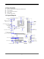
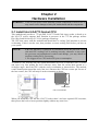
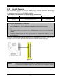
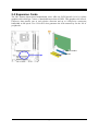
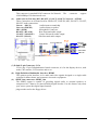
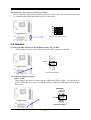
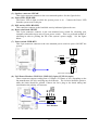
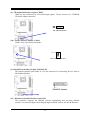
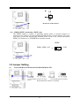
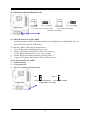
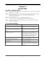
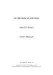
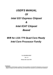
USER'S MANUAL
Of
IntelG41 Express and ICH7 Chipset
Based
M/B for LGA775 Quad Core Ready
Intel Core Processor Family
NO. G03-MI5G41SGM-F
Rev: 1.0
Release date: June 2009
Trademark:
* Specifications and Information contained in this documentation are furnished for information use only, and are subject to
change at any time without notice, and should not be construed as a commitment by manufacturer.
TABLE OF CONTENT
CHAPTER 1
1-1
1-2
1-3
1-4
CHAPTER 2
2-1
2-2
2-3
CONNCTORS, HEADERS & JUMPERS SETTING
CONNECTORS ..................................................................................................................... 7
HEADERS .............................................................................................................................. 10
JUMPER SETTING .............................................................................................................. 13
CHAPTER 4
4-1
4-2
HARDWARE INSTALLATION
INSTALL INTEL LAG775 SOCKET CPU ........................................................................ 5
INSTALL MEMORY............................................................................................................ 6
EXPANSION CARDS ........................................................................................................... 7
CHAPTER 3
3-1
3-2
3-3
INTRODUCTION OF INTEL G41 MOTHERBOARD SERIES
FEATURES OF MOTHERBOARD .................................................................................... 1
1-1.1 SPECIAL FEATURES OF MOTHERBOARD.................................................... 2
SPECIFICATION................................................................................................................... 3
ITEM CHECKLIST .............................................................................................................. 4
LAYOUT DIAGRAM ........................................................................................................... 4
USEFUL HELP
HOW TO UPDATE BIOS..................................................................................................... 15
TROUBLE SHOOTING ....................................................................................................... 15
Environmental Protection Announcement
Do not dispose this electronic device into the trash while discarding. To minimize pollution
and ensure environment protection of mother earth, please recycle.
ii
Chapter 1
Introduction of Intel G41 Motherboard Series
1-1
Features of Motherboard
The G41 Express and ICH7 chipset motherboard series are based on Intel G41 Express chipset
and ICH7 chipsets technology which supports the innovative 45nm and 65nm Quad-Core,
Dual-Core Intel® Core 2 Quad, Core 2 Duo processors, Intel® Pentium Dual Core, Intel®
Celeron Dual Core Conroe processors and Intel® Celeron 400 Conroe-L processors.
The G41 Express and ICH7 chipset Based motherboard series deliver the revolutionary levels
of performance enabling vivid, high-definition experiences and multi-tasking responsiveness
from state-of-the-art Intel dual-core and quad-core technologies through the high bandwidth
of dual channel DDRIII 800 / 1066MHz system memories which are expandable to 4 GB and
the next generation PCI Express interface for the latest AMD and NVIDIA graphics card .
The G41 Express and ICH7 chipset motherboard series are absolutely the ultimate solution for
game enthusiasts and applications, and it also meets the demanding usage of computing of
gaming, multimedia entertainment and business applications.
The INTEL G41 Express and ICH7 chipset motherboard series are embedded with ICH7
chipset of providing four serial ATA2 interface of 3.0 Gb / s data transfer rate for four serial
ATA devices.
The G41 Express and ICH7 chipset Based motherboard provides Gigabit LAN function by using
the Realtek RTL8111DL PCI Gigabit LAN which supports 10M / 100M / 1Gbps data transfer
rate. Embedded 8-channel ALC888 HD Audio Codec is fully compatible with Sound Blaster
Pro® standards that offer you with the home cinema quality and absolutely software
compatibility.
The G41 Express chipset based motherboard series offer one PCI-Express2.0 x16 by 16lane
graphics slots which get 7 times of bandwidth more than AGP8X. This graphics slot offers 8
Gbyte/sec data transfer rate at each relative direction and up to 16Gbyte/sec concurrent
bandwidth at full speed. Two 32-bit PCI slots guarantee the rich connectivity for the I/O of
peripherals.
Embedded USB controllers as well as capability of expanding to 8 of USB2.0 functional ports
delivering 480Mb/s bandwidth of rich connectivity, these motherboards meet the future USB
demands which are also equipped with hardware monitor function on system to monitor and
protect your system and maintain your non-stop business computing.
Some special features---CPU Thermal Throttling/ CPU Smart Fan/ CPU Vcore X-shift/3D
Audio in this motherboard are designed for power user to use the over-clocking function in
more flexible ways. But please be caution that the over-clocking may cause the failure in
system reliability. This motherboard provides the guaranteed performance and meets the
demands of the next generation computing. But if you insist to gain more system performance
with variety possibilities of the components you choose, please be careful and make sure to
1
read the detailed descriptions of these value added product features, please get them in the
coming section.
1-1.1 Special Features of motherboard
CPU Thermal Throttling Technology--- (The CPU Overheat Protection Technology)
To prevent the increasing heat from damage of CPU or accidental shutdown while at high
workload, the CPU Thermal Throttling Technology will force CPU to enter partially idle
mode from 87.5% to 12.5% according to preset CPU operating temperature in BIOS (from 40
℃ to 90℃). When the system senses the CPU operating temperature reaching the preset
value, the CPU operating bandwidth will be decreased to the preset idle percentage to cool
down the processor. When at throttling mode the beeper sound can be optionally selected to
indicate it is in working.
CPU Smart Fan--- The Noise Management System
It’s never been a good idea to gain the performance of your system by sacrificing its acoustics.
CPU Smart Fan Noise Management System is the answer to control the noise level needed for
now-a-day’s high performance computing system. The system will automatically increase the
fan speed when CPU operating loading is high, after the CPU is in normal operating condition,
the system will low down the fan speed for the silent operating environment. The system can
provide the much longer life cycle for both CPU and the system fans for game use and
business requirements.
CPU Vcore X-Shift--- Shift to Higher Performance
The CPU voltage can be adjusted up by 8 stages for the precisely over-clocking of extra
demanding computing performance.
3D Audio
OP with two-stage Butterworth filter and quadruple noninverting amplifier enhances bass
effect under the 100MHz range to perfect audio effect, brings you stunning shock experience
in video game, true-to-life simulated feeling when watching films and the greatest touch as
that in the concert.
2
1-2
Specification
Spec
Design
Chipset
Description
z
z
z
z
CPU Socket
LGA775
Memory Socket
Expansion Slot
z
z
z
z
z
z
z
Integrated Serial ATA2
Gigabit LAN
z
z
8CH-Audio
z
z
z
z
BIOS
z
z
z
z
Multi I/O
z
z
z
z
z
z
z
z
z
Micro-ATX form factor 4 layers PCB size: 24.5x21.0cm
Intel G41 Express Chipset
Intel ICH7 chipset
Support 45nm and 65nm Quad-Core, Dual-Core Intel® Core 2
Quad, Core 2 Duo processors, Intel® Pentium Dual Core,
Intel® Celeron Dual Core Conroe processors and Intel®
Celeron 400 Conroe-L processors 775-Land LGA Package
utilizes Flip-Chip Land Grid Array (FCLGA) package processor
Support FSB Frequency 1333MHz
DDR3 Module socket x 2
Support 2pcs DDRIII 800 /DDRIII 1066MHz DDRIII modules
expandable to 4 GB
Support Dual channel function
PCI-Express x16by16lane slot 1pcs
32-bit PCI slot x 2 pcs
The Intel ICH7 supports four Serial ATA ports provide 3.0
Gb/sec data transfer rate.
Integrated Realtek RTL8111DL PCI Gigabit LAN function.
Supports Fast Ethernet LAN function provide 10Mb/100Mb/
1Gb /s data transfer rate.
RealtekALC888 8-channel HD Audio Codec integrated
Support 8-channel 3D surround & Positioning Audio
Audio driver and utility included
Award 8MB DIP Flash ROM
PS/2 keyboard and PS/2 mouse connectors
S/PDIF Out connector x1
VGA connector x1
HDMI connector x1 (HDMI and DVI connector can not be used
at the same time)
DVI connector x1
USB2.0 port x 4 and headers x2
RJ45 LAN connector x1
Audio connectorx1 (8CH Audio)
SATA Connector x4
HDMI-SPDIF header x1
IR header
Serial Port headerx1
Parallel header x1
3
1-3 Item Checklist
5
5
5
5
5
Intel G41 Express and ICH7 chipset based Motherboard
User’s Manual
CD for motherboard utilities
SATA Cable
I/O Back Panel Shield
1-4 Layout Diagram
CPU Socket mPGA775
ATX 12V Power Connector
PS2 KB/Mouse
Port
SPDIF-OUT Connector
CPU FAN
DDRIII
DIMMx2
HDMI Connector
VGA and DVI Connector
ATX Power
Connector
KB/MS Power ON
Jumper (JP1)
USB Port
RJ45 Over
USB Port
SYSFAN1
COM Connector
Intel G41Express
Chipset
ATA100
IDE Connector
8-CH Audio Connector
Realtek RTL8111DL PCI –E
LAN Controller
PCI Express x16by16lane
ICH7 Controller
SYS FAN2
Serial-ATA2
Connector
(SATA1, 2, 3, 4)
32-bit PCI Slot
IR Connector
3D audio chip
Power Led &
Speaker Header
HDMI-SPDIF Connector
Front Panel Audio Parallel Connector
USB Port
ALC888 HD Audio CD Audio In
(USB2, USB3)
4
Front Panel
Connector
Chapter 2
Hardware Installation
WARNING!
Turn off your power when installing system components. Failure to do so
may cause severe damage to both your motherboard and the components.
2-1 Install Intel LGA775 Socket CPU
This motherboard provides a 775-pin DIP, LGA775 Land Grid Array socket, referred to as
the LGA775 socket supports Intel Pentium 4 processor in the 775 Pin package utilizes
Flip-Chip Land Grid Array (FC-LGA) package technology.
The CPU that comes with the motherboard should have a cooling FAN attached to prevent
overheating. If this is not the case, then purchase a correct cooling FAN before you turn on
your system.
NOTED!
1.Be sure that there is sufficient air circulation across the processor’s heat
sink and CPU cooling FAN is working correctly, otherwise it may cause
the processor and motherboard overheat and damage, you may install an
auxiliary cooling FAN, if necessary.
2. We suggest to use CPU under 65W power consumption.
LGA775
To install a CPU, first turn off your system and remove its cover. Locate the LGA775 socket
and open it by first pulling the level sideways away from the socket then upward to a
90-degree angle. Insert the CPU with the correct orientation as shown below. The notched
corner should point toward the end of the level. Because the CPU has a corner pin for two of
the four corners, the CPU will only fit in the orientation as shown.
Colden Arrow
CPU LGA775 Socket
When you install the CPU into the LGA775 socket, there’s no force required CPU insertion;
then presses the level to locate position slightly without any extra force.
5
2-2
Install Memory
The motherboards provide two 240-pin DDRIII DUAL INLINE MEMORY MODULES
(DIMM) slots for DDRIII memory expansion available from minimum memory size of 1GB
to maximum memory size of 4GB DDRII SDRAM.
Valid Memory Configurations of 2-DIMM Design Motherboard
Memory Module
240-Pin DIMM
PCS Total Memory
DIMM1
DIMM2
Total
DDRIII800/DDRIII1066
DDRIII800/DDRIII1066
System Memory (Max. 4GB)
X1
X1
2
1GB∼2 GB
1GB∼2 GB
1GB∼4 GB
Recommend DIMM Module Combination
1.
2.
One DIMM Module ----Plug in DIMM1
Two DIMM Modules---Plug in DIMM1 and DIMM2 for Dual channel function
For Dual channel Limited!
1.
2.
Dual channel function only supports when 2 DIMM Modules plug in either both DIMM1 &
DIMM2.
DIMM1 & DIMM2 must be the same type, the same size, and the same frequency for dual
channel function.
Generally, installing DDR SDRAM modules to your motherboard is very easy, you can refer
to figure 2-4 to see what a 240-Pin DDRIII 800/1066 SDRAM module looks like.
Figure 2-4
NOTE!
When you install DIMM module fully into the DIMM socket the eject tab should
be locked into the DIMM module very firmly and fit into its indention on both
sides
6
2-3 Expansion Cards
The G41 Express chipset based motherboard series offer one PCI-Express2.0 x16 by 16lane
graphics slots which get 7 times of bandwidth more than AGP8X. This graphics slot offers 8
Gbyte/sec data transfer rate at each relative direction and up to 16Gbyte/sec concurrent
bandwidth at full speed. Two 32-bit PCI slots guarantee the rich connectivity for the I/O of
peripherals.
PCI-E 2.0 x16 Slot
32-bit PCI Slot
7
Chapter 3
Connectors, Headers & Jumpers Setting
3-1 Connectors
(1) Power Connector (24-pinblock): ATXPWR
ATX Power Supply connector: This is a new defined 24-pins connector that usually
comes with ATX case. The ATX Power Supply allows using soft power on momentary
switch that connect from the front panel switch to 2-pins Power On jumper pole on the
motherboard. When the power switch on the back of the ATX power supply turned on,
the full power will not come into the system board until the front panel switch is
momentarily pressed. Press this switch again will turn off the power to the system
board.
** We recommend that you use an ATX 12V Specification 2.0-compliant power supply
unit (PSU) with a minimum of 350W power rating. This type has 24-pin and 4-pin
power plugs.
** If you intend to use a PSU with 20-pin and 4-pin power plugs, make sure that the 20-pin
power plug can provide at least 15A on +12V and the power supply unit has a minimum
power rating of 350W. The system may become unstable or may not boot up if the
power is inadequate.
ROW1 ROW2
PIN
ROW1 ROW2
(2)
Pin 1
Pin 1
20-Pin
24-Pin
ROW1
ROW2
1
3.3V
3.3V
2
3.3V
-12V
3
GND
GND
4
5V
Soft Power On
5
GND
GND
6
5V
GND
7
GND
GND
8
Power OK
-5V
9
+5V (for Soft Logic)
+5V
10
+12V
+5V
11
+12V
+5V
12
+3V
GND
ATX 12V Power Connector (4-pin block) : ATX12V
This is a new defined 4-pins connector that usually comes with ATX Power Supply. The
ATX Power Supply which fully supports AM2 processor must including this connector
for support extra 12V voltage to maintain system power consumption. Without this
connector might cause system unstable because the power supply can not provide
sufficient current for system.
(3)
PS/2 Mouse & PS/2 Keyboard Connector: KB
(4)
USB Port connector: USB port from USB1/ UL1
The connectors are for PS/2 keyboard and PS/2 Mouse
The connectors are 4-pin connectors that connect USB devices to the system board.
(5)
LAN Port connector: RJ-45 connector from UL1
8
This connector is standard RJ-45 connector for Network.
10M/100Mbps/1Gb data transfer rate.
(6)
The
connector
support
Audio Line-In, Lin-Out, MIC, RS-OUT, CS-OUT, SS-OUT Connector : AUDIO
These Connectors are 6 Phone-Jack for LINE-OUT, LINE-IN, MIC, RS-OUT, CS-OUT,
SS-OUT audio connections.
Audio input to sound chip
Line-in: (BLUE)
Audio output to speaker
Line-out: (GREEN)
Microphone Connector
MIC: (PINK)
Rear-Surround audio output
RS-OUT: (BLACK)
Center/ Subwoofer audio output
CS-OUT: (ORANGE)
Side-Surround audio output
SS-OUT: (GRAY)
VGA Connector
PS/2 Mouse
RJ-45
LAN
Line-IN
CEN/BASS
Line-Out
Surrback
T
Surround
SPDIF-OUT
Connector DVI ConnectorUSB Connector
PS/2 Keyboard HDMI Connector
MIC-IN
(7) D-Sub 15-pin Connector: VGA
VGA is the 15-pin D-Subminiature female connector; it is for the display devices, such
as the CRT monitor, LCD monitor and so on.
(8)
High-Definition Multimedia Interface: HDMI
This point-to-point interface is for audio and video signals designed as a single-cable
solution for home theater and consumer electronics equipment.
(9) SPDIF Out connectors: SPDIF_Out
The SPDIF output is capable of providing digital audio to external speakers or
compressed AC3 data to an external Dolby digital decoder. Use this feature only when
your stereo system has digital input function.
plugs at other end to the floppy drives.
9
(10) Serial-ATA Port connector: SATA1~SATA4
These connectors support the provided Serial ATA and Serial ATA2 IDE hard disk cable
to connecting the motherboard and serial ATA hard disk.
SATA3
SATA4
SATA2
SATA1
Serial-ATA1 & 2 Compatible Connectors
3-2 Headers
AUDIO
LINE2-JD
MIC2-JD
KEY
Audio-GND
Audio-JD
(1) Line-Out/MIC Header for Front Panel (9-pin): FP_AUDIO
These headers connect to Front Panel Line-out, MIC connector with cable.
2
10
Pin 1
Sense-FB
Lineout2-L
Lineout2-R
MIC2-L
MIC2-R
9
Line-Out, MIC Headers
(2) USB Port Headers (9-pin) :
USB2 / USB3
These headers are used for connecting the additional USB port plug. By attaching an
option USB cable, your can be provided with two additional USB plugs affixed to the
back panel.
VCC
-DATA
+DATA
GND
OC
VCC
-DATA
+DATA
GND
USB2/USB3
Pin 1
USB Port Headers
10
(3) Speaker connector: SPEAK
This 4-pin connector connects to the case-mounted speaker. See the figure below.
(4) Power LED: PWR LED
The Power LED is light on while the system power is on. Connect the Power LED
from the system case to this pin.
JW FP
PWRBTN
GND
PWRBTN
PWRLED
Pin 1
PWRLED
VCC5
PWR LED
(5) IDE Activity LED: HD LED
This connector connects to the hard disk activity indicator light on the case.
(6) Reset switch lead: RESET
This 2-pin connector connects to the case-mounted reset switch for rebooting your
computer without having to turn off your power switch. This is a preferred method of
rebooting in order to prolong the lift of the system’s power supply. See the figure
below.
(7) Power switch: PWR BTN
This 2-pin connector connects to the case-mounted power switch to power ON/OFF the
system.
SPEAK
VCC5
HDDLE
GND
RSTSW
NC
HDLED
RESET
GND
VCC5
Pin 1
SPKR
NC
Pin 1
System Case Connections
CPUFAN OUT
CPUFAN IN
GND
+12V
(8) FAN Power Headers: SYSFAN1, SYSFAN2 (3-pin), CPUFAN (4-pin)
These connectors support cooling fans of 350mA (4.2 Watts) or less, depending on the
fan manufacturer, the wire and plug may be different. The red wire should be positive,
while the black should be ground. Connect the fan’s plug to the board taking into
consideration the polarity of connector.
CPUFAN
1
4
1
SYSFAN2
SYSFAN1
1
3
FAN Headers
11
3
(9) CD Audio-In Headers (4-pin): CDIN1
CDIN are the connectors for CD-Audio Input signal.
CD-Audio output connector.
Please connect it to CD-ROM
CDIN
1
4
CD Audio-In Headers
(10) Serial COM Port Header: COM1
COM1 is the 9-pin block pin-header.
Pin1
Serial COM Port 9-pin Block
(11) Parallel Port header (25-pin): PARALLEL
The onboard parallel port header is a 25-pin connector for connecting devices such as
old-fashioned printer.
(12) IR infrared module Headers (5-pin): IR
This connector supports the optional wireless transmitting and receiving infrared
module. You must configure the setting through the BIOS setup to use the IR function.
12
GND
IRRX
IR
2
6
Pin 1
NC
VCC5
IRTX
5
IR infrared module Headers
(13)
HDMI_SPDIF_Out header: SPDIF_Out
The SPDIF output is capable of providing digital audio to external speakers or
compressed AC3 data to an external Dolby digital decoder. Use this feature only when
your stereo system has digital input function. Some of the VGA Card need connect
SPDIF_IN Connector, so its HDMI Port can make sounds.
SPDIF
HDMI_SPDIF_OUT
GND
1
2
3-3 Jumper Setting
(1)
Keyboard/Mouse/USB function Enabled/Disabled: JP1
JP1
JP1
1-2 Closed KB/MS/ USB Power ON Disable
(Default)
2-3 Closed KB/MS/ USB Power ON Enabled
Keyboard/Mouse & USB Power On Setting
13
(2) USB function Enabled/Disabled: JP2
JP2
JP2
1-2 Closed USB Power ON Disable (Default)
2-3 Closed USB Power ON Enabled
USB Power On Setting
(3) CMOS RAM Clear (3-pin): JBAT
A battery must be used to retain the motherboard configuration in CMOS RAM short 1-2
pins of JBAT to store the CMOS data.
To clear the CMOS, follow the procedure below:
1. Turn off the system and unplug the AC power
2. Remove ATX power cable from ATX power connector
3. Locate JBAT and short pins 2-3 for a few seconds
4. Return JBAT to its normal setting by shorting pins 1-2
5. Connect ATX power cable back to ATX power connector
Note: When should clear CMOS
1. Troubleshooting
2. Forget password
3. After over clocking system boot fail
1
1
JBAT
JBAT
3
1-2 closed
3
Normal (Default)
2-3 closed
CMOS RAM Clear Setting
14
Clear CMOS
Chapter 4
Useful Help
4-1 How to Upgrade BIOS
STEP 1. Prepare a bootable floppy disk. (You may make one by click START click RUN
type SYS A:
click OK)
STEP 2. Download upgrade tools and the latest BIOS files of the motherboard from official
website and then make a copy of it to your bootable floppy disk after
decompressing these files
STEP 3. Insert the disk into A: ,start your computer and then type in
“A:\xxxxxx.BAT”(xxxxxxx being the file name of the latest BIOS )
STEP 4. Type Enter to update and flash the BIOS. The system will restart automatically
when BIOS is upgraded.
4-2 Trouble Shooting
Problem
Solution
No power to the system to the all power light
don’t illuminate, fan inside power supply doesn’t
turn on.
System inoperative. Keyboard lights are on,
power indicator lights are lit, and hard drive is
spinning.
System doesn’t boot from hard disk drive, can be
booted from optical drive.
1. Make sure power cable is security plugged in.
2. Replace cable. 3. Contact technical support.
System only boots from optical drive .Hard disk
can be read and applications can be used but
booting from hard disk is impossible.
Screen message says “Invalid Configuration” or
“CMOS Failure”
Can not boot system after installing second hard
drive.
1. Back up date and applications files. 2.
Reformat the hard drive. Reinstall applications
and date using backup disks.
Review system‘s equipment .Make sure correct
information on is in setup.
1. Set master /slave jumpers correctly. 2. Run
SETUP program and select correct drive types.
Call the drive manufacture for compatibility with
other drives.
Using ever pressure on both ends of the DIMM ,
press down firmly until the module snaps into
places.
1. Check cable running from disk to disk
controller board. .Make sure both ends are
securely plugged in, check the drive type in the
standard CMOS setup. 2. Backing up the hard
drive is extremely important .All hard disks are
capable of breaking down at any time.
15