1
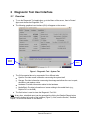
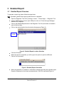
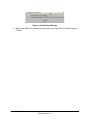
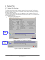
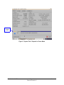
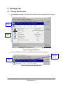
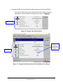
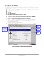
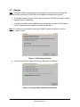
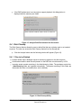
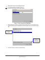
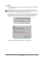
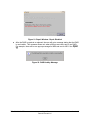
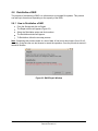
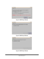
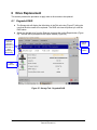
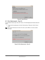
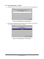
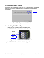
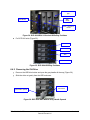
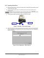
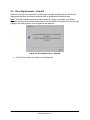
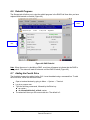
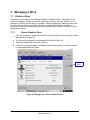
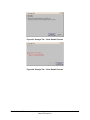
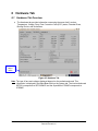
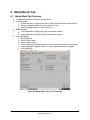
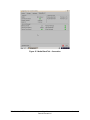
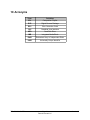
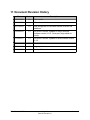
Diagnostic Tool
User Manual
Version 1.7
DTL.OM.000169.DRM
Page 1
Doremi Cinema LLC
Version 1.7
Software License Agreement
The software license agreement can be found at the following location:
http://www.doremilabs.com/support/cinema-support/cinema-warranties/
DTL.OM.000169.DRM
Page 2
Doremi Cinema LLC
Version 1.7
Table of Contents
1 Introduction............................................................................................................................. 4
1.1 Purpose............................................................................................................................. 4
1.2 Software Version................................................................................................................ 4
1.3 Contact.............................................................................................................................. 4
2 Diagnostic Tool User Interface..............................................................................................5
2.1 Overview............................................................................................................................ 5
3 Detailed Report....................................................................................................................... 6
3.1 Detailed Report Overview..................................................................................................6
4 System Tab.............................................................................................................................. 8
4.1 System Tab Overview........................................................................................................8
5 Storage Tab........................................................................................................................... 10
5.1 Storage Tab Overview.....................................................................................................10
5.2 Storage Tab Features......................................................................................................12
5.3 Analyze............................................................................................................................ 13
5.4 Disk Cleanup....................................................................................................................14
5.4.1 Files to be Deleted ....................................................................................................14
5.5 Repair ............................................................................................................................. 16
5.6 Reinitialize a RAID...........................................................................................................18
5.6.1 How to Reinitialize a RAID.........................................................................................18
6 Drive Replacement................................................................................................................ 20
6.1 Degraded RAID................................................................................................................ 20
6.2 Drive Replacement – Step 1/4.........................................................................................21
6.3 Drive Replacement – Step 2/4.........................................................................................22
6.4 Drive Replacement – Step 3/4.........................................................................................23
6.4.1 Identifying Which Drive To Replace...........................................................................23
6.4.2 Removing the Old Drive.............................................................................................24
6.4.3 Inserting a New Drive.................................................................................................25
6.5 Drive Replacement – Step 4/4.........................................................................................26
6.6 Rebuild Progress.............................................................................................................. 27
6.7 Adding the Fourth Drive ..................................................................................................27
7 Managing a Drive.................................................................................................................. 29
7.1 Disable a Drive.................................................................................................................29
7.1.1 How to Disable a Drive..............................................................................................29
8 Hardware Tab........................................................................................................................ 31
8.1 Hardware Tab Overview..................................................................................................31
9 Media Block Tab.................................................................................................................... 32
9.1 Media Block Tab Overview...............................................................................................32
10 Acronyms ........................................................................................................................... 34
11 Document Revision History...............................................................................................35
DTL.OM.000169.DRM
Page 3
Doremi Cinema LLC
Version 1.7
1 Introduction
1.1 Purpose
The purpose of this document is to provide guidance on how to use the Diagnostic Tool
application. The Diagnostic Tool application can be used with the following servers: DCP-2000,
DCP-2K4, DSV-J2, and ShowVault. This application provides information for each drive,
detailed reports, and allows the user to replace and rebuild a failed RAID.
1.2 Software Version
This document complies with DCP-2000, DCP-2K4, DSV-J2, and ShowVault software version
2.2.x and higher. If you cannot upgrade your software, contact Doremi for older versions of this
document.
1.3 Contact
If in need of help or assistance, please contact your nearest Doremi Labs Technical Support at:
USA
• 24/7 Technical Support line: +1-866-484-4004
• Technical Support Email: [email protected]
Europe
• 24/7 Technical Support line: +33 (0) 492-952-847
• Technical Support Link: http://support.doremitechno.org/ticketing
Japan
• Technical Support line: +044-966-4855
• Technical Support Email: [email protected]
Australia ~ China ~ India ~ Indonesia ~ Korea ~ Malaysia ~ New Zealand ~ Philippines ~
Singapore ~ Taiwan ~ Thailand
• Technical Support Email: [email protected]
DTL.OM.000169.DRM
Page 4
Doremi Cinema LLC
Version 1.7
2 Diagnostic Tool User Interface
2.1 Overview
•
To run the Diagnostic Tool application, go to the Menu of the server, then to Doremi
Apps. and choose the Diagnostic Tool.
•
The following graphical user interface (GUI) will appear on the screen:
Detailed
Report
Button
Quit
Button
Figure 1: Diagnostic Tool - System Tab
•
•
The GUI presented above is composed of four different tabs:
•
System: Provides overall information concerning the system itself
•
Storage: Provides information concerning the storage and allows the user to repair,
reinitialize, and replace a drive
•
Hardware: Provides information related to the hardware
•
Media Block: Provides information on issues relating to the media block (e.g.,
Dolphin DCI or the IMB)
The Quit button is used to close the Diagnostic Tool GUI.
Note: At any time, a detailed report can be generated by clicking the Detailed Report button
located on the bottom-left corner of the interface (Figure 1). Also, see the Section, “Detailed
Report,” for more information on this feature.
DTL.OM.000169.DRM
Page 5
Doremi Cinema LLC
Version 1.7
3 Detailed Report
3.1 Detailed Report Overview
To generate a report log, please follow the steps below:
Note: If possible, generate the report log while there is no playback.
•
Open the Diagnostic Tool GUI by clicking on menu → Doremi Apps. → Diagnostic Tool.
•
Insert a USB flash drive into an open USB port on the unit. Close the Ingest Manager
window when it appears.
•
Click on the Detailed Report button in the Diagnostic Tool GUI (this button is located in
each of the four tabs).
•
Click on the device/location from the window that pops up (Figure 2).
USB
Disk#0
Figure 2: Detailed Report Location Selection
•
Click the OK button.
•
When the report is completed, you will be given the option to eject the USB stick.
Choose Yes to proceed.
Figure 3: Detailed Report Generation
•
When the generation is complete, a confirmation message providing the complete report
file path is displayed on the screen as shown below: Click OK to proceed (Figure 4).
DTL.OM.000169.DRM
Page 6
Doremi Cinema LLC
Version 1.7
Figure 4: Confirmation Message
•
Remove the USB stick and send the report file to your local Doremi Technical Support
Contact.
DTL.OM.000169.DRM
Page 7
Doremi Cinema LLC
Version 1.7
4 System Tab
4.1 System Tab Overview
The System tab provides general information related to the server, such as: Serial Number,
Software/Firmware Version numbers, IP addresses, Product Name, Base Board, Watermark,
and Security Manager version.
The System tab also displays the status of the playback and the Composition Playlist UUID
(Figure 5). Whenever there is any associated KDM information for the CPL, this information will
also be displayed (Figure 6).
•
The System tab is illustrated below:
Playback is
in Play
mode
Figure 5: System Tab – Playback in Play Mode
KDM
information
when
applicable
Figure 6: System Tab – KDM Information
DTL.OM.000169.DRM
Page 8
Doremi Cinema LLC
Version 1.7
Playback
in Pause
mode
Figure 7: System Tab - Playback in Pause Mode
DTL.OM.000169.DRM
Page 9
Doremi Cinema LLC
Version 1.7
5 Storage Tab
5.1 Storage Tab Overview
•
The Storage tab consists of two sub-views: RAID Sub-View and Disk Sub-View (Figure
8).
RAID SubView
Disk SubView
Figure 8: Storage Tab Window
•
First, the RAID Sub-View lists all the RAID builds configured on the server.
Status shows
the health of
the disk
RAID SubView
Figure 9: Storage Tab- RAID Sub-View
DTL.OM.000169.DRM
Page 10
Doremi Cinema LLC
Version 1.7
•
Second, the DISK Sub-View lists all the disks configured in the selected RAID.
o
Click on a Disk from the list on the left part of the GUI and the information
pertaining to it will be displayed in the right part of the GUI (Figure 10 ).
DISK Sub-View
Figure 10: Storage Tab- Disk Sub-View
Note that this
information will
only be relevant
if the playback is
stopped
DISK Sub-View
Figure 11: Storage Tab Disk Sub-View For Units With Up To 4 Drives
DTL.OM.000169.DRM
Page 11
Doremi Cinema LLC
Version 1.7
5.2 Storage Tab Features
The RAID Sub-View lists all the RAIDs configured in the system and the information pertaining
to each, such as:
• An icon to show RAID status (green= healthy; amber= degraded/rebuild; red= missing)
• Array device name (/dev/mdX)
• Mount point
• Array size
• Array used disk space
• RAID status (healthy, degraded, rebuilding %, failed)
•
To analyze or repair a RAID, click on the Analyze or Repair buttons (Figure 12).
•
Analyze - To analyze a RAID performance and to free disk space.
•
Repair - To repair a degraded RAID. It attempts to sync a highlighted RAID that is
currently not part of the RAID. (please see Sections, “Drive Replacement” and
“Reinitialize the Raid” below).
•
Manage – To disable a possible faulty drive.
Analyze
Button
Orange Icon
indicates
degraded RAID
due to a failed
drive
Repair
Button
Manage
Button
Figure 12: Storage Tab Window With RAID Degraded
DTL.OM.000169.DRM
Page 12
Doremi Cinema LLC
Version 1.7
5.3 Analyze
Note: To Analyse a RAID, the playback must be stopped. Any use of the drives during this
process will give false alarms of the RAID and its hardware components being faulty.
•
The Analyze feature is used to check if the performance of a RAID is enough to support
playback without underflowing.
•
To analyze the RAID, click the RAID from the Storage tab, and then click the Analyze
button. A password will be needed to perform this operation.
Note: If in fact there is an issue that is causing the RAID to perform ineffectively, see the
Section, “Repair,” below.
Figure 13: RAID Analyze Window
•
If the test performance is good, the following dialog will be displayed:
Figure 14: Analyze Raid Performance Successful
DTL.OM.000169.DRM
Page 13
Doremi Cinema LLC
Version 1.7
•
If the RAID performance is not enough to support playback, this dialog below is
displayed and the reason(s) are listed:
Figure 15: Analyze Raid Performance Not Successful
5.4 Disk Cleanup
The Disk Cleanup feature allows the user to delete files that are not being used or not needed
anymore. The user can access the Disk Cleanup feature from the Storage tab.
•
Click the Analyze button and the following window will appear (Figure 16):
5.4.1 Files to be Deleted
• Orphan assets maps: database entries for assets not present on the disk anymore
• Unreferenced assets: asset files still present on the RAID but not referenced by a CPL.
• Incoming assets: assets remaining in the /data/incoming folder. The packages copied into
/data/incoming folder are ingested automatically. The assets remaining in this folder are
the assets that were not needed (thus, can be deleted).
Figure 16: Disk Cleanup Utility
DTL.OM.000169.DRM
Page 14
Doremi Cinema LLC
Version 1.7
•
Select Disk Cleanup from the Analyze window.
• The following window will appear (Figure 17):
Note: A password confirmation window might appear.
Figure 17: Disk Cleanup Scanning Window
•
Select the file(s) to delete by checking the associated check-box. The total amount of
space that will be gained is indicated on the bottom-right corner of the window (Figure
18).
Incoming assets
selected for
deletion
Total amount of disk
space
corresponding to
the selected file(s)
Figure 18: Disk Cleanup Window – Files Selected
•
Click the Ok button to delete the selected file(s).
DTL.OM.000169.DRM
Page 15
Doremi Cinema LLC
Version 1.7
5.5 Repair
•
To repair a degraded RAID or to completely reinitialize a RAID, press the Repair button
from the Storage tab.
Note: The Repair feature allows the user to repair a drive and or RAID by replacing a drive or
reinitializing the RAID. Please see the corresponding sections below for more information on
these features. See Sections, “Drive Replacement” and “Reinitialize a Drive.”
•
The system will give a pop-up message when the RAID is degraded. The message will
not appear when you are syncing the drive back in the RAID. This message will also
appear when the RAID is healthy and you do a reinitialize process (Figure 19).
Figure 19: Degraded RAID Alert Message
Figure 20: Repair Window - Repair Enabled
•
If the RAID cannot be repaired, the Repair button will be grayed out.
DTL.OM.000169.DRM
Page 16
Doremi Cinema LLC
Version 1.7
Figure 21: Repair Window - Repair Disabled
•
After the RAID is repaired or replaced, the user will get a message stating that the RAID
is now healthy. This message shows only when all drives are newly part of one RAID.
For example, there will be one pop-up message for MD0 and one for MD1. See Figure
22.
Figure 22: RAID Healthy Message
DTL.OM.000169.DRM
Page 17
Doremi Cinema LLC
Version 1.7
5.6 Reinitialize a RAID
The purpose of reinitializing a RAID is to reformat due to corrupted file systems. This process
can take up to three hours depending on the capacity of the RAID.
5.6.1 How to Reinitialize a RAID
•
From the Storage tab click on Repair.
•
The Repair window will appear (Figure 23).
•
Select the Reinitialize option and click continue.
•
The Reinitialize window will appear.
•
To Reinitialize, follow the two-step process.
Note: Completing this process results in a loss of data. A final count down begins (from 10 to 0
seconds), giving the user one last chance to cancel the operation. Once the process is started, it
cannot be undone.
Figure 23: RAID Repair Window
DTL.OM.000169.DRM
Page 18
Doremi Cinema LLC
Version 1.7
Figure 24: RAID Repair Window
Figure 25: RAID Repair Window
Figure 26: RAID Repair Window
DTL.OM.000169.DRM
Page 19
Doremi Cinema LLC
Version 1.7
6 Drive Replacement
This section presents the procedure to apply when a drive needs to be replaced.
6.1 Degraded RAID
•
The Storage tab will display the failed drive in the Disk sub-view (Figure 27) telling the
user that the drive needs to be replaced. The RAID sub-view will present you with the
RAID status.
•
Select the affected drive from the Disk sub-view and click on the Repair button (Figure
27). The user will be prompted to the Repair window (Figure 28).
Amber Icon
indicates
degraded
RAID due to a
failed drive, or
when
reinitializing or
re-synching
Analyze
Button
Repair
Button
Disk
Sub-View
Figure 27: Storage Tab - Degraded RAID
DTL.OM.000169.DRM
Page 20
Doremi Cinema LLC
Version 1.7
Figure 28: Repair Window
6.2 Drive Replacement – Step 1/4
From the Repair window (Figure 28), click Continue. The Disk Replacement Wizard window will
appear:
•
To start the drive replacement, click the Continue button. Otherwise, click the Cancel
button.
Note: This process will destroy the content of the drive (not the RAID). It cannot be undone
once it has begun.
Figure 29: Drive Replacement – Step 1/4
DTL.OM.000169.DRM
Page 21
Doremi Cinema LLC
Version 1.7
6.3 Drive Replacement – Step 2/4
•
Clicking the Continue button on the previous window will lead to the following window:
Figure 30: Drive Replacement – Start of Step 2/4
•
At the end of the unregistering process, the user will be prompted to continue (Figure
31). Click the Continue button to go to the next step.
Figure 31: Drive Replacement – End of Step 2/4
DTL.OM.000169.DRM
Page 22
Doremi Cinema LLC
Version 1.7
6.4 Drive Replacement – Step 3/4
In this step, the user will be prompted to insert a new drive at a specific position – corresponding
to the faulty drive's position. The faulty drive removal and new drive insertion procedure is
provided below:
Drive’s
Position
Figure 32: Drive Replacement – Start of Step 3/4
6.4.1 Identifying Which Drive To Replace
•
Identify which drive to replace by looking at the examples below:
•
For DCP-2000/DSV-J2 units fitted with horizontal drives (Figure 33):
Top
/DEV/SDA
Middle
/DEV/SDB
Bottom
/DEV/SDC
Figure 33: DCP-2000/DSV-J2 Horizontal HDD's Bay Positions
•
For DCP-2000/DSV-J2 units fitted with vertical drives (Figure 34):
DTL.OM.000169.DRM
Page 23
Doremi Cinema LLC
Version 1.7
SDA – located on the
right
LED Sticker
SDB middle
SDC – located on
the left
Figure 34: DCP-2000/DSV-J2 Vertical HDDs Bay Positions
•
For DCP-2K4 units (Figure 35):
SDA
SDB
SDC
SDD
Figure 35: DCP-2K4 HDD Bay Positions
6.4.2 Removing the Old Drive
•
Press on the HDD blue button and open the gray handle all the way (Figure 36).
•
Slide the drive out gently from the HDD enclosure.
Bottom HDD's
blue button
Bottom HDD's
gray handle opened
Figure 36: DCP-2000 HDD Bottom Grey Handle Opened
DTL.OM.000169.DRM
Page 24
Doremi Cinema LLC
Version 1.7
6.4.3 Inserting a New Drive
•
Before inserting the drive, press on the blue button to release the gray handle and open
it all the way until it clicks.
•
Insert the new drive all the way in the HDD enclosure at the same position as the
previous drive.
CAUTION: The drive must be inserted all the way inside the HDD enclosure BEFORE trying to
close the gray handle - otherwise the drive might not be plugged properly.
•
Close the gray handle by pushing it toward the HDD until it clicks.
Blue Button
Gray Handle
Figure 37: New HDD – Grey Handle Opening
•
When the new drive insertion process has been completed, the drive will automatically
become registered in the RAID and the user will be prompted to the Drive Registration
window (Figure 38).
Figure 38: Drive Registration – End of Step 3/4
DTL.OM.000169.DRM
Page 25
Doremi Cinema LLC
Version 1.7
6.5 Drive Replacement – Step 4/4
When the drive has been registered, a confirmation message indicating that the SATA drive
replacement has been successfully completed will be displayed as illustrated below:
Note: The RAID rebuilding process can take between 2-4 hours to complete. It will largely
depend on the amount of content that resides on the drive/HDDs. During this time, the user may
engage in any other process, such as ingestion and playback.
Figure 39: Drive Replacement – Step 4/4
•
Click the Close button to go back to the Storage tab.
DTL.OM.000169.DRM
Page 26
Doremi Cinema LLC
Version 1.7
6.6 Rebuild Progress
The Storage tab will allow you to view the rebuild progress in the RAID Sub-View after you have
replaced and inserted a new disk (Figure 40).
Rebuilding
Status
DISK SubView
Figure 40: RAID Rebuild
Note: When the server is rebuilding a RAID, a red icon will appear to indicate that the RAID is
being rebuilt. The status will read as unknown until the RAID is rebuilt (Figure 40).
6.7 Adding the Fourth Drive
The fourth drive cannot be added via the GUI. It must be added using a command line. To add
the fourth drive, follow the directions below:
•
•
•
•
Open a terminal window by going to Menu → System → Terminal.
Log in as a super user.
Type the following commands, followed by the Enter key:
◦ su <enter>
◦ sh /doremi/sbin/reinit_raid.sh <enter>
The wizard will show you the current raid size. The default is 3.
DTL.OM.000169.DRM
Page 27
Doremi Cinema LLC
Version 1.7
•
Figure 41: Terminal Window
The wizard will ask you how many drives you want to have. Enter the number 4 followed
by the Enter key (Figure 41).
IMPORTANT NOTE: This process is destructive. ALL CONTENT on all drives will be lost. You
can use either the Content Manager to export content that you need to keep onto a portable
HDD or ingest it onto another.
The raid will be partitioned and then the drives will be formatted. The partitioning process takes
a few minutes, but the formatting process takes about 4.5 hrs for 3x1TB drives. /dev/md0 will
show as rebuilding while /dev/md1 will show as degraded because /dev/md0 must be rebuilt
before /dev/md1 starts its rebuilding process. Watch the Diagnostic Tool to see the progress
bar. As soon as md0/md1 are healthy, you can start to ingest content again.
DTL.OM.000169.DRM
Page 28
Doremi Cinema LLC
Version 1.7
7 Managing a Drive
7.1 Disable a Drive
Presently, the only function of the Manage feature is to disable a drive. The purpose of this
feature is to disable (virtually) a drive that is performing at a very slow rate, which in turn, is
causing the RAID to perform slow. For example, a drive's performance speed may be too low,
but not at the rate where it has failed. Therefore, to regain the full speed of a RAID, it is
necessary to remove and replace that drive and rebuild the RAID. Please see Section, “Drive
Replacement,” above.
7.1.1
How to Disable a Drive
•
From the Storage tab, select the desired drive from the Disk sub-view and then click the
Manage button (Figure 42).
•
The user will be prompted to the Manage Disk window (Figure 43).
•
Select the Disable option and click Continue.
•
If the drive is already disabled, the Disable option will be grayed out and accompanied
by a message stating the reason.
Manage
Button
Figure 42: Storage Tab – Drive Disable Process
DTL.OM.000169.DRM
Page 29
Doremi Cinema LLC
Version 1.7
Figure 43: Storage Tab – Drive Disable Process
Figure 44: Storage Tab – Drive Disable Process
DTL.OM.000169.DRM
Page 30
Doremi Cinema LLC
Version 1.7
8 Hardware Tab
8.1 Hardware Tab Overview
•
The Hardware tab provides information concerning the server itself, such as:
Temperature, Voltage, Fans, Error Correction Code (ECC) status, Decoder Errors,
Booting Device, and Underflows.
Detailed
Report
Button
Figure 45: Hardware Tab
Note: The type of fans and voltages displayed depend on the motherboard used. This
information is displayed in the Base Board field on the System tab. The Intel motherboard
SE7221 corresponds to SE7221BK1E and the SuperMicro X7SB4/E corresponds to
X7SB4/E.
DTL.OM.000169.DRM
Page 31
Doremi Cinema LLC
Version 1.7
9 Media Block Tab
9.1 Media Block Tab Overview
•
•
•
•
The Media Block tab is divided into three sections:
Projector Model:
• Connection Status: Displays the status of the connection with the media block
• Dowser: Displays whether or not the dowser is open
• Lamp: Displays whether or not the lamp is on
Media Decoder:
• Video Watermark: Displays the type of watermark present
• Audio Watermark: Displays the type of watermark present
Security Manager:
• Blackout Mode
• Service Door Status
• Service Door Armed
• Physical Marriage: Displays whether or not the physical marriage is operational
• Logical Marriage: Displays whether or not the logical marriage is engaged
• Active Marriage:
Figure 46: Media Block Tab – No Connection
DTL.OM.000169.DRM
Page 32
Doremi Cinema LLC
Version 1.7
Figure 47: Media Block Tab - Connection
DTL.OM.000169.DRM
Page 33
Doremi Cinema LLC
Version 1.7
10 Acronyms
DTL.OM.000169.DRM
Term
Definition
CPL
Composition Playlist
DCP
Digital Cinema Package
ECC
Error Correction Code
GUI
Graphical User Interface
HDD
Hard Disk Drive
IMB
Integrated Media Block
RAID
Redundant Array of Independent Disks
UUID
Universally Unique Identifier
Page 34
Doremi Cinema LLC
Version 1.7
11 Document Revision History
Date
Version
12/05/2006
1.0
First version.
03/17/2009
1.1
All sections revised.
01/13/2010
1.2
New storage tab GUI and other section revisions and
additions.
12/08/2010
1.3
All sections revised. Updated to comply with new
software version 2.0.10. "Acronyms" page added for
clarity.
11/02/2011
1.4
All sections revised. Updated to reflect software version
2.2.2.
01/24/2012
1.5
Contact information revised.
07/20/2012
1.6
Logo updated.
08/03/2012
1.7
Section 6.7 added.
DTL.OM.000169.DRM
Description
Page 35
Doremi Cinema LLC
Version 1.7