1
Front and Rear Layout of the Multiplexer CCT286
CCT286d2
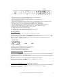
Front view of the multiplexer
The on/off switch is on the far left hand side
The camera select switches are shown marked 1-9
The function switches for Quad, Freeze, Playback, Auto etc are on the right hand side
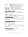
CCT286d4 Rear view of the multiplexer
The BNC sockets on the top row left side are camera inputs 1-9
The BNC sockets underneath them are the video outputs
There is a monitor output socket (labelled 7 on diag. CCT286d4)
VCR in and out sockets (labelled 8 and 9 on diag. CCT286d4)
S-VHS in and out sockets (labelled 10 and 11 on diag. CCT286d4)
2 15 way ‘D’ type connectors:
1 labelled 12 (Remote Control) on diag. CCT286d4
1 labelled 13 (Alarm Contacts) on diag. CCT286d4
To the right of these are the Mains fuse and the Mains input connector (IEC or ‘Kettle lead’)
System Q Ltd. The Green, Hasland, Chesterfield, S41 0LJ
2