1
What to check for on unpacking the Multiplexer.
Multiplexer with the correct number of camera inputs as ordered.
Instructions for Installation and Operation of the multiplexer
An IEC power lead
Adapter lead (if ordered!) to connect to the Hitachi TLR. Ordered as a separate item.
Connecting to the Multiplexer
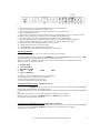
CCT286d4
The connections refer to diagram CCT286d4 above.
It is possible to connect up to 9 cameras to the multiplexer. They are connected to the top row of BNC sockets
marked 1-9. It is possible to ‘loop’ the video through the multiplexer by connecting equipment such as
monitors to the output BNC sockets under the input BNC socket on the multiplexer. This in effect Bypasses
the multiplexer and can be used to monitor the video input directly from the cameras.
The monitor connects to the BNC socket labelled MONITOR marked as (7) on the diag. above.
If using a Time Lapse or standard VCR connect the input of the VCR to the output VCR BNC socket on the
multiplexer, labelled VCR and is the bottom BNC socket labelled (9) on the diagram above.
The output from the VCR connects to the VCR input BNC socket on the multiplexer.
It is essential to connect the VCR or TLR this way or it will not be possible to use the multiplexer for
viewing images on the tape being replayed.
When the tape is replayed the multiplexer can be used to view images in single screen mode, multi-screen
mode (Quad or 9 images) or to automatically scan through the screens.
There is also the facility to connect a VCR using S-VHS connectors marked 10 and 11 on the diagram.
The socket marked Remote Control on the multiplexer and labelled 12 is for a Remote Control Keypad that is
available separately. This connector is a 15 way ‘D’ type socket.
The next socket marked Alarm input/output and labelled 13 on the diagram (the top row of pins) is for alarm
sensors. It is possible to have alarm sensors on video sockets 1-8, 9 is not alarmed. (These pins are held at
TTL level 5 volts and to activate they can be linked to 0 volts).
On the bottom pins of the connector labelled 14 is the Trigger input (special function for linking to the Hitachi
TLR see section 2 page 5); the other pins are clean or dry relay contacts to provide an output to external
devices in alarm conditions. (These are standard relay contacts Common, N/O and N/C).
The connector labelled 15 is the mains fuse holder.
The connector labelled 16 is the mains input connector, this is an IEC connector (kettle lead type)
System Q Ltd. The Green, Hasland, Chesterfield, S41 0LJ
3