1
This is the text that is displayed on the full screen shot of the selected cameras. The text in the speech marks
“*” can be edited as required. There are only 8 characters allowed remembering that full stops etc count as a
single character.
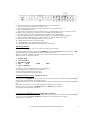
When CH1 is flashing press key 5 or 6 to change to a different channel number.
Pressing key 4 will move the cursor across to the text in speech marks. Highlight the character to be changed
and then press key 5 or 6, the cursor now moves to the lower section of the display. By using keys 1, 2, 3 or 4
replacement characters can be selected, press the key 5 or 6 to change the character and repeat until all the
text has been replaced as required.
Pressing key 7 will change to a different menu, pressing 9 exits from the setup menus.
Alarms/Loss Recall Screen
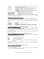
Pressing the LIST key shows the Alarms/Loss screen. This consists of 16 pages of 8 lines with date and time
information including channel number and what the alarm event was. (L = loss of video, A = alarm)
Date
Time Ch (channel)
- (event = L/A)
Use keys 5 and 6 to scroll up or down through the screens.
Pressing key 8 erases the stored information on the displayed screen.
When all the information has been viewed or erased pressing the LIST key again exits from the menu.
Alarm Contacts.
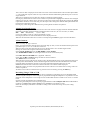
This is a 15 way ‘D’ type connector.
Pins 1~8 correspond to the cameras and are set at TTL high (5 volts). To activate an alarm these inputs can be
grounded to pin 13, 14 or 15 on the same connector.
When an alarm event takes place the full screen is displayed for a user variable length of time.
Settings to check when using the alarm feature of the unit:
In the VCR & ALARM menu set the REC MODE: to TLV.ALARM
The ALARM RELAY TIME sets the length of time the event is monitored (0-99)
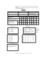
In the REC MON LOAD ARM menu: (Appendix 1 Menu 4)
Check that the REC and MON settings are ON for relevant cameras.
The ARM should be set for N.O.
When the tape is being replayed view alarm events in the Quad display, these can be selected for full screen
viewing in the normal manner, the non-alarmed segments will not be recorded. Should there be an alarm
triggered during playback the relevant screen will be automatically displayed for the set time.
Should there be more than one alarm event then alternate screen shots will be displayed.
When the system reverts back to playback mode a screen will have to be selected for viewing, either one
camera or Quad etc.
All alarm events will be recorded in the log, which can be accessed by pressing the LIST key.
Recording Using a TLR or VCR
The VCR being used must be connected as shown in diagram() if the images are to be manipulated and
viewed using the multiplexer. When images are played back through the multiplexer it is possible to use the
functions on the multiplexer to view single screens of individual cameras or multi screen views i.e. 9-screen
mode.
In menu 2 set the VCR OUTPUT to CONTINUOUS.
When using the multiplexer with a System Q supplied Hitachi TLR and adapter cable set the VCR OUTPUT
in menu 2 to TIMELAPSE. Set REC MODE to TLV-NORMAL if no alarms are used.
Select the VCR input, either BNC or S-VHS according to the connections being used. (refer to diag.
CCT286d)
System Q Ltd. The Green, Hasland, Chesterfield, S41 0LJ
6