1
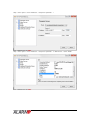
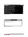
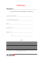
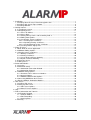
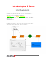
Introducing the IP Server
Initial Requirements
Com Ports:- ( Representative Port Numbers Only....Replace with your own Port Numbers…..)
Sign up Port = 17001 / Same as Set-up Port & Parameter Port.
SSL Port / (Polling Port) = 17000 / Same as Alarm Servers Port in Parameter Server Options.
UDP Port = 17002
Automation Port = 1003
IP Addresses = WAN 192.168.0.1 / LAN10.10.10.01 / ( Wide area network / Local area network ).
( Representative IP Addresses Only....Replace with your own IP Addresses…..)
1
Ports and IP as displayed on relevant screens…..
During Alarm IP Wizard
Setup > Server options
Setup > Server options > Automation PC
2
Setup > Server options > Server Parameters > Setup Server parameters 1
Setup > Server options > Server Parameters > Setup Server parameters 1 > Alarm Servers > Server A Path 1
3
Pyronix IP Polling Server Screen
Automation module > Start
4
YOUR Details…..
Site Name =_______________________________
Insert your ‘Port settings’ and ‘IP Address’s’ for Reference
Sign up Port / Setup Port / Parameter =__________________________________________________
SSL Port / Polling Port / Alarm servers Port = ____________________________________________
UDP Port = ________________________________________________________________________
Automation Port = 1003 / ______________________________________________________________
IP Address =
WAN = ______________________________________________________________
LAN = ______________________________________________________________
NOTES:-
Print / Save Page 5 to Use / Store…..
5
1. Installation .................................................................................................................... 1
1.1 Installing Alarm IP Server From www.pyronix.com..................................................... 7
1.2 Installing SQL Server Express 2008 ......................................................................... 8
1.3 Installing DESKEY................................................................................................... 9
2. Getting Started............................................................................................................ 10
2.1 Launching the Server ............................................................................................ 10
2.2 Configuring Server ................................................................................................ 11
2.2.1 Server IP Address .......................................................................................... 11
2.2.2 Server Ports................................................................................................... 12
2.2.3 Setting Primary Path 1 and Secondary Path 2 .................................................. 13
2.2.4 Polling Path Options....................................................................................... 14
2.2.5 Creating the Server Certificates....................................................................... 15
2.2.5.1 Creating New Certificates......................................................................... 15
2.2.5.2 Importing Existing Certificates .................................................................. 16
2.2.5.3 Creating Backups of the Certificates ......................................................... 16
2.2.6 Creating another Signup Port .......................................................................... 17
3. Alarm IP Server .......................................................................................................... 18
3.1 Main Alarm IP Server Application ........................................................................... 18
3.2 Additional Polling Options...................................................................................... 19
3.3 Changing Server Certificates ................................................................................. 20
3.3.1 Backup Certificates......................................................................................... 20
3.3.2 Viewing Certificates........................................................................................ 20
3.3.3 Create New Certificate Authority...................................................................... 21
3.3.4 Import Certificate Authority.............................................................................. 21
3.4 Parameter Server.................................................................................................. 23
3.5 Polling Server ....................................................................................................... 24
4. Automation Module ..................................................................................................... 25
4.1 Overview .............................................................................................................. 25
4.2 Automation Setup.................................................................................................. 25
4.2.1 Automation Connection Method....................................................................... 26
4.2.2 Automation Protocol ....................................................................................... 26
4.3 Additional Setup Options ....................................................................................... 27
4.3.1 Heartbeat Timer and Server Numbers.............................................................. 28
4.3.2 General Options............................................................................................. 28
4.3.3 Additional Ademco 685 Options....................................................................... 29
4.4 Connecting MXMON to the IP Server ..................................................................... 30
4.5 Running Multiple Automation Modules.................................................................... 31
5. UDL Server................................................................................................................. 34
5.1 Installing UDL Server............................................................................................. 34
5.2 Setting up UDL Server........................................................................................... 34
5.2.1 UDL Server Options........................................................................................ 34
5.2.2 Alarm IP Server Options ................................................................................. 36
6. Help ........................................................................................................................... 37
7. Further Information and Tutorials ................................................................................. 38
7.1 An Example Network............................................................................................. 38
7.1.1 Static IP Address............................................................................................ 38
7.1.2 Port Forwarding.............................................................................................. 40
7.1.3 Opening Ports................................................................................................ 41
7.2 Glossary ............................................................................................................... 42
6
1. Detailed Installation
1.1 Installing Alarm IP Server From www.pyronix.com
Unzip the file Pyronix Alarm IP Server.zip. The directory Pyronix Alarm IP Server is
created. Run the file setup.exe. This will install the software.
During the installation the following software may also be installed.
.NET Framew ork 3.5 SP1
Please Note: After installing .NET Framework 3.5 a reboot of the PC will be required. If you
have a previous version of the IP Server installed this will run when the PC is rebooted,
please close this software before continuing with the install. You may also get an installation
failure and the install will exit, to correct this just rerun setup.exe and the installation will
continue.
Press Accept if this software is required. Please ensure that there is an active internet
connection as this software will be downloaded and installed from Microsoft. The installation
of this software is automated and requires no user interaction.
Select the installation Folder to install the software. To avoid any compilation use the default
folder provided however the software can be installed in any location. Press Next > to
continue.
7
Press Close to complete the installation.
1.2 Installing SQL Server Express 2008
Microsoft SQL Server Express 2008 can be downloaded from the following web address:
http://www.microsoft.com/en-us/download/details.aspx?id=23650
Full installation instructions are available on this web site.
8
1.3 Installing DESKEY
The Alarm IP Server requires a DESKEY software protection dongle to be inserted in to the
PC at all times. This device comes as either a Parallel or USB device.
You can install the latest version of the driver for this device from:
http://www.pyronix.com/download-pip.php
Press Next > followed by Finished.
9
2. Getting Started
The complete IP Server includes 5 pieces of software. Each one has its own icon on the
desktop.
In order to sign up and receive events from a panel the Parameter and Polling Server
software must be running.
In order to report missed polling events the Alarm IP Server software must be running.
In order for the Alarm IP Server to report software to an automation computer the Automation
software must be running.
Alarm IP Serv er
This application allows the viewing of the panels on the server and also controls all the
settings for the other applications. This application must be running in order for the server to
report missed polling events.
Alarm IP Parameter Serv er
This application sends out all the parameters to panels that connect. This application must
be running in order for panels to register with the server successfully.
Alarm IP Polling Serv er
This application receives all the polling and event reporting information from connected
panels.
Alarm IP Automation
This application sends out all the received events from panels to a piece of Automation
software like MXMON.
Alarm IP UDL Serv er
The UDL Server provides a link between the panel and the Insite Upload/Download software
from Castle Care-Tech.
2.1 Launching the Server
This section will describe how to set up a single server solution for the Alarm IP Server.
However the best configuration of the server is for there to be 2 servers on the system which
provided backup for each other, section 6 will describe how to setup the 2 nd server.
To start the software double click on the Pyronix Alarm IP Server icon on the desktop.
The software will start with the screen shown below. If the server has already been
configured a countdown of 15 seconds will begin and the server will start automatically.
10
2.2 Configuring Server
Press Setup Server to be taken through a series of screens to enter information required to
run the server software.
2.2.1 Server IP Address
The first screen will ask you to confirm the IP address information that the software has
detected.
11
The options presented are as follows
Use Local Area Netw ork IP Address (LAN IP) Only – With this option selected even if you
have an internet connection, only panels within the local network will be allowed to poll the
server.
Use Internet IP Address (WAN IP) Only – With this option selected only panels connecting
to the server from an internet connection will be allowed to poll the server.
Use both LAN and WAN IP – This is the recommended setting, with this panels from both
the LAN and WAN will be able to connect. This will allow customer panels on the internet to
poll the server but also allow local panels to connect for testing purposes. If you have a panel
to connect on your LAN you use the LAN IP address of the server, but panels outside of the
LAN on the internet use the WAN IP address.
Note, if you do not have an internet connection then only the LAN IP option will be displayed.
2.2.2 Server Ports
Before a panel can poll and report events to the server it has to sign up to the server and
receive a set of parameters so that it knows where to report to.
The Setup Wizard sets up the server for single Signup Port. The default is 17001. You can set
up to 16 different signup ports using more advanced options within the software. Multiple
signup ports are used to allow panels with different mobile phone networks to connect to the
server, it can also be used to set up different grades or polling rates to the server.
The Polling port which by default is 17000 is used by the panels to poll and send events to
the server once it has been signed up to your server.
Note that these ports can be change to suit your network.
12
2.2.3 Setting Primary Path 1 and Secondary Path 2
Path 1 is typically Internet or Network (WAN or LAN) and Path 2 is GPRS.
If GPRS is selected the SIM Card details need to be entered. A list of known GPRS server
details from around the world are included, if the provider required isn’t in the list then enter in
the details. It is through multiple Sign Up ports (up to 16) that different SIM Cards can be
accommodated in the server.
13
2.2.4 Polling Path Options
Polling Rate
How often the alarm system contacts the computer specified with ‘keep-alive’ or ‘heartbeat’
messages. Value is delay between contacts in seconds. A value of zero indicates these
messages are not to be sent.
Advanced Options
Retry
Retry timeout in seconds for the computer specified. When the alarm system reports an
event, and it does not get a response from the computer within the time given in this
parameter, it will re-send the event.
Timeout
Failure timeout in seconds for the computer specified. When the alarm system reports an
event, and it does not get a response indicating successful processing of the event within the
time given in this parameter, it will assume failure and try another computer if available.
Note : The value specified in Failure should be higher than the value in Retry in order to
allow multiple retries of an event.
Backup Poll
In the event of the main polling path going down the panel will revert to this value for the
polling rate.
14
2.2.5 Creating the Server Certificates
The Transport Layer Security (TLS) and its predecessor, Secure Sockets Layer (SSL),
provide secure communications over the internet.
It is this protocol that is used by all secure web pages like shopping sites and banks. When
you visit some websites to you may notice that the web address has https:// in the url, this
means you have a secure connection to the website. The Alarm IP Protocol also uses
TLS/SSL and digital certificates to provide the most secure connection between the control
panel and server available.
The control panel has built into it a certificate provided by the manufacturer, at a later stage of
this installation this certificate will be installed.
When creating certificates using the setup wizard there are 2 options, the option to Create
New Certificates or Import Existing Certificates.
2.2.5.1 Creating New Certificates
Use this option when creating a new server. By default the name for the certificate is “Pyronix
IP Server”, this can be changed to something different but the name must not exist in the
certificate store of the computer.
Press Create to make the certificate.
If the certificate has been created then the following message is displayed, press OK and
then Next >> and move onto the section 2.2.5.3.
15
2.2.5.2 Importing Existing Certificates
Use this option is you already have a certificate file. This file must be in PKCS #12 format,
typically this will have a .pfx file extension.
Use Find File to load the file from the computer and provide the password from the file. This
certificate will be used to create the certificates for use with the server.
2.2.5.3 Creating Backups of the Certificates
After creating the certificate it is important to make a backup of the certificate. This will allow
the ability to copy the certificate to a new computer recreate the server so that panels signed
up to the server can continue to poll uninterrupted.
Creating a backup is the most important part of setting up the server.
To back up the certificate complete the following steps on the screen shown on the next page.
1. Enter a password for the certificate. Remember this password as it will be needed to
load the certificate.
2. Press Create Backup
3. Copy the file from the location shown onto another device such as a CD, DVD or
USB. It might be an idea to create multiple copies.
4. Keep this copy of file safe, and do not disclose it to anyone.
On the next page is a screen shot showing the information provided by the software.
16
2.2.6 Creating another Signup Port
After creating the certificates a number of information screens are displayed and then more
sign ups ports can be created.
The idea for this is that multiple SIM Cards can be supported in the panels connected to the
server as not all panels will potentially use the same mobile phone operator.
Press Yes to create another sign up port.
17
3. Alarm IP Server
3.1 Main Alarm IP Server Application
The Main Application controls all the programming for the Server and does all the reporting of
missed polling. A Deskey is required to be inserted into the PC in order for missed polling to
be reported.
To run this application, double click on the Pyronix Alarm IP Server icon on the desktop.
Panel Information
Enter in a valid Panel ID to view the polling information for that panel. The Panel ID is in the
format 00-000000-0.
Included in this is information for the 2 paths, the panel type, and the last 50 received alarm
events. This information is in the raw reporting format, to view decoded use Automation
software.
Also shown is the Parameter Server used by the panel, to get the panel to contact that server
press Contact. To view the parameters for that server press View , please note that the
parameters may have been changed since the panel signed up so they may not be the same
values as sent to the panel.
When an IPCOMM is used the Connection Information and Outputs options become
available. The IPCOMM has 3 outputs and these can be controlled from this application.
A panel can be deleted from the server by using the Delete tab. To delete the panel the
panel ID must be re-entered to confirm that this is the panel to be deleted.
18
3.2 Additional Polling Options
Accessed using the Server Options menu, information about missed polls and sign up
procedure can be selected.
Number of Missed Polls Allow ed
The server continually checks for any panels that have stopped sending poll
messages. There could be a number of reasons why a panel has stopped sending events
like network lag or the internet connection on the panel is down. This option controls how
many times a poll is missed before it is reported the automation computer.
Missed Polling Ev ent
The server can output to an automation PC the fact that a panel has stopped polling. The
server sends this message as a user defined reporting format message. Contact ID or SIA
can be selected as the format to use.
Contact ID
Enter the event number from 000 to 999, the same number is used for the new event and the
restore. Take care not to use a number already assigned. Note that if SIA CIS automation
protocol is used then this event is automatically converted into the equivalent SIA Level 1
reporting event.
SIA Level 1
Enter the event code to use for both the new event and the restoral. SIA codes are in the
range AA to ZZ. Take care not to use a code already assigned.
Important Note: Contact ID only uses 4 digit account codes so if the account codes being
programmed in the panels are less are greater than this then only use SIA Level 1 for
reporting the Missed Polled events.
Require ARC Account to sign up
As part of the sign up procedure on a control panel there is the option to enter in an account
code to use. Select this option to deny access to any control panel trying to sign up with one.
Do not allow same ARC Account
If more than one panel has the same account code it can make identification of control panels
difficult. To prevent this situation panels connecting with an account code already in use can
be blocked by selecting this option.
19
3.3 Changing Server Certificates
The certificates used on the server can be viewed, changed and backed up using the
Certificates menu option.
3.3.1 Backup Certificates
It is important to create a backup of the server certificate.
Enter a password and press Create Backup.
A backup file is created in the “My Documents” folder of the computer. The software will
display the location of the file.
It is important that this file is then copied to another device, either CD, DVD, USB Device or
another computer and kept in a safe place. Also remember the password used.
3.3.2 Viewing Certificates
The currently installed certificates can be viewed using this option.
The following information is displayed.
Name
Issued By
Valid From
Valid To
Serial No
Thumbprint
Private Key
20
3.3.3 Create New Certificate Authority
It is dangerous to create a new certificate authority once the software has been installed,
however it can be done from within the software using the procedure below.
Enter a Name and Password for the new CA and press Create.
The new CA will be created, a backup of the CA will be created and the following message
displayed.
3.3.4 Import Certificate Authority
It is dangerous to create a new certificate authority once the software has been installed,
however it can be done from within the software using the procedure below.
21
Press Find to locate the .pfx file on the computer and enter in the Password for the file.
With the file selected press Import and the file will be imported into the software and new
certificates created.
Restart the software to use the new Certificates.
Please note any panels connected the server will be unable to connect.
22
3.4 Parameter Server
The Parameter Server controls the giving out of all polling parameters to panels that use the
Alarm IP Server.
The software runs in a command window and is therefore easy to close by mistake. Do not
unless it is necessary close this window as this will stop the server from running and will not
allow any panels to connect to the server.
To program the settings for this software use the Main Alarm IP Server application, see the
Server Options and Server to Panel Parameters sections of this help file. When changes are
made to the settings of this software close and restart the software to apply the new settings.
To run this application, double click on the Pyronix Alarm IP Parameter Server icon on the
desktop.
The application displays the IP Addresses that the PC is using. This information can be used
when entering the IP Address information into the parameter options.
The application contacts pyronix.com to return the Internet IP address of the PC if it is
connected the internet. This feature can be turned off by deselecting the Contact
pyronix.com at start up to show Internet IP Address option in the Options screen of the
Main Application.
23
3.5 Polling Server
The Polling Server receives all the polling and reporting information for the panels connected
to the Alarm IP Server.
The software runs in a command window and is therefore easy to close by mistake. Do not
unless it is necessary close this window as this will stop the server from running and will not
allow any panels to connect to the server.
The application displays the IP Addresses that the PC is using. This information can be used
when entering the IP Address information into the parameter options.
The application contacts pyronix.com to return the Internet IP address of the PC if it is
connected the internet. This feature can be turned off by deselecting the Contact
pyronix.com at start up to show Internet IP Address option in the Options screen of the
Main Application.
24
4. Automation Module
4.1 Overview
The Automation Module allows for events received by the server to be passed onto a
compatible automation computer. At present Surgard, Silent Knight Expanded, Ademco 685
and SIA Computer Interface Standard protocols are supported and can be sent over a TCP or
serial connection.
Connection Information
This will show connection information.
Automation Computer Status
This icon will be one of the following colours
Grey – No automation software connected
Green – Automation software connected and working
Red – Automation software error
Deskey Status
In order for events for the sent to the automation software a Deskey dongle must be inserted
into the PC. This device is available from Pyronix. This icon will be one of the following
colours
Green – Deskey inserted and working.
Red – No Deskey installed.
4.2 Automation Setup
When launched the software displays an option to run the software or enter the setup wizard.
25
4.2.1 Automation Connection Method
The Automation Module can connect using TCP or a Serial Cable.
Netw ork (TCP)
If the automation PC supports a TCP connection enter the port to use
Serial Cable
The server can output data over a serial link to an automation PC. Select the Port (all
available serial ports that are detected are displayed), Baud Rate, Parity, Data Bits, Stop Bits
and Flow Control.
Please note that the server has the ability to receive events over the internet faster than it can
send them to the automation PC over a serial link.
The cable to use is shown in the diagram below.
4.2.2 Automation Protocol
26
The server can output in multiple formats to an automation PC including Silent Knight
Expanded, SIA CIS, Surgard and Ademco 685.
The supported automation protocols are
Pyronix Expanded and Silent Knight Expanded
These emulate the Silent Knight 9500 and 9800 receiver protocols.
SIA CIS
This outputs data using the SIA CIS (Computer Interface Standard) June 1990 protocol.
Surgard MLR2
This emulates the Surgard MLR2, SLR and MLR2E receivers.
Surgard MLR2000
This emulates the Surgard MLR2000, System-II and System-III receivers.
Ademco 685
This emulates the Ademco 685 receiver and protocol. See section 4.3.3 Additional Ademco
685 Options for compatibility options for this protocol.
For more information on these protocols view the help file that is available when running the
Alarm IP Server and described in Section 6 of this manual.
For a complete description of each protocol please view the relevant manuals for the
receivers and protocols provided by the manufacturers.
4.3 Additional Setup Options
More advanced options for the Automation Module are accessed using the Setup menu within
the software.
27
4.3.1 Heartbeat Timer and Server Numbers
These can accessed through the Port Settings of the Setup Automation PC menu option.
On these screen you can also change the Connection Method and Protocol which were
described previously.
Heartbeat Timer
A message can be sent to the PC to ensure that the link between the two is still
working. Enter in a value in seconds for the frequency of this. A value of 0 (zero) indicates
no heartbeat is to be sent.
Serv er ID and Line Card
This is how the server will identify itself to a connected automation computer. Please note
that for some automation protocols only 1 digit can be used for the ID and Line Card number.
4.3.2 General Options
Include ASCII Block for SIA Ev ents
The SIA Protocol allows for additional text to be sent by the panel to the receiver. However
some Automation protocols and software do not support the ASCII block contained within the
SIA standard. Use this option to make the Automation Module strip this information from the
sent report.
Send Alarm IP Serv er System Events
Un-select this option to stop the IP Server from sending events such as “Local Programming
28
Entered” from the IP Server when the Options screen is entered.
Conv ert SIA 1 to SIA 2 (e.g. OP001 to id001/OP)
The SIA standard allows for a number of ways to send User, Zone etc. information. Use this
option to convert SIA 1 events that send the user/zone information after the 2 letter event
code to SIA 2/3 events that use the Modifier Codes. This is to allow some automation
software to accept the events, note however that SIA 2/3 events are not converted to SIA 1
events.
Encrypt Data (TCP and MXMON only)
The data sent over a TCP connection to the Pyronix MXMON software can be encrypted. The
data is only encrypted using a very basic encryption algorithm and should not be considered a
complete solution.
4.3.3 Additional Ademco 685 Options
Within the options screen of the Automation Module there are a number of options that can be
changed to improve compatibility with automation software.
Termination Character (TC)
This can be set to either Carriage Return (0D hex) or Escape Character (1B hex)
Heartbeat Message
This always starts with LF (header) and ends with TC (termination character). However, the
data sent can be changed from the default which is 00 OKAY @
Send Heartbeat w hen not connected
Continue to try and send the Heartbeat to the automation software
Space before TC w ith Contact ID
By default the <space> before TC is sent, however it can be removed by unselecting this
option.
Send 16 channel Fast Format
If the automation software supports 16 channel fast format then the automation module will
send the additional channels.
29
4.4 Connecting MXMON to the IP Server
Select Tools and then Communications from the menu in MXMON.
To setup an Alarm IP Server select Enabled in the tab labelled 1.
Enter the Protocol, IP Address and Port so that they match the Alarm IP server details.
To connect to the Alarm IP server over a serial connection enter the details in the Receiver
section as though connecting to a line receiver like a Surgard.
30
4.5 Running Multiple Automation Modules
It is possible to run more than one instance of the Automation module. This enables more
automation programs to connect to the Alarm IP Server and receive events.
This can be achieved by doing the following steps
1. In Windows Explorer navigate to the directory " C:\Program Files\Pyronix Ltd\Alarm IP"
2. Right Mouse click on the file "automation.exe", and select "Create Shortcut"
3. This creates a new file called "Shortcut to automation.exe"
31
4. Right mouse click on this file and select "Properties" and Change the target from
"C:\Program Files\Pyronix Ltd\Alarm IP\automation.exe" to "C:\Program Files\Pyronix
Ltd\Alarm IP\automation.exe” 1
32
To run more copies repeat the steps but and use a different number, 1 to 9 can be used. This
allows up to 10 automation modules to be run on 1 PC.
To start a copy of the automation module run the shortcut.
Each copy of the automation module must be set up to only send out a specific range of
Account Codes. In the Setup menu select Accounts and enter in a range of account codes
for this copy to use.
IMPORTANT: There cannot be overlapping account codes and neither can Send All Events
be selected when running multiple copies. This will cause events to be sent to one random
automation program connected to the Alarm IP Server. The software will not send multiple
copies of events to multiple automation programs, only one program will “win” and receive the
event.
33
5. UDL Server
5.1 Installing UDL Server
If dow nloaded from the Internet
Unzip the file Pyronix UDL Serv er.zip. The directory Pyronix UDL Serv er is created. Run
the file setup.exe. This will install the software.
If installing from a CD
Open the CD with Explorer/My Computer. Run the file setup.exe in the directory Pyronix
UDL Serv er.
*IMPORTANT*
Select the same installation directory as the Alarm IP Server previously installed.
The UDL Server will not work unless the Alarm IP Server has been installed.
5.2 Setting up UDL Server
In order for the server to work the following must be entered on the UDL Server and the Alarm
IP Server.
5.2.1 UDL Server Options
The UDL Server has a setup wizard. This can be skipped by pressing Start.
Step 1 is the Installer Sign Up Port. This is the port that is entered in the UDL IP Interface.
34
Step 2 is the Panel Connection Port. This is the port used by the panel when they connect to
the UDL Server.
Step 3 sets up the IP Address information.
35
In order to connect to the UDL Server an Installer must have an account.
This step allows one customer to be added.
First enter an Installer Company Name, followed by the Installer ID and Password. There
can be multiple Installer ID’s within a single Installer Company and screen within the UDL
Server allow this information to be entered.
5.2.2 Alarm IP Server Options
The following information need to be entered into the Alarm IP Server. This option can be
found in Server Parameters under Setup.
The values entered on this screen should match those entered into the UDL Server.
IP Address – Enter the address of the UDL Server. This will be the same address as the
Alarm IP Address server.
Port – Enter the same value as entered for the Panel Connection Port in the UDL Server.
36
6. Help
The Alarm IP Server contains a help system with more information on how to use each piece
of software.
Select Help from the menu if available.
37
7. Further Information and Tutorials
7.1 An Example Network
This section shows how to set up an example Alarm IP Server.
In this network there are 3 PCs networked together which share a common broadband
connection.
Each PC on the network has its own unique IP address. The broadband connection has its
own IP Address and any panel wishing to connect to a PC on the network has to use this IP
Address (shown on the diagram as xxx.xxx.xxx.xxx).
7.1.1 Static IP Address
A static IP address should be obtained from the Internet Service Provider (ISP) for the
broadband connection. This will mean that if your network is disconnected from the Internet
it will retain the same IP Address when reconnected. This is very important because the
panels connected to the IP Server require it never to change.
The PCs on the internal network should also use Static IP Addresses. In the example above
IP addresses in the range 10.0.0.1 to 10.0.0.4 are used.
The Broadband Router will have a screen in which the IP Address can be changed as shown
on the next page by changing the “1 st IP Address” parameter.
Note that different routers will use different screens although the will all the similar. The
manual provided with the router should provide information on how to connect and change
settings.
38
To make the PCs on the network use a static IP Address
1. Open Control Panel
2. Select Netw ork Connections option
3. Double click the connection required from those listed
4. Press Properties
5. Highlight Internet Protocol (TCP/IP) and press Properties
6. Enter in the IP Address information
For the PC shown as “Server A” this information for this network would be as follows
39
7.1.2 Port Forwarding
A panel is programmed with the IP address of the internet connection and port forwarding (or
Port Redirection) allows panels from the internet to connect to the PCs on the internal
network.
For this network using the following port redirections are required.
4 are required for each polling PC, these are
1 for panels to sign up to
1 for panels to poll to
1 for panels to connect to for UDL
1 for installers to connect to for UDL
And this is shown the diagram below
This means any request coming into the router for port 17001 is directed to the PC with the IP
Address 10.0.0.2 which is the Server A.
40
7.1.3 Opening Ports
An alternative to doing Port Redirection is to open up ports on the router. With the router on
the example network the Open Ports option is used.
This is shown in the example below where TCP Ports 17000 to 17003 have been assigned to
the local computer 10.0.0.2.
41
7.2 Glossary
Certification Authority (CA)
In cryptography, a certificate authority or certification authority (CA) is an entity which issues
digital certificates for use by other parties. It is an example of a trusted third party.
General Packet Radio Service (GPRS)
GPRS is a protocol that allows data to be passed over a mobile network.
IP Address
An Internet Protocol address is a unique address that devices use in order to identify and
communicate with each other on a computer network utilizing the Internet Protocol standard
(IP)—in simpler terms, a computer address.
Port forw arding
Is the act of forwarding a network port from one network node to another. This technique can
allow an external user to reach a port on a private IP address (inside a LAN) from the outside
via a NAT-enabled router.
Secure Sockets Layer (SSL) and Transport Layer Security (TLS)
TLS and its predecessor SSL are cryptographic protocols that provide secure
communications on the Internet. There are slight differences between SSL and TLS, but the
protocol remains substantially the same.
Transmission Control Protocol (TCP)
TCP is one of the core protocols of the Internet protocol suite. TCP provides reliable, in-order
delivery of a stream of bytes, making it suitable for applications like file transfer and e-mail. It
is so important in the Internet protocol suite that sometimes the entire suite is referred to as
"the TCP/IP protocol suite."
User Datagram Protocol (UDP)
UDP is one of the core protocols of the Internet protocol suite. Using UDP, programs on
networked computers can send short messages to one another. UDP is sometimes called the
Universal Datagram Protocol. UDP does not guarantee reliability or ordering in the way that
TCP does.
42