1
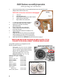
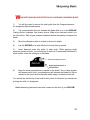
Refer to Ripsaw owners' information online at
www.ripsaw.com/owners.html for instructions and parts information
Table of Contents
Safety instructions ...................................................................….
1
Assembly
Chainsaw assembly and preparation
..............................…
Compatible chainsaws and sprockets ………………………
RIPSAW assembly ….........................................................….
2
2
3
Dimension plate assembly …........................................….
Guide beam assembly.......................................….………
4
5
End clamp assembly ……………………………………………..
6
Blades
Changing blades …..............................................………..
Tracking blades
Drive wheel …………………………… ……………..
Idler wheel ………………………
………………
Sharpening blades …....................................................…
11
12
12
13
Carbide guide adjustment/replacement ……………………………… 11
Log capacity ……………...............................................…………
14
Sawing wood ………….......................................................…….
15
Parts diagrams
Front covers
………..........................................……
Ripsaw ………………...............…............................………
End clamps …………………………………………………..
7
10
6
Parts list …….........................................................………………
8-9
Warranty / Guarantee
16
.............................................………….
Safety instructions
Proper operation of The RIPSAW is essential to avoid serious personal injury to
the operator and bystanders. Keep hands, feet, face, and clothing away from all
moving parts of the saw at ALL TIMES.
Read through the entire manual thoroughly. If you are uncertain of any
procedures in this manual, please consult S.I.R. for assistance. (256) 728-3070.
1.
Always wear eye and ear protection while operating the RIPSAW or
chainsaw.
2.
If you plan to rest the log on trestles, be sure that they are steady and at a
comfortable height for you to work with.
3.
Before starting the saw, make sure that the log is secure and that it will
not move while you are pushing the saw through it.
4.
The use of the RIPSAW is a one-person operation. If you should require
assistance in moving logs or cut lumber, ensure that the person is wearing
protective equipment and keep at a safe distance from the sawmill while it is in
operation.
5.
For re-fueling gasoline powered sawmills, extinguish all smoking
materials, stop the engine and allow it to cool. prepare the gas/oil mixture as
instructed in your chainsaw owner’s manual.
6.
Keep the blade guard closed until just before starting a cut.
7.
Keep all spectators at least 20 feet away from the milling operation.
1
Stihl Chainsaw assembly/preparation
(When providing your own chainsaw)
1.
Clean the mounting surface on the powerhead and remove the following parts.
(Retain these parts for future use.)
NOTE: Be sure that the chain brake is disengaged.
a.
b.
c.
d.
e.
2.
3.
4.
5.
6.
7.
8.
2 bar nuts
chain/sprocket cover
bumper spike, bolts and nuts which fasten it
snap ring from crank shaft
large washer from crank shaft
A 7 tooth spur gear sprocket is required to
run the sawmill with some Stihl models.
Replace the sprocket if necessary.
(See chart below)
Place small washer onto crankshaft.
Secure washer with the snap ring you
previously removed.
Apply liquid gasket material to shaded area in
diagram below.
Adjust bar oiler flow to a minimum, by inserting a
small screwdriver into slot located on the bottom
of the powerhead and turning it counterclockwise.
Attach powerhead to the RIPSAW using the instructions on page 3.
MAKE SURE BAR OILER CONTAINS AN AMPLE SUPPLY OF OIL.
FAILURE TO DO SO WILL RESULT IN RIPSAW GEAR FAILURE.
Compatible chainsaws for adaptation to the
Ripsaw portable sawmill
Apply liquid gasket here
Stihl models: 028, 029, 034, 036, 036PRO,
038, 039, 044, 046, 064, and 066, MS290,
MS360, MS380, MS390, MS440, MS460,
MS660, E20 and MSE220 electrics
Jonsereds models: 2065, 2165, 2071
Husquvarna models: 365 , 371, 395
Stihl sprocket part numbers
Stihl 026
Stihl 026 w/adj. oiler
Stihl 028, MS280
Stihl 029, MS290
Stihl 034
Stihl 036, MS360
Stihl 038, MS380
Stihl 039, MS390
Stihl 044/046,
MS440, 460
Stihl 064/066, MS660
2
1121 640 2003
1121 640 2004
1118 640 2003
1125 640 2004
1125 640 2004
1125 640 2004
1119 640 2000
1125 640 2004
1128 640 2000
1122 640 2002
7 tooth spur sprocket
Assembly instructions
RIPSAW accessories are located inside guide beams
1.
2.
3.
4.
5.
6.
7.
8.
9.
10.
Release blade tension by loosening tension bolt.
Loosen and remove cover knobs from front cover plates.
Remove Drive cover plate from sawmill. (plate with RIPSAW decal)
Remove bar nuts from chainsaw.
Position chainsaw studs through adapter block on RIPSAW.
Rotate sprocket to engage drive mechanism.
Re-install bar nuts into recesses in adapter and tighten them securely.
Re-install Drive cover plate. (Be sure that locating pins are through the
holes in cover plates before installing and tightening cover knobs.)
Re-install cover knobs and tighten securely.
Tighten the tension bolt until the indicator reaches the white line.
Refer to chainsaw owner’s manual for the proper oil/gasoline ratio.
Maintain an ample supply of bar and chain oil in the reservoir to
lubricate the drive mechanism of the RIPSAW.
3
Dimension plate assembly
RS000 18 (NOT SHOWN)
PLASTIC PLATE
RS901 18
T NUT/STUD (2)
RS000 16
DIMENSION TUBE
RS999 23
DIMENSION NUT - IDLER
RS000 17
DIMENSION PLATE
. . .
.
RS000 19
GUIDE ARM
RS000 15
HANDLE BRACKET
RS999 22
DIMENSION NUT - DRIVE
RS000 20
GUIDE FINGER
RS800 19
GUIDE FINGER KNOB (1/4-28)
Figure 1. Dimension plate assembly
1.
2.
3.
4.
5.
6.
7.
8.
9.
4
Remove dimension plate and parts from box.
Slide guide arm under handle bracket with square pin facing downward.
RS800 02
Install and tighten handle to secure guide
arm.
DIMENSION
PLATE HANDLE
Remove T nut studs from dimension plate.
Slide T nut studs through slots in rear drive and idler plates, with the
threaded stud pointing towards you.
Attach dimension plate by putting studs through holes in dimension tube.
Install Dimension plate nuts.
Slide guide finger onto guide arm (Figure 1) and tighten knob.
Adjust guide arm and finger to accommodate the size of each log you cut.
Guide beam assembly
TOP
TOP
RS000 46
SUPPORT PIN
BUSHING
( 4 ) 500 31
RS000 47 -2” SUPPORT PIN
RS000 48 - 3” SUPPORT PIN
000 49
RS500 31
3/8-24X1-1/2 SET SCREW (4)
SIDE VIEW
RS000 49
SUPPORT PIN KNOB
2005153
RS100
COUPLING CLAMP
Figure 2. Guide beam assembly
1.
2.
3.
4.
5.
6.
7.
Remove coupling clamp and other accessories from guide beam.
Install coupling clamp half way into guide beam with bushing.(Align set
screws with holes.)
Lightly tighten the last setscrew to keep clamp from moving.
Place the end of the main guide beam onto clamp lining holes up with setscrews.
Secure guide beams by tightening all four setscrews.
Install proper support pin into bushing after placing beam on top of log.
(The pin should not be above the top surface of the guide beam.)
Insert support pin knob and tighten it.
Please note:
Both the Guide Beams and End Clamps are made to be affixed on either the left or right
side. It is imperative that you set up the machine with all of the knobs on the same side
of the unit to avoid interference during the cutting process.
5
End clamp assembly
RS800 15
RS100 55
RS000 57
END CLAMP
CLAMP EXTENDER
END CLAMP BAR
6
Front Drive Cover
ROLL PIN
WASHER
BLADE GUARD
SPRING
BLADE GUARD
HANDLE
TRACKING BLOCK
BLADE GUARD MOUNT
BLADE GUARD ASSEMBLY
Front Idler Cover
RS000 03
FRONT TENSION ARM
RS800 17
COVER KNOB
7
RIPSAW PARTS LIST
8
RS000 01
RS000 02
RS000 03
RS000 04
RS000 05
RS000 06
RS000 07
RS000 08
RS000 09
RS000 10
RS000 11
RS000 12
RS000 13
RS000 14
RS000 15
RS000 16
RS000 17
RS000 18
RS000 19
RS000 20
RS000 22
RS000 26
RS000 27
RS000 28
RS000 29
RS000 30
RS000 31
RS000 36
RS000 38
RS000 40
RS000 42
RS000 46
RS000 47
RS000 48
RS000 49
RS000 51
RS000 57
RS000 59
RS000 60
RS000 68
RS000 81
RS001 01
RS001 02
RS100 28
RS100 37
RS100 51
RS100 52
TOP TUBE
MAIN TUBE
TENSION ARM-FRONT
TENSION ARM.-REAR
FRONT DRIVE COVER
REAR DRIVE PLATE
FRONT IDLER COVER
REAR IDLER PLATE
REAR DRIVE COVER
REAR IDLER COVER
LOCATING PIN
HEX PIN
PIVOT PIN
AXLE
HANDLE BRACKET
DIM. PLATE TUBE
DIMENSION PLATE
DIM. PLATE PLASTIC
GUIDE ARM
GUIDE FINGER
BLADE GUIDE BLOCK
GUARD WIRE - DRIVE
GUARD WIRE - IDLER
GUARD WIRE MOUNT
TENSION ASSEMBLY
TENSION BOLT
TENSION INDICATOR
WHEEL SCRAPER - DRIVE
BLADE GUARD PIVOT
BLADE GUARD HANDLE
END CLAMP
SUPPORT PIN BUSHING
SUPPORT PIN - 2"
SUPPORT PIN - 3"
SUPPORT PIN KNOB/STUD
TRACKING BLOCK
END CLAMP PIN
GUIDE BEAM W/BUSHING
MAIN GUIDE BEAM
UPPER BLADE GUARD
CLAMP EXTENDER
DRIVE WHEEL
IDLER WHEEL
AXLE BUSHING
BLADE GUARD ASSEMBLY
COUPLING CLAMP
COUPLING CLAMP SPACER
RS100 53
RS100 54
RS100 55
RS100 56
RS100 63
RS500 11
RS500 12
RS500 14
RS500 15
RS500 16
RS500 17
RS500 18
RS500 19
RS500 20
RS500 21
RS500 22
RS500 23
RS500 24
RS500 25
RS500 26
RS500 27
RS500 28
RS500 29
RS500 31
RS500 32
RS500 33
RS500 34
RS500 35
RS500 36
RS500 37
RS500 38
RS500 39
RS500 40
RS500 42
RS500 43
RS500 44
RS500 45
RS500 46
RS500 47
RS500 70
RS500 71
RS500 72
RS700 01
RS700 02
RS700 03
RS700 04
RS700 05
COUPLING CLAMP BASE
COUPLING CLAMP NUT BAR
END CLAMP BAR W/BUSHINGS
WHEEL SCRAPER - IDLER
END CLAMP KNOB
5/16 -18X1-3/4 COUPLING NUT
/16 -18X3 SOC CAP BOLT
1/4X3/4 ROLL PIN
10-32/3/8 FLAT HD SCREW
10-32/3/8 BUT SOC CAP SCREW
1/4-28X1 SET SCREW W PATCH
1/4-20X3/4 FLAT HD SCREW
5/32X3/8 ROLL PIN
1/4-20X1/2 HEX BOLT
1/4-20X1-1/4 HEX BOLT
1/4-20 HEX NUT
10-32X1/4 PAN HD SCREW
10-32X5/8 PHIL PAN HD SCREW
10-32X5/16 PAN HD SCREW
1/4-28X3/4 HEX BOLT
10-32 KEP NUT
1/4-20X5/8 HEX BOLT
1/4 ID FLAT WASHER
3/8-24X1-1/2 SET SCREW
10-32X3/8 PHIL PAN HD SCREW
1/4-20X1 SET SCREW
3/8-16X2 SET SCREW
1/4-20X1-1/4 SET SCREW
1/4-28X1 SET SCREW
3/16X3/8 RIVET
BLADE GUARD PIVOT
1/4-20X7/8 SET SCREW
FENDER WASHER 5/16 ID
5/16-18X1-1/4 SLOT FLT HD SCREW
5/16-18 STOP NUT
10-32X1-3/4 PAN HD BOLT
10-32X1-1/2 PAN HD BOLT
10-32 HEX NUT
5/16 NUT
BEARING - WHEEL/PINION
BEARING - BLADE GUIDE
CARBIDE INSERT
TRIM HATCHET
LOG CLEANING BRUSH
FRAMING SQUARE
SAFETY GOGGLES
BLADE SHARPENER
RS700 06
RS700 80
RS700 83
RS700 84
RS800 11
RS800 15
RS800 17
RS800 19
RS800 28
RS800 37
RS800 46
RS901 18
RS999 22
DIAMOND SHARPENING STONE
BLADE
BLADE GUARD SPRING
ANTI-VIBRATION PAD
DIMENSION PLATE KNOB
EXTENDER KNOB
COVER KNOB
KNOB - GUIDE FINGER
3/16 ALLEN WRENCH
1/8 ALLEN WRENCH
VIDEO
T NUT / STUD
DIMENSION PLATE NUT – DRIVE
RS999 10
IDLER TRACKING BRACKET
RS999 11
IDLER TRACKING NUT
RS999 12
¼ -20 X 2 STUD
RS999 13
TRACKING WASHER
RS999 14
¼ - 20 NUT
RS999 15
RSH00 11
RSH00 12
RSH00 13
RSH00 15
RSH00 70
RSH50 44
RSH50 55
RSH70 38
RSH70 39
RSH70 47
RSH70 48
RSH70 49
RSH70 50
RSH70 51
RSH70 52
RSH70 53
RSH70 54
RSH90 55
ST800 99
¼ -20 ALLEN BOLT (TRACKING)
DRIVE COUPLING
DRIVE DISK - ELECTRIC
ADAPTER BLOCK
PINION COVER
PINION SPACER
RING GEAR
PINION GEAR
038 SPROCKET
064 SPROCKET
036 SPROCKET
044 SPROCKET
20" BAR - STIHL
CHAIN FOR 20" BAR
STIHL WASHER
2.6 STIHL ENGINE OIL
STIHL BAR NUT
STIHL SNAP RING
PINION ASSEMBLY
STIHL-20" BAR & CHAIN
9
REAR VIEW
RS000 31
FRONT VIEW
RS 000 02
RSH59 44
RS001 01
RS000 09
RS000 14
FRONT
RS000 36
RS999 10
(SEE DIAGRAM BELOW)
RSH00 13
RS000 11 (6)
RS 000 68
RS500 71
RS100 56
RS000 08
RS000 06
RS 000 01
RS500 72
SIDE VIEW
RS000 22
RS100 22 –
BLADE GUIDE BLOCK ASSEMBLY
RIPSAW DIAGRAM
RS000 04
RS000 27
RS001 02
RS000 28
RS500 70
RS000 10
TOP VIEW
RS H00 70
RS 500 70
SIDE VIEW
RS H00 11
RS999 11
RS999 13
RS999 12
RS999 14
RS H50 55
RS000 30
TOP VIEW
RS000 12
RS H90 55 – PINION ASSEMBLY
TENSION
RS000 29
REAR IDLER PLATE
RS999 15
FRONT VIEW
RS000 52 IDLER TRACKING ASSEMBLY
Changing blades
Wear gloves and eye protection while handling blades.
1.
2.
3.
4.
5.
Release blade tension. (Turn tension bolt counter-clockwise.)
Remove cover knobs.
Remove front tension arm, Drive cover and Idler cover.
Slide blade toward front of saw and out of guide blocks.
Slip blade over the edges of the bottom of the Drive and Idler wheels by tipping it up
and outward.
6. Rotate blade up and out of safety guard.
7. To replace blade perform above procedures in reverse. Make sure that locating pins
are through the holes in the front covers before installing and tightening cover knobs.
8. Tighten the tension bolt until the tension indicator reaches the white line on the rear
tension arm.
Carbide guide replacement/adjustment
Carbide guides may need to be adjusted occasionally. If your sawmill is making wavy cuts
adjusting the carbide guides may solve the problem.
If using blades of thicknesses other than .025” you will need to adjust the carbide guides.
1
2
3
4
1.
2.
3.
4.
5.
Install blade if necessary
Loosen screws
Place a piece of paper between blade and top carbide
Using vise grips or pliers, squeeze the carbides tother
Tighten screws while holding carbides in place
11
Blade trackin g
Drive wheel…
The tracking set screw is located on the front drive cover at the wheel hub. Turning the
set screw will move the wheel, which in turn will move the blade forward and backward.
The smooth side of the blade should track approximately 1/32” from the rear rim of the
Drive wheel.
d)
e)
f)
g)
h)
a) Install a new blade if necessary.
b) Loosen tracking lock screw.
c) Adjust the Drive wheel tracking screw all the way in.
Tighten the blade so that the indictor reaches the white line.
Rotate the blade by hand to make sure that it will not come off the wheel when the
saw is jogged (Jogging the saw consists of starting the motor and running the saw
intermittantly).
Jog the saw while turning the tracking screw counterclockwise, until the blade leaves
the back flange of the Drive wheel.
Continue jogging the saw while adjusting the Idler wheel tracking bolt.
Lock the Idler tracking bolt by tightening the 1/4-20 nut.
Idler wheel…
The tracking adjustment for the idler wheel is located on
the rear side of the sawmill.
1. Loosen locking nut, using a 7/16” open-end wrench.
2. Make tracking adjustment using a ¾” wrench by
turning tracking nut clockwise to move blade backwards
(towards you) and turning nut counter-clockwise to move
blade forward. (Away from you) You will need to follow
the tracking nut with the lock nut to achieve the proper
results.
3. Tighten locking nut.
The smooth side of the blade should track evenly with
the rear edge of the Idler wheel.
1/32
REAR
FLANGE
BLADE
(teeth)
BLADE
REAR TENSION ARM
TENSION INDICATOR
IDLER TRACKING BRACKET
LOCKING NUT
(located between Rear Idler
Plate and Tracking Bracket)
IDLER WHEEL
(teeth)
DRIVE
WHEEL
RIMLESS EDGE
12
Sharpening blades
W
EAR SAFETY GOGGLES, FACE PROTECTION AND GLOVES WHILE SHARPENING BLADES
1)
You will first need to remove the steel guide from the Oregon sharpener
for sharpening Ripsaw saw blades.
2)
It is recommended that you sharpen the blade while it is on the RIPSAW.
Unplug electric chainsaw from power source. Make sure chainsaw switch is in
the off position. Shut off gas powered chainsaw before attempting to sharpen the
blade.
3)
Move the dimension plate to at least a three-inch depth.
4)
Lay the RIPSAW on its side with the front side facing upward.
5)
Insert diamond stone into gullet of each tooth. While applying slight
pressure upward so thtat , move the stone in and out (Forward and backward) in
short strokes under the cutting tip of the blade.
Diamond sharpening stone
Apply slight pressure in
this direction
6)
Keep the stone perpendicular or square to the blade. Two or three strokes
will sharpen each tooth. (oversharpening will shorten the blade life.) Move
upward on the stone as the diamond wears away to maximize stone life.
You should see that the tip of the tooth is shiny when it is dull and you should see
a sharp line after it is sharpened.
Blade sharpening instructions are also located on the front of your RIPSAW
13
Log Capacity
Larger than 20” diameter logs can be cut by using the following procedure.
1. Make one flat trim cut as deep
as possible.
2. Make a second trim cut at
approximately a 30° angle to the
first cut.
3. Make a third cut at a 30° angle
to the second cut.
4. Cut a board off the flat from the
second cut.
5. Alternate cutting surfaces until
the log is small enough to be cut
straight through.
The resulting boards will have to be trimmed to obtain square edges. The board
thickness will be limited until the log is trimmed to at least the rated maximum capacity.
Special cuts
Clapboards
Starting with an oversized plank, clapboards can be cut by setting the
dimension plate at an angle.
Curved boards
A curved board can be cut by placing a 2”x 6” board over a curved log.
Cutting with the 2”x 6” as a guide will yield a curved top which can be
duplicated.
14
Sawing wood
1. Plan the use of your log to allow for maximum use.
2. Place the log securely on a stand or position it securely on the ground with the side you want to
cut, facing upward. Having the log in an incline position will make it easier to push the mill through
the log.
3. Trim off any high spots on the log using another chainsaw or the trim hatchet.
4. Position the guide beam on top of the log and secure it with the end clamps ( Keep all knobs on the
same side of the log to avoid interference during the cutting process.. Adjust the height of the end
clamps to accommodate any protrusions on the log. (Clamp extenders may be required. See Figure 3.)
5. Turn the end clamp pins so that the edges are radial to the center of the log.
6. Drive the end clamp pins into the end of the log using the hammer end of the hatchet.
7. Tighten extender and end clamp knobs.
8. Install support pin and support pin knob.
9. In setting the depth of first cut, make sure that the blade will clear the end clamps and extenders.
10. Open blade guard.
11. Gasoline powered sawmills should be started and warmed up on the ground. Electric units should
be plugged into the proper size extension cord and electrical supply.
12. Place sawmill on top of guide beam and adjust guide finger to enable it to ride along the side of
the guide beam.
Never move the RIPSAW backwards while the blade is in motion
13. Position the RIPSAW at a 45° angle to the end of the log to start the cut.
14. Start cut in to log slowly.
15. Rotate sawmill to 90° after guide finger comes in contact with guide beam or log.
16. Feed the sawmill into the wood, (Do not force) Allow the saw to maintain a good
blade speed.(This will give the best cut and will prevent overloading.)
17. Cut through the end of the log.
18. Close the blade guard and remove sawmill from the guide beam.
19. Remove the support pin from guide beam.
20. Loosen end clamp knobs and remove guide beam.
21. Wiggle end clamps to free the end clamp pins from the end of the log.
22. Remove the waste slab.
23. Rotate the log 90° (see figure 4-framing square)
24. Repeat the previous procedures.
This will give you your second trim cut. To yield boards with finished edges you will need to trim
cut another side by dropping the dimension plate down to the maximum depth you can obtain and
either guide the saw off the surface of the side you just cut or place a guide beam on top of it first.
Once you have three trim sides you are now ready to cut boards with finished edges.
FRAMING SQUARE
GUIDE BEAM
FIRST CUT
LOG
15
Warranty
6 Month warranty on RIPSAW parts
Every RIPSAW is thoroughly inspected and tested before leaving the factory. Should any
trouble develop with the saw or its components, please contact our office AT 256-7283070 for further instructions. Returns will not be accepted without prior authorization.
Upon the completion of any warranty work, the items repaired will be shipped back to
you, freight pre-paid.
The RIPSAW warranty does not apply under these conditions:
1.
2.
3.
4.
5.
6.
Repairs are necessary due to normal wear.
Repairs have been attempted or made by someone other than S.I.R.
personnel.
The unit has been in an accident.
Misuse is evident. (Such as: overloading or operating beyond rated
capacity)
The unit has been operated after partial failure.
The unit has been used with an improper accessory.
Guarantee
Southeastern industrial Resources stands behind each of its RIPSAW portable sawmills
with a 30-day, money-back guarantee. Authorization must be obtained prior to the return
of any S.I.R. product. Refunds will be less shipping and a 20 % restocking charge.
16