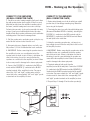
1
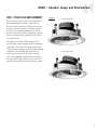
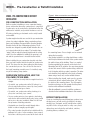
Advantage
TWIST & TILT
OWNER’S MANUAL
Contents
Introduction – The Russound Advantage . . . . . . . . . . . . . . . . . . . . . .3
Space and Wall Requirements . . . . . . . . . . . . . . . . . . . . . . . . . . . . . . .4
Impedance Matching for Amplifier and Speakers . . . . . . . . . . . . . .4
Speaker Care . . . . . . . . . . . . . . . . . . . . . . . . . . . . . . . . . . . . . . . . . . . . .5
Getting Started . . . . . . . . . . . . . . . . . . . . . . . . . . . . . . . . . . . . . . . . . . .6
WHO – Installer Skills and Tools Required . . . . . . . . . . . . . . . . . . . . .6
WHAT - Speaker Usage and Environment . . . . . . . . . . . . . . . . . . . . . .7
WHEN - Pre-Construction or Retrofit Installation . . . . . . . . . . . . . .8
WHERE - Speaker Placement . . . . . . . . . . . . . . . . . . . . . . . . . . . . . . . .9
WIRE - Wire Requirements . . . . . . . . . . . . . . . . . . . . . . . . . . . . . . . . .12
HOW - Painting the Speaker Frames and Grilles . . . . . . . . . . . . . . .13
HOW - Cutting Wall/Ceiling Opening for Speakers . . . . . . . . . . . . .14
HOW – Hooking Up the Speakers . . . . . . . . . . . . . . . . . . . . . . . . . . .16
HOW – Final Assembly of Speakers . . . . . . . . . . . . . . . . . . . . . . . . . .18
HOW - Testing Speaker Polarity and Channel Connections . . . . . .19
Specifications . . . . . . . . . . . . . . . . . . . . . . . . . . . . . . . . . . . . . . . . . . . .20
Warranty . . . . . . . . . . . . . . . . . . . . . . . . . . . . . . . . . . . . . . . . . . . . . . . .23
2
Introduction
THE RUSSOUND ADVANTAGE
Thank you for selecting Russound Advantage Series
speakers. Like all Russound speakers, they combine
acoustic technology with durability to provide years of
listening enjoyment. The Advantage speaker line is composed of the Music and Hi-Fi Series.
The Music Series is designed to provide an optimum
balance between performance and price, delivering
superior sound for all applications at a most affordable
cost. The Music Series is perfect for multi-room audio
systems as well as surround sound applications, providing exemplary reproduction throughout the home.
The Hi-Fi Series combines the finest components with
our most advanced drivers to deliver exceptional performance in every application. From background music
to spectacular surround sound, Hi-Fi Series speakers
offer the finest sound around.
Twist & Tilt™ technology allows Advantage ceiling speakers to deliver the best direct listening performance by
modifying their dispersion angle 15 degrees, to focus
sound on the prime listening area. For general background sound delivery, Twist & Tilt speakers can be set
for uniform dispersion, filling the room with excellent
sound. This ability to focus the sound where you want it
most provides increased location flexibility with heightened fidelity. Better attention to aesthetic location is now
possible, without compromising performance.
In addition to Twist & Tilt focused dispersion and toolfree mounting features, Russound Advantage speakers
feature high quality drivers, sophisticated crossover networks, and advanced designs to ensure optimum reproduction in your home, no matter what the source material may be.
WOVEN GLASS FIBER WOOFER/MIDRANGE
CONE
Our woven glass fiber cone employs the best of modern
technology to deliver an optimum balance of performance. Its superior transient response and light weight
produce excellent low distortion voice reproduction and
high efficiency. The result is exceptional sound from
deep bass through the all-critical midrange frequencies.
LARGE HIGH-ENERGY MAGNETIC MOTOR
SYSTEMS
These powerful motors drive the woofer/midrange cone
to reproduce sound. Their advanced Finite Element
Analysis design means they are optimized to mate perfectly with the glass fiber cones, delivering all the power
needed with finesse and superior control. A dual vented
design and large Kapton® voice coil ensure adequate
power handling under the most demanding situations.
SILK OR ALUMINUM DOME TWEETERS
These fluid cooled devices utilize rare-earth Neodymium
magnet assemblies and lightweight domes to reproduce
every subtle nuance of the musical or cinema sound
source. A computer-designed lens helps smooth their
response and aids in delivering wide dispersion for
excellent sound throughout the listening area.
COMPUTER DESIGNED ASYMMETRICAL
CROSSOVERS
The crossover is the traffic cop for the audio signal,
dividing the lows from the highs and sending them off to
the proper driver element. It also matches driver efficiencies and phase relationships to make sure that the
different drivers work in unison. Advantage asymmetrical crossovers are very sophisticated designs, blending
and matching the output of our proprietary drivers into a
seamless and accurate sound field. Asymmetrical refers
to the roll-off slope of the woofer/midrange being different from the roll-on slope of the tweeter. The result is
both better driver integration and better time coherence
in the speaker’s output. We also use high quality components to ensure long life and excellent unit-to-unit consistency.
HIGH FREQUENCY SWITCH
This adjustment allows you to tailor the sound of
Advantage speakers to better match the listening environment. The switch offers a flat response position (-)
and a plus 3 dB position (+). It is located on the
crossover network of Twist & Tilt models.
3
Space Requirements & Impedance Matching
SPACE AND WALL REQUIREMENTS
SPACE REQUIREMENTS
Russound Advantage Twist & Tilt speakers require at
least 1.4 cubic feet of space behind the speaker for optimal performance.
WALL REQUIREMENTS
ACCEPTABLE INSTALLATION SITUATIONS:
* Wallboard/plaster ceilings - The dense, rigid nature of
wallboard (or lath and plaster) acts as a superb
speaker baffle.
* Suspended ceiling – only if the ceiling tile is reinforced with wood or particle board
UNACCEPTABLE INSTALLATION SITUATIONS:
* Brick or concrete ceiling where the wallboard or paneling is attached to thin furring strips – This type of
ceiling can’t provide proper depth (clearance) for the
back of the Russound Advantage speakers.
* Locations concealing pipes, heating ducts and AC
wiring - These elements can complicate speaker
mounting and installation of speaker wire. AC wiring
can induce hum caused by close proximity to the
speaker.
IMPEDANCE MATCHING FOR AMPLIFIER AND
SPEAKERS
Not all amplifiers or receivers can safely operate two
sets of speakers at once. If you intend to run your
Russound Advantage speakers and your main speakers
concurrently, or if you intend to hook up and run two
sets of speakers at the same time, it’s important to consider both the impedance of the speakers and the capabilities of the amplifier or receiver you’re using.
A speaker’s impedance rating indicates the amount of
electrical resistance it places against current flowing
from a receiver’s outputs. If the total speaker load
does not present adequate resistance, the receiver
increases its power output. Low-impedance speakers
may hamper operations of receivers not designed to
deliver large amounts of current to low-impedance
4
loads. This may lead to greater distortion, and causes
the receiver to run hot or activate its protection circuitry.
First, consult the owner’s manual for your amplifier or
receiver. It should state the minimum speaker impedance during multiple speaker operation. The impedance
may also be printed on the back of the amplifier/receiver next to the speaker connectors. If you can’t readily
determine this information, consult the dealer where you
purchased the amplifier or receiver, or call the manufacturer of the product in question.
The impedance rating for your Russound Advantage
Music Series speakers is 8 ohms, and 6 ohms for the
Hi-Fi Series. Next, determine the impedance of your
other speakers. It may be printed on the back of the
speaker near the connection terminals, or you can consult the speaker’s owner’s manual. Speaker impedance
must be equal to or higher than the amplifier/receiver
speaker output impedance rating. For instance, an
amplifier/receiver that is rated for two pair of 8 ohm
speakers cannot support two pair of 4 ohm speakers.
If the amplifier/receiver is not rated for the speaker configuration desired, external volume controls and/or
speaker selectors can maintain the impedance levels
that will allow your amplifier/receiver to operate safely.
Russound makes a complete line of these products,
from Impedance-Matching Volume Controls to
Impedance-Matching Speaker Selectors. Ask your
Russound dealer for details or request a catalog from
Russound at 800-638-8055 (U.S. and Canada) or
+1-603-659-5170 from outside the U.S.
Speaker Care
SPEAKER CARE
Russound Advantage Series speakers are built with
quality materials to last a lifetime. They should work for
as long as you own your home and longer if you avoid
the following:
• Too little power at high volumes
• Too much power
• Transients (immediate loud passages, thumps, etc.)
TOO LITTLE POWER AT HIGH VOLUMES
Speakers can be damaged when they are driven by an
amplifier/receiver that isn’t capable of delivering all the
“clean power” that is being demanded. When an amplifier/receiver runs out of current due to high demand
while trying to re-create musical peaks, it causes a type
of output signal distortion called clipping. Clipping not
only makes the music sound unclear, over time it can
damage or destroy the speakers. If you’re listening at
loud volumes you may be unaware that clipping is
occurring, but the damage may already be done, as clipping damage can be instantaneous or cumulative. If you
like your music loud, consider using an amplifier/receiver with at least 50 watts per channel but remember:
you can damage any speaker with clipping, no matter
how well it is built.
TRANSIENTS
Transients are sudden uncontrolled signal changes that
can seriously damage any speaker, including your
Russound Advantage speakers. Transients may be
caused by turning the system on or off while the volume
is at a maximum level, or by disconnecting any hook-up
cables while the system is on, creating a burst of low
frequency hum. These conditions can cause serious
speaker damage and should be avoided. As a general
rule, always unplug the amplifier from the AC mains
before connecting or disconnecting any signal or speaker cable.
Note: Russound does not guarantee its speakers against abuse,
including too little power at high volumes and too much
power. Damage from clipping or too much power is revealed
simply by looking at the speaker’s voice coils. When used with
care and common sense, your Russound speakers should provide a lifetime of listening pleasure.
TOO MUCH POWER
There’s nothing wrong with driving your Russound
Advantage speakers with as much power as they are
rated for. The extra power helps them provide full, rich
sound and excellent transient response. However, you
should not be heavy-handed with the volume control. If
the music begins to sound distorted in any way, back off
the volume.
5
Getting Started & WHO – Installer Skills and Tools
There are several related factors that must be considered before the installation of your Russound Advantage speakers:
WHO:
Who is doing the installation, the homeowner, or a professional installer?
WHAT:
What is the installation environment and the intended use (serious listening or background)?
WHEN:
When will the installation be performed – during pre-construction or retrofit in an existing
home?
WHERE:
Where is the best speaker location and where are the available speaker locations?
WIRE:
Wire should be what gauge and what length? Can the speaker wires be run to the intended
location? Will there be any IR receivers mounted in any Iso-Mount speaker locations? If so,
what are the wiring requirements?
HOW:
How are the speakers installed?
WHO – INSTALLER SKILLS AND TOOLS REQUIRED
This manual is designed to make your Advantage Series
speakers as easy to install as they are to listen to. If
you’ve had any home “do-it-yourself” experience, you
should find installation of your new speakers a manageable job. You should have a basic understanding of
hand and power tool operations, a working knowledge of
your audio system, and be able to operate a multimeter.
TOOLS NEEDED FOR INSTALLATION IN
EXISTING WALLS:
•Drill with a 1-inch flat bit
•Drill bit 1/4” larger than the diameter of the speaker
wire
•Retractable utility knife, Roto Zip®, Dremel®, or keyhole saw
• #2 Phillips-head screw driver to fit the screws for the
integral swing-out mounting clamps
• #1 Phillips-head screw driver to fit earthquake screw
• Bubble level
• Pair of diagonal cutters or wire strippers
• Stud finder
• Multimeter
• Cardboard mounting template (included with speakers)
6
• Pencil
• Length of stiff wire about 3 feet long (a straightened
wire coat hanger works well)
• Insulated staples for securing speaker wire
• 1.5V AA battery
• Masking tape
• Paint and applicator for painting the grille and outer
frame
• Fiberglass screening (one square foot for each Twist
& Tilt speaker only)We suggest you read through this
manual first before proceeding with installation to
familiarize yourself with the entire installation
process. If you then decide that installing your
Russound Advantage Series Speakers is beyond your
skills, call your Russound dealer to arrange for professional installation. Be ready to tell your installer if
the speakers will be used for direct listening or for
background sound, and to discuss the desired speaker locations.
Note: For shipping, grilles are placed in protective cardboard sleeves packed between the two loudspeaker
assemblies. Use caution when unpacking as the cardboard sleeves are also the cutout templates.
WHAT – Speaker Usage and Environment
WHAT - SPEAKER USAGE AND ENVIRONMENT
Figure 1
(0° angle) Uniform dispersion
Before you decide where you want to install your
Russound Advantage speakers, you’ll need to
determine their intended use. Will you be sitting in
one place listening to music or watching a movie,
or will you be playing background music during
domestic and social activities? Advantage speakers
have been designed to be suitable for most listening environments.
Advantage Series Twist & Tilt speakers can be
used for both serious listening and for background
applications. The Twist & Tilt design allows these
ceiling speakers to deliver the best serious listening
performance by modifying their dispersion 15
degrees to focus sound on the prime listening
area. For background or surround sound delivery,
the same Twist & Tilt speakers can be set for uniform dispersion to fill a room with excellent sound.
(15° angle) Focused dispersion
7
WHEN – Pre-Construction or Retrofit Installation
WHEN - PRE-CONSTRUCTION OR RETROFIT
INSTALLATION
Figure 2 New construction use of Rough-in
Bracket
Not for use with Retrofit applications
PRE-CONSTRUCTION INSTALLATION
Built-in speaker installation is more convenient during
home construction than after construction is completed.
Speaker wire can be routed to the destination before the
wallboard is installed, and possible hindrances such as
AC wiring, plumbing, or ductwork can be easily located
and avoided.
Speaker rough-in brackets are used in the pre-construction
phase of speaker installation during construction of new
homes and additions. Russound offers Speaker Rough-In
Brackets for the full line of Advantage speakers. These
brackets are designed to provide drywall installers the correct cut-out pattern for the speakers. The brackets have
“wings” that are nailed/screwed/stapled onto the ceiling
studs. Once the wallboard is installed, the opening is cut
out and the speaker frame is inserted into the bracket.
When installing the pre-construction bracket, note that
there are holes molded into the bracket for speaker wire
tie-off. This keeps the wire from getting lost later during
the construction process. You can also tie the wire to
the bezel/mounting assembly once it’s installed, using
any of the rotating clamp towers.
DURING NEW INSTALLATION, KEEP THE
FOLLOWING TIPS IN MIND:
• Use a small level to verify that the rough-in bracket is
straight.
• If possible, run speaker wires after AC wiring is in
place to avoid induced hum caused by close parallel
proximity of the two types of wire.
• If possible, run speaker wires after plumbing is in
place; wire can bend, pipes cannot.
• Secure speaker wires in place against a stud along
vertical runs with insulated staples only, being careful
not to pierce the wire insulation. Allow a bit of slack
for expansion of building materials.
• Horizontal runs should be routed through holes
drilled in studs at roughly equal heights.
• The actual speakers should not be installed until the
wallboard is in place. In the meantime, leave several
feet of wire coiled up and secured to the back side of
8
the mounting frame. Excess length can be removed
during final assembly.
• Any speaker installed in a ceiling should have a safety
wire firmly tied between the back of the speaker assembly and the frame of the building. There is a marked
location provided for this purpose on the back of all
Advantage Twist & Tilt speakers. Use any strong insulated wire and connect it to the speaker being careful not
to let it interfere with the speaker’s operation. The other
end should be firmly attached to the studs or flooring
above using a hook, nail, or other reliable fastener.
• When installing the drywall, make sure the speaker
cut-out hole doesn’t extend farther than 1/4” from
the inside of the mounting frame. The flat rough-in
brackets and wings are thin enough that they won’t
interfere with wallboard installation.
• After the wallboard is secured, install the speakers as
described in the installation instructions in this manual.
RETROFIT INSTALLATION
If you are installing Russound Advantage speakers in an
existing home, you will need to be diligent in locating
existing pipes, ductwork, and AC wiring before cutting
any holes in the ceiling or walls. In many cases, these
obstructions are indicated by wall outlets, switches,
plumbing fixtures, radiators, etc.
WHERE – Speaker Placement
WHERE - SPEAKER PLACEMENT
Placement can make all the difference in how your
Russound speaker system sounds. There are at least four
related considerations that factor into the speaker layout:
• The intended use: critical listening, home theater, or
background music
• The room’s physical characteristics: hard, reflective
surfaces or soft, absorbent textures
• The listening locations: a desired prime listening
spot or a need for sound throughout the room
• The available locations: unobstructed wall and ceiling
surfaces
It may happen that the ideal or desired locations for the
speakers may have to be modified for feasibility.
STEREO IMAGING
If your Russound In-wall Speakers are going to be your
primary listening source in a room, you need to consider some other factors to insure proper imaging. The
term “stereo imaging” refers to a speaker system’s ability to project music so that it sounds like the performers
are in a three-dimensional space between the speakers.
It’s the whole point of having stereo instead of monophonic sound.
To achieve good stereo imaging, the speakers are best
located 6 to 8 feet apart on the short wall of a rectangular room, if the prime listening location is opposite the
short wall. Optimally, tweeters should be located at ear
level when the listener is seated. Ceiling mounted
speakers are best located slightly forward of the listening position with the tweeter aimed toward the listener.
HOME THEATER
When setting up a home theater surround sound system, it’s preferable to use wall mount rather than ceiling
speakers for the front three channels. The three front
speakers should be at close to equal heights, at ear
level when the listener is seated. The center channel
speaker should be located above the TV screen aligned
with the center of the screen, and the left and right
speakers should be about 3 or 4 feet to either side of
the screen. Left and right speakers placed too close
together or too far apart dissipate the illusion of being
“in the action” on the screen. (continued on next page)
General Disclaimers – All rooms have different sound characteristics. Speaker location, listening location, reflective and absorptive surfaces all have a dramatic impact on the sound you hear. The following are only general recommendations and should not be considered the best or only solutions.
LEGEND:
- Ceiling Speaker
- Wall Speaker
Figure 3-B
Figure 3-A
Best for serious listening.
Stereo pair in-wall or inceiling. Six to 8 feet
apart, on the short wall of
a rectangular room, centered on the listening
area. In-wall speakers
should be at ear height
when seated, if possible.
Good for serious
listening. Stereo pair
in-wall or in-ceiling.
Six to 8 feet apart,
on the long wall of a
rectangular room,
centered on the listening area. In-wall
speakers should be
at ear height when
seated, if possible.
9
WHERE – Speaker Placement
For home theater, wall speakers for the front three channels create the illusion that the sound is coming from
the screen, which makes the viewing experience more
involving and believable. When you use ceiling speakers
for the front channels, the sound appears to come from
above the screen which is less believable. However,
excellent results are still possible if you follow certain
guidelines for placing the ceiling speakers.
1. Place the front speakers close to the same plane as
the front of the TV as possible.
For TV and movies, ceiling surround speakers should be
placed directly to the sides or rear of the prime listening
position, but be aimed away from the listener to reflect
the output off the rear or side walls. This configuration
is also suitable for a TV/movie and music mixed use.
If the prime purpose of the surround system is to listen
to music, the Iso-Mount wall speakers should be placed
closer to ear level. Ceiling speakers should be aimed at
the prime listening position.
2. Tilt the tweeters so they aim at the prime listening
position.
3. Align the center channel speaker with the center of
the screen, and place the left and right speakers no further than 4 feet from either side of the screen.
SURROUND SOUND
If the prime purpose of the surround system is to watch
TV and movies, the surround speakers should be placed
to produce a diffuse sound field. Iso-Mount wall speakers should be placed to the sides or rear of the prime
listening location, located 24 inches or more above ear
level when the listener is seated. If this speaker location
is closer than 24 inches from the ceiling, mount the IsoMount speaker baffle upside down in the wall frame
with the tweeter away from the ceiling.
5
Figure 3-C
Good for background
listening. Stereo pair
behind, above or to the
sides of the main listening area. Six to 8 feet
apart, centered on the
listening area. If in-wall
speakers are at ear
height when seated they
will be more distracting
because their high frequency response will be
more prominent. The
same is true for ceiling
speakers located directly over the listening
position as opposed to
off to the side a bit.
10
4
4
Figure 3-D
Surround sound –
The multiple surround
locations can all be
made to work as long
as the speakers are
properly directed, as per
the recommendations in
these instructions.
Numbers designate
suggested locations for
pairs.
2
2
3
3
1
1
WHERE – Speaker Placement
(0° angle) Uniform dispersion
Figure 4
Uniform: full sound dispersion
The Advantage Twist & Tilt speaker
design provides the option of either
uniform or focused dispersion,
ensuring that high quality sound fills
the chosen listening area. This ability to focus the sound where you
need it most provides increased
flexibility with heightened fidelity.
After the frame is secured, the
speaker/baffle portion installs with
a simple twist. The Twist & Tilt technology offers the option of tilting the
driver/baffle assembly 15 degrees
to focus the sound towards the chosen listening area or standard
mounting for uniform dispersion.
(15° angle) Focused dispersion
Figure 5
Uniform: full sound dispersion
11
Wire – Wire Requirements
& HOW – Painting the Speaker Frames and Grilles
WIRE CONSIDERATIONS
When purchasing speaker wire, you will need to select the
proper gauge, determine the length, and choose the brand.
Wire is measured in gauges: the higher the number, the
thinner the wire. For example, 18-gauge wire is thinner
than 14-gauge wire. The length of speaker wire you’ll
need will vary with speaker placement. The gauge of
wire you need is determined by the distance between
your amplifier/receiver and the speakers. Use the following chart as a guide:
Length
Minimum Gauge
10 to 100 ft.
16
80 to 125 ft.
14
Over 100 ft.
12
We recommend using Russound AW series speaker cable
for amplifier-to-speaker connections, but any reputable brand
of 16- to 12-gauge multi-stranded wiring is acceptable.
Incorporating optional IR receivers in Iso-Mount models
will require additional wire. Consult the selected IR
receiver model’s manual for the specific wire needs.
Care must be taken to avoid obstacles when running wire. In
general, you should pay particular attention to the following:
• Avoid locations concealing pipes, heating ducts, and
AC wiring in the general vicinity.
• Avoid running speaker wires close to house electrical
wiring for any distance. If you have to run them parallel, make sure to space the speaker wires at least
two feet from the AC line. It is, however, permissible
for speaker wires to cross paths with AC line or pass
through the same hole together with house wiring if
they separate before and after.
• Make sure that the entire wire path between speakers and amplifier is clear and not obstructed by a
floor or ceiling joist, or a masonry wall which can’t be
drilled through. Confirm ahead of time that you can
drill an outlet hole easily and in an unobtrusive spot
to connect wires with the amplifier/receiver.
• Label speaker wires at each end “left” or “right” and
include room location. This simplifies speaker/receiver hook-up once the speakers are installed.
12
HOW - PAINTING THE SPEAKER FRAMES AND
GRILLES
Russound in-wall speaker frames and grilles are pre-finished with an off-white paint. You can choose to leave
them as is or paint them with latex wall paint or aerosol
spray paint to accent or blend with the wall or ceiling.
TO PAINT SPEAKERS THAT HAVE NOT BEEN
ASSEMBLED OR INSTALLED:
1 Separate and remove the speaker baffle from the
frame and set it aside.
2 Remove the scrim cloth by gently separating it from
the inside surface of the perforated grille, being careful to
keep it clean. Store it before you begin painting.
3 Paint the outer speaker frame and grille separately.
For the grille, Russound recommends a spray application using latex paint diluted 4 to 5:1 with water. If
you’re using an aerosol spray paint, make sure that you
achieve the same coverage on both grille and frame.
4 While the paint is still wet on the grille, and the
grille is not in the frame, use a gentle burst of compressed air against the outside surface to clear the fine
holes in the metal mesh.
5 After the paint has thoroughly dried, re-install the
speaker baffle inside the frame.
6 Reattach the scrim cloth to the grille, starting from
the edge and smoothing wrinkles as you go.
HOW – Painting the Speaker Frames and Grilles
TO PAINT SPEAKERS THAT HAVE BEEN
ASSEMBLED AND INSTALLED:
FRAME
BAFFLE
1 Remove the speaker grilles from the frames, being
careful not to damage the paint. Use a small pointed
object and start at the corner or edge of the grille.
2 Remove the scrim cloth by gently separating it from
the inside surface of the perforated grille, being careful to
keep it clean. Store it before you begin painting.
3 Center the included black plastic paint shield over
the speaker baffle and press into the frame.
GRILLE
5 While the paint is still wet on the grille, and the
grille is not in the frame, use a gentle burst of compressed air against the outside surface to clear the fine
holes in the metal mesh.
Figure 6
SCRIM CLOTH
GRILLE
Figure 7
4 Paint the outer speaker frame and grille separately.
For the grille, Russound recommends a spray application using latex paint diluted 4 to 5:1 with water. If
you’re using an aerosol spray paint, make sure that you
achieve the same coverage on both grille and frame.
6 After the paint has thoroughly dried, remove the
paint shield from the frame and store for future use.
The shield may be held in by a vacuum seal. Pull gently
but firmly to slowly break the seal and remove.
7 Reattach the scrim cloth to the grille, starting from
the edge and smoothing wrinkles as you go.
Note: Speaker frames can become bonded to the wall
or ceiling surface paint when they are painted after
installation. Use care not to break the surface of the
paint when replacing the grille or baffle in the frame.
13
HOW - Cutting Wall/Ceiling Opening for Speakers
HOW - CUTTING WALL/CEILING OPENING FOR
SPEAKER
The following steps outline how to locate a section of
wall between two studs, mark the outer boundaries of
the hole, drill a small hole in the center to verify the
location and then cut the main hole.
1 Determine the location of the studs so the speaker
can be centered approximately between them. There are
several ways to go about this:
• Use a stud finder, a simple electronic device which
works by locating changes in wall density. Many stud
finders can also indicate the presence of live AC wiring.
• Tap on the ceiling and listen to the resulting
“THUMP.” When it’s deeper and hollow sounding,
you’re between studs. When it’s sharper and more
flat sounding, you’re close to or over a stud.
• Identify studs by the position of electrical outlets or
switches. There may be a stud directly to the left or right
of such electrical fixture. This gives you a point of measurement since studs are either 24 or 16 inches on center in newer houses, 12 inches apart on older homes.
cal cable, water pipe, or heating duct in that vicinity of
wall), position the cardboard mounting template, and
draw around its outer perimeter with a pencil. If you
don’t trust your eye, use a level to make sure the hole
will be straight.
3 Drill a 1-inch hole in the center of the pencil outline which you have just drawn, just deep enough to
fully penetrate the wallboard.
4 Obtain a length of stiff wire such as a straightened
wire coat hanger. Bend it so that the last 6 or 8 inches
is at a right angle to the rest.
5 Insert the angled part into the 1-inch hole you just
drilled and probe to left and right to confirm that a stud
is not too close on either side. Move the wire around in
a circular motion to check clearances above and below
the hole as well.
• If there is a stud too close on one side, reposition the
cardboard template a few inches in the opposite direction, and re-draw your pencil outline, keeping the 1-inch
hole within the pencil outline’s inner boundaries.
2 When you’re reasonably sure of where the ceiling
studs are (and are completely sure there isn’t an electriSTEP 2
Trace template outline
Figure 8
14
STEP 3
Drill 1-inch pilot hole
STEP 5
Probe with wire
for stud
clearance
STEP 6
Cut Speaker hole
along outline
HOW - Cutting Wall/Ceiling Openings for Speakers
6 Carefully score the penciled outline of the template
with a sharp utility knife to avoid chipping paint or tearing wallpaper. Then use a keyhole/drywall saw to cut
along the scored line. Make sure you don’t make it any
larger than the marked outline.
• If you’re dealing with lath and plaster or thick paneling, you’ll need to use a different technique. Using a
1-inch flat bit, drill holes at the inside corners of the
pencil outline. Be careful not to drill beyond the outline. Then use a fine-toothed keyhole saw or a hacksaw blade and with VERY slow strokes, saw through
the surface.
7 Temporarily place the speaker’s outer mounting
frame into the cut-out to insure that it fits properly. It’s
okay if the hole is slightly larger than the inner lip of the
frame, as it will be covered by the frame’s outer bezel.
Actual installation must wait until after you’ve routed the
speaker wires.
8 Repeat steps 1 through 7 for the other speaker.
When installing speakers in an internal (non-insulated)
ceiling, we recommend you place standard household
fiberglass insulation (without a vapor barrier) within the
wall cavity. This generally improves the sound produced
by the speakers and slightly reduces the transmission of
sound to the adjacent room. There may not be room to
place insulation directly behind the woofer magnet, but
you can fill the rest of the cavity, or as far as you can
access.
JUNCTION BOX INSTALLATION
The following steps outline how to bring wires to the
amplifier location. The speaker wires will be terminated
in an outlet box attached to a stud (during construction),
or a retrofit junction box or low-voltage mounting ring
that clamps to the wallboard. You will cut a hole for the
outlet box, run the wires through, and install the box.
1 Determine the wire exit location on the wall. Identify
the nearest stud using the stud finder techniques above.
2 Using the outlet box as a template, trace a box just
to the left or right of the nearest stud. Using the same
1-inch drill bit as before, drill a 1-inch hole in the center
of the pencil outline you have drawn.
3 Insert a bent wire into the hole and probe to the
left and right to determine installation clearance.
4 Install the retrofit junction box and cover it with an outlet plate which has connections for the speaker wire terminations. For your convenience, a full line of Russound
PlateMate™ connection systems such as the PlateMate
BP10D is available from your Russound dealer.
Figure 9
15
HOW – Hooking up the Speakers
HOW – HOOKING UP SPEAKERS
IDENTIFYING POSITIVE AND NEGATIVE
(“+” AND “-”)
Speaker wire consists of two conductors, and the wire
should be manufactured so you can discriminate between
the two. If your wire has transparent insulation, one conductor may be copper-colored and the other silver-colored.
Generally, professionals denote the copper one as POSITIVE (+) and the silver one as NEGATIVE (-).
If you’re using wire with an opaque insulation covering,
there will be one of the following differentiating markings:
1. A series of ribs or grooves on one conductor
AT THE SPEAKER END
1. Mount the speaker frame as shown in Figure 10 .
Center and level the frame in the cut-out hole and tighten the #2 Phillips screws until the clamps rotate and
are drawn up snugly from behind, clamping the frame in
place. Tighten each screw snugly but do not over tighten.
2. Cut off excess wire, leaving about 2 feet extending
through the frame.
3. Pull the speaker wire conductors apart so they’re separated for the first two inches from their ends.
4. Using a wire stripper, diagonal cutters, or a knife, carefully remove 1/2 inch of insulation from each conductor.
2. A painted stripe or dotted line on one conductor
Figure 11
3. A string interwoven in the wire strands of one conductor
By convention, the marked conductor is positive (+) for
connection at both ends.
NOTE: It is important that you label your wires “left”
and “right” at both ends when you run them to eliminate confusion during the installation process.
Ceiling Surface
Speaker Cut-out
Integral Swing-out
clamps
5. Twist the strands in each conductor into a tight spiral,
as shown in Figure 10.
6. Attach the speaker wires to the red and black speaker
terminals. Press down on the binding posts while inserting the wire into the hole. Connect the POSITIVE (+)
conductor to the RED terminal and the NEGATIVE (-)
conductor to the BLACK speaker terminal for correct
polarity.
7. Make sure that no stray strands of wire are touching
the other conductor.
8. Repeat Steps 1 through 7 for the other speaker(s).
Figure 12
Figure 10
16
HOW – Hooking up the Speakers
CONNECT TO THE AMPLIFIER
(NO WALL CONNECTOR PLATE)
1. Cut off excess wire, leaving enough to easily reach from
the wall opening to your stereo system. If there’s a possibility that you may move the amplifier to another part of
the room, consider leaving some excess wire coiled up.
Coil wire into concentric circles and secure with a tie wrap
or tape. If you’ve used sufficiently thick wire, this extra
length will not affect speaker performance and could make
re-routing easier if the room is rearranged later.
2. Pull the speaker wire conductors apart so they’re separated for the last two inches from the end.
CONNECT TO THE AMPLIFIER
(WALL CONNECTOR PLATE)
1. Route wiring through an electrical outlet box, retrofit
junction box, or low voltage mounting ring. Mount the
box or ring to the drywall.
2. Terminate the wires to a wall plate with binding posts
(Russound PlateMate BP10D is suitable), attaching the
POSITIVE (+) conductor to the RED terminal and the
NEGATIVE (-) conductor to the BLACK terminal. Mount
the wall plate to the outlet box.
3. Using wire strippers, diagonal cutters, or a knife, carefully remove 1/2 inch of insulation from each conductor.
3. Using the remaining speaker wire, cut two pieces
long enough to reach from the wall plate to the back of
the amplifier/receiver.
4. IMPORTANT: Before connecting the speaker wires to
the amplifier/receiver, use a multimeter to test the
speaker wires for short circuits. If there is indication of a
short in the wiring, it must be corrected before the
speakers are connected to the amplifier/receiver. Failure
to do so may result in damage to the stereo equipment.
4. IMPORTANT: Before connecting the speaker wires to the
amplifier/receiver, use a multimeter to test the speaker
wires for short circuits. If there is indication of a short in
the wiring, it must be corrected before the speakers are
connected to the amplifier/receiver. Failure to do so may
result in damage to the stereo equipment.
5. Connect the POSITIVE (+) conductor to the RED terminal and the NEGATIVE (-) conductor to the BLACK
speaker terminal of the amplifier/receiver. For proper
sound, the “left” and “right” speaker wires must be
connected to the corresponding “left” and “right” speaker terminals on the amplifier/receiver.
5. Terminate wiring at both ends, from the
amplifier/receiver to the wall plate. Connect the POSITIVE
(+) conductor to the RED terminal and the NEGATIVE (-)
conductor to the BLACK speaker terminal of the amplifier/receiver. For proper sound, the “left” and “right” speaker wires must be connected to the corresponding “left”
and “right” speaker terminals on the amplifier/receiver.
6. Repeat Steps 1 through 5 for the other speaker(s).
Figure 13
17
HOW – Final Assembly of Speakers
HOW – FINAL ASSEMBLY OF SPEAKERS
Up to this point in the installation process you have
located and cut the hole, mounted the speaker frame,
run the wires, and connected them to the speaker baffle
and to the amplifier/receiver. Now you will mount the
speaker into the frame and attach the grille.
We recommend protecting the back of any ceiling speaker
from insulation and debris by draping a piece of standard
fiberglass window screening over the back of the assembly. Screening is available at most home centers or hardware stores. Cut a piece larger than the speaker assembly and drape it over the bezel, up inside the ceiling,
before you install the baffle assembly.
The Twist & Tilt speaker series can be installed to provide uniform dispersion (zero degree tilt) or focused dispersion (15 degree tilt). The baffle installation will differ
slightly for each application.
Alignment Arrow
(15° angle) Focused dispersion
3. Twist the baffle clockwise until it locks into the slots.
4. Secure the baffle to the frame with the small #1
Phillips earthquake screw. The hole for the screw is
located at the “lock” icon on the baffle edge. This
ensures the baffle and frame will not separate. Do not
overtighten the earthquake screw.
5. Insert the speaker grille by placing it over the speaker
baffle and aligning its edges in the frame. Press gently
into place, taking care not to scratch the frame finish or
bend the grille.
FOR UNIFORM DISPERSION:
If the speaker is being installed with no tilt, the arrow of
the frame can be pointing in any direction. The speaker
baffle is marked with a “0” for uniform dispersion and a
“15” for focused dispersion.
1. Align the “0” with the arrow on the frame. Grasp the
speaker baffle at the tweeter bridge, being careful not to
come in contact with the tweeter itself.
=
Earthquake Screw Mounting Hole
FOR FOCUSED DISPERSION:
If the speaker is being installed with the 15 degree tilt,
the small arrow molded into the frame should be pointing in the direction of the tilt. The speaker baffle is
marked with a “0” for uniform dispersion and a “15” for
focused dispersion.
1. Align the “15” with the arrow on the frame. Grasp the
speaker baffle at the tweeter bridge, being careful not to
come in contact with the tweeter itself.
Alignment Arrow
(0° angle) Uniform dispersion
=
Earthquake Screw Mounting Hole
18
2. Line up the tabs by sighting through the molded cutouts in the baffle. Insert the tabs into the tab openings
and firmly push the baffle up into the frame slots.
2. Line up the tabs by sighting through the molded cutouts in the baffle. Insert the tabs into the tab openings
and firmly push the baffle up into the frame slots.
3. Twist the baffle clockwise until it locks into the slots.
4. Secure the baffle to the frame with the small #1
Phillips earthquake screw. The hole for the screw is
located at the “lock” icon on the baffle edge. This
ensures the baffle and frame will not separate.
5. Insert the speaker grille by placing it over the speaker
baffle and aligning its edges in the frame. Press gently
into place, taking care not to scratch the frame finish or
bend the grille.
HOW - TESTING SPEAKER POLARITY AND
CHANNEL CONNECTIONS
Before you put away all of your tools, it’s a good idea to test the
speaker polarity and channel connections. It is helpful if you’ve
labeled your wires to identify the left and right speakers.
HOW – Final Assembly of Speakers
TO TEST POLARITY:
Polarity refers to the positive (+) and negative (-) electrical
elements of the speakers, wires, and connections. The test
for polarity ensures that positive and negative wires and
connections are not reversed. This test is performed with
the speaker wires disconnected from the amplifier/receiver.
4. Make sure sound emanates from all speakers in the system.
It is recommended that the wiring and speaker polarity
be tested with a 1.5V AA battery. You’ll need one person
at the speaker end and one person at the exit end of
the speaker wire near the amplifier/receiver.
6. FIRST turn DOWN the VOLUME and turn OFF the AMPLIFIER!
5. Now rotate the stereo’s BALANCE control all the way to
the LEFT. Sound should only come from the left speaker. If
sound comes from the right speaker when the stereo’s balance control is turned to the LEFT, you’ll need to swap the
connections on the back of the amplifier/receiver.
7. Swap the wires attached to the left and right speaker terminals.
8. Repeat steps 1 through 5.
1. While one person observes the woofer cone (grille
A QUICK TROUBLESHOOTING GUIDE
Before seeking service from your Russound dealer,
please read through these troubleshooting tips for simple remedies.
NO SOUND FROM EITHER SPEAKER:
1. Incorrect source selected on receiver or preamplifier
2. Mute button pressed on receiver
3. Wrong speaker output selected; many receivers have
an “A” and “B” speaker switch
4. In-Wall Volume control not turned up or wired incorrectly
5. If using a speaker selector, room/station not turned
on or improperly connected
removed for better visibility), the other person momentarily
energizes the wire at the amplifier end with the 1.5V AA
battery (the positive conductor at the positive end, the negative conductor at the negative end of the battery).
2. If the woofer cone moves outwards when momentarily energized, the speaker is wired correctly. If the woofer
cone moves inward, the polarity is reversed, and the
wire’s positive and negative conductors must be
switched on the back of the speaker.
TO TEST CHANNEL CONNECTIONS:
1. Turn on your stereo system. Make sure that the VOLUME control is turned down and that the BALANCE control is set to center.
6. Short circuit causing amplifier/receiver to power
down or suffer damage
7. Wire disconnected
NO SOUND FROM ONE SPEAKER:
1. Unsecured connection at either the speaker or amplifier/receiver
2. Balance control turned all the way left or right
3. Bad connecting cable between sound source and amplifier
4. Short circuit causing amplifier/receiver to power
down or suffer damage
For any other speaker performance issues, contact your
Russound dealer or call our Tech Services department
at 603-659-5170.
2. Activate a musical source such as FM or CD player.
3. Slowly turn up the volume. You should hear music coming out of your new Russound Speakers. (If you don’t, refer
to the troubleshooting guide below.)
19
Specifications
Speaker Specifications
Series:
Model:
Description:
Cut-Out:
Woofer:
Tweeter:
Recommended Power:
Nominal Impedance:
Efficiency:
Frequency Response:
Frame:
Grille:
Mounting:
Dimensions:
Series:
Model:
Description:
Cut-Out:
Woofer:
20
Single Point Stereo
SP-S5TT
Round In-ceiling 15° Twist & Tilt
7.25” (18.4 cm)
5.25” (13.3 cm) woven glass fiber dual
voice coil
Dual 14mm (0.56”) polycarbonate
5 - 50 watts per channel
8 Ohms
91 dB (1W @ 1M w/1kHz)
60Hz - 20kHz +/- 3 dB
ABS plastic
Fine mesh aluminum
Bayonet-type with swing-out clamps
8.75” (22.2 cm) dia.
Tweeter:
Recommended Power:
Nominal Impedance:
Efficiency:
Frequency Response:
Frame:
Grille:
Mounting:
Dimensions:
Single Point Stereo
SP-S6TT
Round In-ceiling 15° Twist & Tilt
8.25” (20.9 cm)
6.5” (16.5 cm) woven glass fiber dual
voice coil
Dual 14mm (0.56”) polycarbonate
5 - 60 watts per channel
8 Ohms
92 dB (1W @ 1M w/1kHz)
55Hz - 20kHz +/- 3 dB
ABS plastic
Fine mesh aluminum
Bayonet-type with swing-out clamps
9.75” (24.7 cm) dia.
Series:
Model:
Description:
Cut-Out:
Woofer:
Tweeter:
Recommended Power:
Nominal Impedance:
Efficiency:
Frequency Response:
Frame:
Grille:
Mounting:
Dimensions:
Music
SP-M5TT
Round In-ceiling 15° Twist & Tilt
7.25” (18.4 cm)
5.25” (13.3 cm) woven glass fiber
20mm (0.8”) silk dome, fluid cooled
5 - 80 watts
8 Ohms
88 dB (1W @ 1M w/1kHz)
55Hz - 20kHz +/- 3 dB
ABS plastic
Fine mesh aluminum
Bayonet-type with swing-out clamps
8.75” (22.2 cm) dia.
Specifications
Series:
Model:
Description:
Cut-Out:
Woofer:
Tweeter:
Recommended Power:
Nominal Impedance:
Efficiency:
Frequency Response:
Frame:
Grille:
Mounting:
Dimensions:
Music
SP-M6TT
Round In-ceiling 15° Twist & Tilt
8.25” (20.9 cm)
6.5” (16.5 cm) woven glass fiber
20mm (0.8”) silk dome, fluid cooled
5 - 100 watts
8 Ohms
89 dB (1W @ 1M w/1kHz)
50Hz - 20kHz +/- 3 dB
ABS plastic
Fine mesh aluminum
Bayonet-type with swing-out clamps
9.75” (24.7 cm) dia.
Series:
Model:
Description:
Cut-Out:
Woofer:
Tweeter:
Recommended Power:
Nominal Impedance:
Efficiency:
Frequency Response:
Frame:
Grille:
Mounting:
Dimensions:
Music
SP-M8TT
Round In-ceiling 15° Twist & Tilt
9.75” (24.7 cm)
8.0” (20.3 cm) woven glass fiber
25mm (1.0”) silk dome, fluid cooled
5 - 120 watts
8 Ohms
90 dB (1W @ 1M w/1kHz)
40Hz - 20kHz +/- 3 dB
ABS plastic
Fine mesh aluminum
Bayonet-type with swing-out clamps
11.25” (28.5 cm) dia.
Series:
Model:
Description:
Cut-Out:
Woofer:
Tweeter:
Recommended Power:
Nominal Impedance:
Efficiency:
Frequency Response:
Frame:
Grille:
Mounting:
Dimensions:
Hi-Fi
SP-H5TT
Round In-ceiling 15° Twist & Tilt
7.25” (18.4 cm)
5.25” (13.3 cm) woven glass fiber long
throw
20mm (0.8”) aluminum dome, fluid cooled
5 - 100 watts
6 Ohms
89 dB (1W @ 1M w/1kHz)
50Hz - 20kHz +/- 3 dB
ABS plastic
Fine mesh aluminum
Bayonet-type with swing-out clamps
8.75” (22.2 cm) dia.
21
Series:
Model:
Description:
Cut-Out:
Woofer:
Tweeter:
Recommended Power:
Nominal Impedance:
Efficiency:
Frequency Response:
Frame:
Grille:
Mounting:
Dimensions:
Series:
Model:
Description:
Cut-Out:
Woofer:
Tweeter:
Recommended Power:
Nominal Impedance:
Efficiency:
Frequency Response:
Frame:
Grille:
Mounting:
Dimensions:
22
Hi-Fi
SP-H6TT
Round In-ceiling 15° Twist & Tilt
8.25” (20.9 cm)
6.5” (16.5 cm) woven glass fiber long
throw
20mm (0.8”) aluminum dome, fluid cooled
5 - 120 watts
6 Ohms
90 dB (1W @ 1M w/1kHz)
45Hz - 20kHz +/- 3 dB
ABS plastic
Fine mesh aluminum
Bayonet-type with swing-out clamps
9.75” (24.7 cm) dia.
Hi-Fi
SP-H8TT
Round In-ceiling 15° Twist & Tilt
9.75” (24.7 cm)
8.0” (20.3 cm) woven glass fiber long
throw
25mm (1.0”) aluminum dome, fluid cooled
5 - 140 watts
6 Ohms
91 dB (1W @ 1M w/1kHz)
35Hz - 20kHz +/- 3 dB
ABS plastic
Fine mesh aluminum
Bayonet-type with swing-out clamps
11.25” (28.5 cm) dia.
Warranty & Repair
Warranty
All Russound Advantage Speaker products have a Limited Lifetime Warranty against defects in materials and workmanship. Proof of Purchase must accompany all claims. During the warranty period Russound will replace any defective part and correct any defect in workmanship without charge for either parts or labor.
Russound may replace returned speakers with a product of equal value and performance. In such cases, some modifications to the mounting may be necessary and are not Russound’s responsibility.
For this warranty to apply, the unit must be installed and used according to its written instructions. If necessary,
repairs must be performed by Russound. The unit must be returned to Russound at the owner’s expense and with
prior written permission. Accidental damage and shipping damage are not considered defects, nor is damage resulting from abuse or from servicing performed by an agency or person not specifically authorized in writing by
Russound.
Russound products are sold only through authorized Dealers and Distributors to ensure that customers obtain proper
support and service. Russound reserves the right to limit the warranty of products purchased from an unauthorized
dealer or other source, including retailers, mail order sellers, and online sellers, to ninety (90) days from the date of
purchase.
Damage to or destruction of components due to application of excessive power voids the warranty on those parts. In
these cases, repairs will be made on the basis of the retail value of the parts and labor. To return for repairs, the unit
must be shipped to Russound at the owner’s expense, along with a note explaining the nature of service required. Be
sure to pack the speaker(s) in a corrugated container with at least 3 inches of resilient material to protect the unit
from damage in transit.
This Warranty Does Not Cover:
• Damage caused by abuse, accident, misuse, negligence, or improper operation (installation).
• Products that have been altered or modified.
• Any product whose identifying number or decal, serial #, etc. has been altered, defaced or removed.
• Normal wear and maintenance.
Due to our continual efforts to improve product quality as new technology and techniques become available,
Russound/FMP, Inc. reserves the right to revise speaker systems specifications without notice.
23
Russound
5 Forbes Road, Newmarket, NH 03857
tel 603.659.5170 • fax 603.659.5388
e-mail: [email protected]
www.russound.com
fax-on-demand: 603.659.5590
LR3130-0008