1
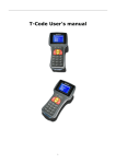
OWNERS MANUAL
AUDIBLE
SCIENCE
SERIOUSLY ADDICTIVE
by
A U D I O L A B O R AT O R I E S P T Y
LT D
Congratulations on choosing the Cobra tonearm.
The Cobra is a totally new design in tonearm technology
which has been developed by a team of dedicated music
lovers with qualifications in advanced engineering and
design, assisted by some of the most advanced computer
aided design software in the market today.
We ask that you take the time to read this manual carefully
to ensure that you not only enjoy optimum sound quality
from your Cobra, but also understand the care and
maintenance procedures required to keep your Cobra in
as-new condition for many years to come.
If you have any questions in reference to any part of your
Cobra at any time in the future, please feel free to contact
your Continuum Consultant for assistance.
Your Authorised Continuum Consultant is:
Serial Number:
Date of Manufacture:
audible science
audible science
page 2
TABLE OF CONTENTS
OUR DESIGN PHILOSOPHY .................. 6
TABLE OF
CONTENTS
DESIGN FEATURES
Arm Wand ............................................ 8
Headshell ............................................. 8
CAUTION
Refer servicing to
qualified personnel only.
Precautions
On Safety
Should any solid object or
liquid fall into the tonearm,
have it checked by your Factory
Authorized Consultant
On Placement
• Place the unit in a location with
adequate ventilation to prevent
heat buildup and prolong the life
of the unit.
• Do not place the unit near heat
sources, or in a place subject to
direct sunlight, excessive dust or
mechanical shock.
• Do not place anything near
Fingerlift .............................................. 10
Arm Lifter ............................................. 10
On Operation
Before connecting to phono
stage components, be sure to
follow component manufacturers
intructions.
Counterweight ...................................... 10
Vertical Bearing Motion........................... 12
Horizontal Bearing Motion ....................... 14
Azimuth Adjustment .............................. 14
Stylus Rake Angle (SRA) or (VTA) ............ 16
On Cleaning
Clean tonearm, and controls with
a soft cloth slightly moistened
with a mild detergent solution. Do
not use any type of abrasive pad,
scouring powder or solvent such
as alcohol or benzine.
Overhang Adjustment ............................ 20
Anti Skate or Bias Adjustment ................. 22
INSTALLATION
Why Set up is Critical ............................. 24
Installation & Set up .............................. 28
Positioning Central Tower on Turntable ..... 30
If you have any questions or
problems concerning your
Cobra tonearm, please contact
your Continuum Authorized
Installation Consultant
Distance of Spindle to Cross Arm Pivot ..... 34
VTA & SRA Set up .................................. 36
Mounting the Cartridge........................... 38
Mounting & Balancing the Arm ................ 38
Connecting and Adjusting Anti Skate ........ 42
Setting the Azimuth ............................... 48
the unit that might create RF
interference.
OWNER CARE & MAINTENANCE
Routine ................................................ 54
Specifications ........................................ 56
THE COBRA’S DESIGN HISTORY ..........
audible science
audible science
page 4
AIM FOR PERFECTION
OUR
DESIGN
PHILOSOPHY
Perfection, as a design concept, is not easily
defined. It maybe easier explained by listing the rules
it cannot be constrained by - budget, time, materials,
“Heart-shaped” counterweight
tradition, aesthetics, fashion or dogma.
Arm wire guide
AIM FOR PERFECTION, means we strive remove all the
constraints listed above, allowing us to concentrate
Arm wand
wholly on creating a product whose only constraint is
perfection itself. How close we get is for others to judge,
but we see no point aiming for anything less.
The Cobra is a perfect example of this design philosophy,
and was created because, after looking closely at the
state-of-the-art, we believed it could be better.
Any future products from Continuum Audio Labs will
follow this same philosophy - if we believe it can be
Integrated headshell
better, we will build it. If we believe we cannot improve
Arm lifter
it, we will enjoy and happily recommend the state-of-theart product. Because, our ultimate aim is the pursuit of
COBRA TONEARM ASSEMBLY
perfect sound reproduction.
audible science
audible science
page 6
COBRA DESIGN FEATURES
PARTS OF
YOUR COBRA
The Cobra represents the single biggest
breakthrough in performance of tonearm technology since
the groundbreaking designs of the 1980’s that changed the
way LP’s were played.
THE ARM WAND
Unique Monocoque construction using advanced fibre and
resin technology proprietary to Continuum Audio Labs.
The shape of the arm wand is optimised to reduce the
resonances inherent in the LP playback mechanism. There
is no need to apply additional damping material to the
Cobra as the polymer/fibre technology is by its very nature
extremely well damped.
THE HEADSHELL
The Cobra headshell is one piece with 12.5mm of
adjustment accepting standard M2.5 cartridge screws.
Please note: the depth of screws required is longer
than standard at 15mm minimum for cartridges with
integrated threads.
audible science
audible science
page 8
COBRA DESIGN FEATURES
CONT.
PARTS OF
YOUR COBRA
VTA fine vertical adjustment knob
THE FINGERLIFT
Vertical VTA vernier
The Cobra Finger lift is extended to the right of the head
shell at an angle designed to allow safe operation of manual
cueing. It is recommended that one use extreme caution
when cueing manually as stylus damage can result from
minor errors in handling. We recommend you use the arm
lifter to ensure safe operation of cartridge cueing.
THE ARM LIFTER
The arm lift is a standard industry format using silicon gel
damping. The height of the arm lifter is adjustable using
a standard metric allen wrench (supplied). The arm lifter
must be adjusted to suit the desired range of SRA or VTA
adjustment and relationship to turntable platter level.
Azimuth adjustment “Swash Plate”
THE COUNTERWEIGHT
The Cobra uses a neutral balance design to minimise
Vertical sliding cross arm
variations in tracking force over warps. Tracking force
remains constant when the arm is moved vertically.
To achieve neutral balance, the center of mass of the front
VTA locking thumb screws
end of the arm, the vertical pivot, and the tail end of the
arm should lie on a straight line.
audible science
audible science
page 10
COBRA DESIGN FEATURES
CONT.
PARTS OF
YOUR COBRA
THE COUNTERWEIGHT cont.
In addition, to minimize warp wow (pitch
changes as the stylus rides up and down over record
warps), the arm’s vertical pivot should be at the same
height as the record surface.
The Cobra uses a “heart like” shaped counterweight,
optimised for reduction of vibration.
To balance the arm a user uses a series of weights
which are added or subtracted from the underside of the
counterweight to get the cartridge into the correct zone.
An 8 Gram adjustable screw at the rear of the arm allows
for microscopic adjustments in the tracking force once
the cartridge is close to the correct weight range for the
counterweights. The counterweight also allows for some
“skewing” adjustment to forces in the azimuth plane.
THE VERTICAL BEARING MOTION
The Primary Pivot is a Precision Sapphire Vee Jewel with
Hardened Steel matching Central pivot. Used in the finest of
aircraft instruments this pivot technology does not require
heavy mass to be positioned over the pivot thus allowing for
exceptional tracking and response to groove modulation.
audible science
audible science
page 12
COBRA DESIGN FEATURES
CONT.
PARTS OF
YOUR COBRA
THE VERTICAL BEARING MOTION cont.
Secondary Pivot – Azimuth Stabilized with a Hardened Steel
Inverted pivot resting on a man made Sapphire “Swash
Plate”. This secondary pivot plays a crucial role in the
stability of the arm allowing for optimum placement of the
counterweight thus removing inertial problems associated
with alternative stabiliser designs.
THE HORIZONTAL BEARING MOTION
Two precision matched ABEC 7 vertically opposed bearings
with internal damping. Minimises precessional effects in
rotational plane to close to zero.
THE AZIMUTH ADJUSTMENT
Azimuth is adjusted by means of fine threaded Sapphire
Bearing swash plate. This is adjustable with micrometer
accuracy indicated on a clock face engraved on the azimuth
adjuster. Please ensure stylus is at rest when you adjust
azimuth.
Do not attempt to adjust during playback.
It is recommended azimuth is adjusted with a test record
and purpose designed scope or meter.
audible science
audible science
page 14
COBRA DESIGN FEATURES
CONT.
PARTS OF
YOUR COBRA
THE AZIMUTH ADJUSTMENT cont.
Please contact your Continuum Consultant if
you have any questions regarding these settings.
WARNING: If you use the wrong type of meter you
can destroy a cartridge coil mechanism. Digital
meters are especially prone to causing this “coil
burnout”. If you are unsure of the equipment you
are using to adjust azimuth please contact your
Authorised Continuum Consultant.
STYLUS RACK ANGLE (SRA) OR
VERTICAL TRACKING ANGLE ADJUSTMENT (VTA)
Continuum Audio Labs recognise that the original cutting
lathes used to make the master recordings have varying
degrees of calibration. We note that even minor changes in
SRA or VTA can have significant audible effects.
The Cobra offers the discerning audiophile an easy to adjust
mechanism to extract the last vestiges of performance from
your favourite LP.
To adjust the VTA, two thumbscrews at the rear of the main
arm mount are loosened to free the vertical sliding cross
arm. Then, the user turns the VTA fine vertical adjustment
audible science
audible science
page 16
COBRA DESIGN FEATURES
CONT.
PARTS OF
YOUR COBRA
STYLUS RACK ANGLE (SRA) OR VERTICAL
VTA fine vertical adjustment knob
TRACKING ANGLE ADJUSTMENT (VTA) cont.
Overhang locking bolt
knob clockwise to raise the arm pivot and counter clockwise
Arm wire guide
to lower the arm pivot.
8mm fine weight adjustment
Once the desired setting is reached the thumbscrews
are gently tightened to lock the arm mechanism in place
precisely. This system prevents any grub screw marking of
the main sliding shaft system. It is also triangulated in 3
planes to maximise stiffness.
This is adjustable during playback to dial-in your favourite
setting for various thickness of LP’s.
A broad scale vertical Vernier indicator is located on the
main arm support tower which is further enhanced by a fine
scale micrometer dial on the adjustment knob located at
the top of the main arm support tower.
Anti Skate weight adjustment
Anti Skate mechanism
A vertical movement of 4mm in the main pivot represents
“Heart-shape” counterweight
1 degree of SRA or VTA change. The Cobra arm design is
based on a standard stylus tip to top of cartridge dimension
of 18mm.
audible science
audible science
page 18
COBRA DESIGN FEATURES
CONT.
PARTS OF
YOUR COBRA
STYLUS RACK ANGLE (SRA) OR
VERTICAL TRACKING ANGLE ADJUSTMENT
(VTA) Other cartridge sizes can easily be used but the
majority of modern quality cartridge bodies and stylus
tip dimensions are set at or near a nominal dimension of
18mm.
The Cobra arm is very forgiving of setup errors so will
reward those who “seek the tweak” as well as those
listeners who prefer to “set and forget”.
As a general rule if the VTA is too high the sound will be
“lean and thin” and if the VTA is too low the sound will be
“boomy” and potentially “bass heavy”. This is of course
totally to user preference but will reward those seeking the
maximum from their LP collections.
OVERHANG ADJUSTMENT
The best setting is 221.7 mm (set during installation) but
allowance of 12.5mm adjustment in headshell slots allows
some minor variation in this distance. A single 8mm Socket
Head Cap Screw is tightened to lock the main arm support
mount into the correct location allowing for accurate VTA
adjustment without losing settings for overhang.
audible science
audible science
page 20
COBRA DESIGN FEATURES
CONT.
OPERATING
YOUR COBRA
ANTI SKATE OR BIAS ADJUSTMENT
The Cobra allows optimal anti skate force to be increased
from 8-12% of the tracking force across the playing surface
by use of correct geometry of the anti skate lever and the
ability to move the weight along the lever arm with an
additional ability to add or subtract weights.
The Arm wire guide is designed to minimise torque forces
affecting anti skate. We recommend a quality tool such as a
Wally Skater from WAM Engineering or a modulated groove
test disc such as Cardas Test Disc or Omni Disc available
from reputable LP suppliers is used to set antiskate.
CAUTION: In our opinion use of an unmodulated
groove to determine bias adjustment is an inaccurate
method of determining anti-skate force due to the
absence of modulated groove drag force .
audible science
audible science
page 22
INSTALLATION & SETUP
INSTALLING
& TUNING
YOUR COBRA
WHY SETUP IS CRITICAL
VTA locking thumbscrews
If a phono cartridge is not correctly setup, damage can
occur to your precious record collection, and you will
Overhang locking bolt
miss out on the incredible realism that good vinyl can
reproduce.
The design of the Cobra tonearm allows for minute
adjustments to be made to ensure the stylus tip is
correctly positioned in all planes.
The positioning of the stylus tip in the spinning record
groove is referred to as tracking ability.
Cross arm
It is defined as the maximum velocity at which the stylus
tip can move back and forth tracing the audio signal
Cut away view of Cobra
before it starts to skip. A tracking failure is referred to as
mistracking.
Serious mistracking, when the high mass of the stylus
causes it to veer out of control, can permanently damage
a record by altering the signal patterns in the record
groove. Such damage can occur in just one play.
audible science
audible science
page 24
INSTALLATION & SETUP
CONT.
INSTALLING
& TUNING
YOUR COBRA
WHY SETUP IS CRITICAL The stylus tip
traces the musical signal inscribed in the record groove,
which can contain modulations as small as a millionth of
an inch. Therefore small adjustments to the stylus tip’s
position will alter the sound significantly.
If you are unfamiliar with cartridge setup procedures
please contact your Continuum Audio Labs Authorised
Installation Consultant for assistance.
With the almost ubiquitous nature of the internet there
are many resources available for learning about cartridge
setup.
However we urge caution in following some of the
recommendations found on user groups and bulletin
boards. Some of these tips are not based on sound
engineering principles.
Please refer to manufacturer instructions in all cases
before trying any “tweaks”. Failure to follow manufacturer
instructions can result in a voiding of any warranties.
audible science
audible science
page 26
INSTALLATION & SETUP
CONT.
INSTALLING
& TUNING
YOUR COBRA
INSTALLATION
Central arm tower
86.95mm
This Manual is for Factory Authorized Installers and
technically proficient users who are familiar with phono
232.81mm
cartridges and tonearm installation terminology and
concepts.
The main steps of installing the Cobra are:
Turntable spindle
Distance of spindle to central arm tower = 251.60mm
1.
Disassembly to enable mounting to turntable.
2.
Installation of the central tower mount.
3.
Re-assembly of main arm components
4.
Adjustment and lock down of overhang dimension
5.
Adjustment of pivot height relative to platter height
7.
Installing Cartridge on Wand
8.
Installing Wand on pivot assembly
9.
Balancing the wand
9.
Connecting antiskate string
9.
Adjusting of anti skate force
10. Adjustment of azimuth for initial cartridge setup
audible science
audible science
page 28
INSTALLATION & SETUP
CONT.
INSTALLING
& TUNING
YOUR COBRA
Central Tower
DISASSEMBLY & ASSEMBLY OF THE COBRA
The Cobra comes to you with the main components
assembled, and needs to be disassembled for installation.
Cross arm - slide inside the Main Body
before inserting the Central
Tower into the Main Body
DISASSEMBLY FOR MOUNTING PROCEDURE
Use a 6mm allen key to undo the overhang locking bolt
on the top of the main body. Next, loosen the two VTA
locking thumb screws, and slide the central tower off the
main body and cross arm.
Main Body
with Cross arm
NOTE: take note of how the central tower fits
through the cross arm, for when you have to
reassemble it.
You are now ready to mount the Central Arm Tower
to the turntable.
POSITIONING CENTRAL TOWER ON TURNTABLE DISTANCE OF SPINDLE TO CENTRAL ARM TOWER
Once you have marked the center point of the Central
Arm Tower you will need to drill 4 equispaced holes to
Fully assembled
audible science
bolt the arm mount onto the plinth.
audible science
page 30
INSTALLATION & SETUP
CONT.
INSTALLING
& TUNING
YOUR COBRA
DISTANCE OF SPINDLE TO CENTRAL ARM TOWER
We recommend you use 4mm Socket Head Cap Screws
VTA thumbscrews
and professionally drill and tap the plinth or armboard to
Vernier scale
allow the arm to be bolted directly to the plinth.
The 4 equispaced holes need to be drilled on a 56mm
PCD (Pitch Circle Diameter) to suit M4 screws. We
recommend these 4 holes are drilled cardinally (North
South East West) but depending on your unique
installation these can be drilled in any orientation that
clears infrastructure obstacles.
Note: If the plinth requires a cutout to access a
sub-chassis then the main arm mount requires a
72-80mm hole to be cut to allow for clearance.
Once you have drilled and tapped the required holes you
can bolt the Central Arm Tower down. You are now ready
to place the main arm mount and crossarm with pivot
assembly on to the Central Arm Tower and lock down the
Spindle to Pivot or overhang distance.
audible science
audible science
page 32
INSTALLATION & SETUP
CONT.
INSTALLING
& TUNING
YOUR COBRA
SPINDLE TO MAIN PIVOT DISTANCE (OVERHANG)
Overhang is adjusted by positioning the main pivot in
Turntable spindle
Cross arm pivot
relation to the turntable spindle.
The Cobra uses an offset crossarm that holds the main
pivot. This crossarm can be rotated in a shallow arc that
allows for variances in turntable plinth designs.
The optimum distance from pivot to spindle is 221.7 mm.
Viewing the platter from above (Plan View) use a metric
ruler to measure from the spindle to the main arm pivot
(located on the crossarm) a distance of 221.70mm.
Distance of spindle to cross arm pivot = 221.70mm
Next tighten the 8mm Hex Head Overhang Locking Screw
using a 6mm Allen Key. Do not overtighten. This screw
compresses the main arm mount and the main arm body
which holds the crossarm and pivot. Once this screw
is tightened the overhang is firmly set. This setting is
maintained even when you are adjusting the VTA.
audible science
audible science
page 34
INSTALLATION & SETUP
CONT.
INSTALLING
& TUNING
YOUR COBRA
VTA & SRA SETUP
Cobra central arm
bearing cup
HOW TO ADJUST VTA AND SRA
At the rear of the main arm mount there are two
thumb screws. These need to be loosened in order for
the crossarm to be raised or lowered using the VTA
adjustment knob at the top of the main arm mount.
Cobraʼs “heart-shaped”
counterweight with
removeable weights
There is a broad scale vernier on the rear of the main
arm mount. This is complemented by a dial scale at the
top of the VTA adjustment knob.
Once you have set the main arm pivot at the same level
as the platter you can mark the position on both the rear
vernier and dial scale on the adjustment knob using a
marker pen or coloured nail varnish. Experienced Cobra
users often use different coloured marks to identify
preferred settings for varying thickness LP’s.
Cross arm pivot
Use a ruler edge to sit on the platter and let it protrude
over the edge to line up over the arm pivot (remove the
wand to do this).
audible science
audible science
page 36
INSTALLATION & SETUP
CONT.
INSTALLING
& TUNING
YOUR COBRA
HOW TO ADJUST VTA AND SRA cont.
Raise or lower the cross arm till the main pivot touches
the edge of the ruler. This is the level point from which to
adjust the VTA up or down.
Cobra one piece headshell
use supplied screws to
mount cartridge
To tighten the thumbscrews use only light finger force
as these thumbscrews can exert many kilograms of
pressure.
HOW TO MOUNT THE CARTRIDGE
The Cobra headshell is a one piece contruction and
accepts all standard 12.7mm cartridges, MC and MM.
Mount cartridge in the headshell according to the
manufacturers instructions. Use the cartridge mounting
screws supplied with your Cobra.
Do not force or overtorque the M2.5 screws.
Connect the Cartridge pins to the arm wire following the
cartridge manufacturers instructions.
audible science
audible science
page 38
INSTALLATION & SETUP
CONT.
INSTALLING
& TUNING
YOUR COBRA
HOW TO MOUNT AND BALANCE THE ARM
To mount the arm wand, gently place the central arm
bearing cup directly on the main pivot on the cross arm.
The tone arm now sits in position, held in place by the
mysterious power of gravity.
Balancing any tonearm is a delicate operation requiring
steady hands and a set of scales, acurate to .01 of a
gram. The “heart-shaped” counter weight on the Cobra is
fixed in distance from the arm pivot.
Under the counter weight is a hollow section where
weights of varying thickness can be removed or attached
to balance the cartridge. These weights are used to
establish the tracking force close to optimum.
Final adjustment to tracking force is accomplished by
winding the 8mm fine weight adjustment screw at the
rear of the arm. Winding in, increases tracking force,
winding out decreases the tracking force.
audible science
audible science
page 40
8mm fine weight
adjustment screw
INSTALLATION & SETUP
CONT.
INSTALLING
& TUNING
YOUR COBRA
Anti skate lever
weight thumbscrew
HOW TO CONNECT AND ADJUST THE ANTISKATE
The Cobra uses a specially designed geometry to alter the
force of the bias across the surface of the record from 812% of the tracking force.
Close up of anti skate cord
attached to anti skate lever
The Cobra Arm Wand has a triangular shaped antiskate
“cam” on the underside of the arm, around the main
bearing cup. You will notice a lightweight cord attached
to this cam. The O-ring on the end of the cord needs to
be slid over the hook on the end of the anti skate lever.
Once this cord is attached the bias can be adjusted by
changing the position and the mass of the weight on the
end of the anti skate lever.
Anti skate cord
attached to the
anti skate cam
Loosen and slide this weight up the lever to reduce
bias, sliding it down the lever to increase the bias.
Factory settings of the weight are close to optimum,
but if you need to add further weight, undo the thumb
screw completely and add one of the supplied 3mm
broad washers as required. Do not overtighten as the
mechanism is designed to be very light to reduce inertia.
audible science
audible science
page 42
INSTALLATION & SETUP
CONT.
INSTALLING
& TUNING
YOUR COBRA
HOW TO ADJUST THE ANTISKATE cont.
The bias should be adjusted according to the tracking
force. We recommend you set the bias by use of an
appropriate test record, ie. those with tracking bands.
Do not use unmodulated grooves as they do not
create accurate vector forces.
Most test records use a principle of mistracking to identify
Sapphire “swash plate”
& secondary pivot
bias adjustment. We recommend you also use tools such
as a Wally Skater from WAM Engineering to set bias.
If mistracking is apparent, adjust the bias until minimum
mistracking is heard in both channels. If mistracking
appears in the right channel only, the bias is too low.
Move the weight down or add mass to the antiskate lever
arm. If it appears in the left channel only, the bias is too
high. Move the weight up or add mass to the antiskate
Azimuth “swash plate”
locking grub screws
lever arm. If mistracking appears equal on both channels,
the trackability limit of the cartridge has been reached.
You may be able to reduce mistracking further
by increasing the tracking force to the maximum
recommended by the cartridge manufacturer.
audible science
audible science
page 44
INSTALLATION & SETUP
CONT.
INSTALLING
& TUNING
YOUR COBRA
Arm wire guide
HOW TO ADJUST THE ANTISKATE cont.
If you are unable to adjust to the correct range, try
adding or subtracting the small washer weights from the
lever. This is done by undoing the thumbscrew completely
Arm wire
and adding or subtracting the 12mm penny washers with
a 3mm hole. These washers are supplied in your arm kit.
Please contact us if you require replacements.
Please note that arm wires can play a significant part in
bias forces. That is why we have provided an arm wire
guide to train the arm wire to minimize torque. Ensure
the armwire is hooked through the arm wire guide centre
“hook” and held directly over the main arm pivot.
The arm wire exits right above the main pivot for this
reason. The arm wires are also wound in opposing
directions to minimize twisting forces. This then allows
the antiskate lever to work at an optimum level.
NOTE: Mistracking is most easily observed by use
of an oscilloscope, and is a superior method of
calibration.
audible science
audible science
page 46
INSTALLATION & SETUP
CONT.
INSTALLING
& TUNING
YOUR COBRA
HOW TO ADJUST THE AZIMUTH cont.
The azimuth must be adjusted with the cartridge at rest
or using an old record and the cartridge cover installed.
WARNING: DO NOT ATTEMPT TO ADJUST THE
AZIMUTH DURING PLAY AS SERIOUS DAMAGE TO
THE STYLUS COULD OCCUR.
The Cobra uses two pivots to stabilise the arm in the
vertical plane. The main center pivot is fixed.
The secondary pivot is adjustable. This secondary pivot
can be raised or lowered by adjusting the sapphire
“swash plate” that it sits on. By raising or lowering
this secondary pivot the arm wand is rotated in the
longitudinal dimension resulting in the stylus azimuth
being adjusted.
The “sapphire” plate can be wound down (clockwise
rotation when viewed from above) or wound up
(anticlockwise when viewed from the top). There are two
azimuth swash plate locking grub screws which need to
be loosened before adjusting.
audible science
audible science
page 48
INSTALLATION & SETUP
CONT.
INSTALLING
& TUNING
YOUR COBRA
HOW TO ADJUST THE AZIMUTH cont.
They are located at right angles to the azimuth adjusting
sapphire ring holder.
If you look at the arm from the front on you will see a
brass coloured secondary pivot on the right hand side (at
the rear of the arm where the main pivot is).
This is the secondary pivot that rests on the sapphire
ring. By raising or lowering the sapphire ring you will
adjust the azimuth by means of this secondary pivot.
If we view the cartridge front-on from the headshell as
an indicator for the direction of azimuth, the following
applies: winding the sapphire ring down (clockwise) the
right hand side of the cartridge will dip down.
Winding the sapphire ring up (anticlockwise), viewed
front-on, the left hand side of the cartridge will dip down.
There are a series of small dashes and dots on the
azimuth adjuster.
audible science
audible science
page 50
INSTALLATION & SETUP
CONT.
INSTALLING
& TUNING
YOUR COBRA
HOW TO ADJUST THE AZIMUTH cont.
These are used to set the initial reference point. Then
when you adjust the azimuth you can do so with accuracy
and repeatability.
Experienced Cobra users place permanent marker ink or
coloured nail polish into one of the dashes on the azimuth
adjuster next to the stationary index mark.
This gives you the ability to move a few minutes either
way for final adjustment and take note for cartridge to
cartridge variances.
When complete you can lock the azimuth swash plate by
tightening the 4mm grub screws on the cross arm which
located at 90 degrees to the azimuth swash plate.
audible science
audible science
page 52
OWNER CARE & MAINTENANCE
CARING
FOR YOUR
COBRA
Your Cobra tonearm is a delicate piece of
equipment, and care needs to be taken when using and
cleaning it. Below are recommendations for keeping your
Cobra at its optimum performance.
CARING FOR METAL SURFACES
The metals we have chosen because of their superior
sound qualities are susceptible to being scratched.
Do not use any window cleaning solutions, silicon
based polish, abrasive pads, scouring powder or
solvents such as alcohol or bezine to clean your
Cobra. Your Continuum Consultant can advice you
on what products available in your area are suitable
to use for cleaning.
CLEANING THE TONEARM
The tonearm can be cleaned using a soft, camera-lensquality, cleaning chamois.
BEARING MAINTENANCE
The bearing is fully enclosed and requires no owner
maintenance.
audible science
audible science
page 54
COBRA SPECIFICATIONS
THE
COBRA
SPECS
• Effective Length: (from stylus to pivot point) 239mm
• Overhang: (from Stylus to spindle Centre) 17.3mm
• Offset: (Headshell Offset in degrees) 23 Degrees
• Cartridge Fixing Centres: 12.7mm for standard M2.5
socket head cap screws
• Mounting Distance: (from pivot to spindle centre) 221.7
• Arm Mount Hole Pitch: 76mm by 4 equidistant cardinal
points for 4mm metric socket head cap screws.
NOTE: Arm mount centre is offset from arm pivot
by 60mm which allows for significant adjustment
for mounting on various turntable systems. So
whilst the 76mm hole PCD is similar to the Graham
mount the location of the holes is further away.
An optional mounting plate adaptor is available for
customised mounting requirements.
• Depth Below mounting surface: 0mm (no items
extend below the surface of standard Cobra mount).
• Radial Clearance for Counterweight: 90mm
audible science
audible science
page 56
COBRA SPECIFICATIONS
CONT.
THE
COBRA
SPECS
• Clearance from plinth surface to top of
arm mount: 150-200mm preferred for arm wire training.
• Cartridge Weight Range: 0-20Grams – Adjusted by
Mass Addition Subtraction of Supplied Weight Adjustment
Kit. Fine tuned by 8 Gram sliding set screw for 0.01
Gram increments.
• VTA Adjust: – Yes
• Azimuth Adjust: - Yes
• Horizontal Natural Frequency: 8.1Hz
(Note: Calculated on Finite Element Analysis)
• Vertical Natural Frequency: 8.1Hz
(Note: Calculated on Finite Element Analysis)
• NULL POINTS: 66.0mm Inner 120.8mm Outer
• Audio Lead: Supplied with a 33 AWG pure copper litz
design as 1.5 meter standard in our preferred
configuration of single RCA Termination from Cartridge
Clip to RCA Male Connector. Other Arm leads are available
and are easy to replace and can be supplied on request.
• DIN Plugs: can be fitted as an optional extra.
• Complete Arm Weight: 1Kg Nominal
audible science
audible science
page 58
Dr. Neil McLachlan - Professor at RMIT University’s
COBRA’S DESIGN HISTORY
School of Architecture & Design.
COBRA’S
DESIGN
HISTORY
Neil worked closely with Mark on the reshaping and
The technology used to design the Cobra arm
acoustic modelling and design, and developed new and
is more in the domain of advanced military,
innovative solutions to the some very old problems
aeronautical and automotive environments but is critical to
associated with analogue sound reproduction.
breaking the “sound barrier” in LP performance.
Wally Malewicz - Bachelor of Engineering (Mechanical),
Many years ago a team of designers and engineers under
Senior Engineering Consultant.
the leadership of a talented Australian designer Ben Lexcen
Wally is well known for his dedication to developing
revolutionized the America’s Cup yachting challenge by
tonearm geometry. His “Wally Phono Tools” are used
developing a “winged keel” using advanced software design
worldwide by discerning audiophiles. Wally worked
tools. This revolutionary “shape optimised” keel allowed
closely with Mark Doehmann developing the anti-skate
superior performance to be extracted from the associated
mechanism and alignment geometry for the tonearm.
hull technology. At the time it “broke all the rules” and
proved itself in the field of ocean racing.
Michail Barabasz - Bachelor of Engineering (Electrical)
Michail develop the unique “heart-shaped” counterweight
In similar fashion the Cobra arm presents a revolutionary
system for the Cobra.
breakthrough in arm design for another pursuit of ultimate
performance – the quest for perfect sound. The challenges
Warwick Freemantle - Bachelor of Arts (Economics),
are no less daunting as the combinations and permutations
Quality Assurance & Production Process Management.
are nearly endless.
Warwick designed the wiring system for the Cobra using
a unique bend of natural and high tech materials.
What the engineers at Continuum Audio Labs did was to
throw out the “rulebook” and question the accepted wisdom
of prior tonearm designs and choices of materials.
audible science
audible science
page 60
Continuum Audio Labs chose to “go back to the drawing
COBRA’S DESIGN TEAM
board” and examine the physics at play in analogue vinyl
Many very intelligent minds were brought
replay systems. The physics were made visible by the use
together to push the envelope of what was
of Finite Element Analysis software. The result was then
imagined possible for tonearm technology,
worked back to a practical implementation of currently
and we would like acknowledge each one of them now.
COBRA’S
DESIGN
TEAM
available materials and fabrication techniques.
Mark Doehmann - Chief Designer
This methodology is proven to advance technology not by
Marks’ passion for analogue sound reproduction combined
increments but by leaps and bounds.
with his background in aeronautical and advanced
software engineering and advanced materials fabrication
What you are about to hear is a result of some very radical
techniques was used to transform his vision for the Cobra
thought processes and development methodologies.
from the “virtual world” to the end product.
You will ultimately be the judge of whether this design
David Payes - Chairman, Continuum Audio Labs
approach delivers an advancement of the state of the art.
David was the catalyst for the development of the Cobra,
Many experienced audiophiles have validated our design
and created the financial and creative freedom to push
choices. Music lovers who have described the sound
the envelope. David is a passionate audiophile and has
emanating from a Cobra as being the closest they have
had extensive input with technical design issues.
been to a master tape or live performance.
Dr Murali Murugasu MB.ChB. MBA
We hope you enjoy the Cobra as much as we do.
Murali is part of the core design team at Continuum
It’s seriously addictive!
Audio Labs. His day to day involvement ensures that
our products meet various regional market requirements
and ensures that they works in harmony with other high
quality components to deliver a complete solution.
audible science
audible science
page 62
COBRA’S DESIGN TEAM
COBRA’S
DESIGN
TEAM
John Loton - Bachelor of Engineering
(Aeronautical) Advanced Physics & Structures Design.
John was instrumental in the “challenging process” where
original “seed ideas” were subjected to an intense peer
review process to extrapolate potential “blind alleys”
Prof. Josef Tomas - Reshape Software and
Mechanical Engineering Design.
Josef created the Reshape™ software that allowed us
to move resonances inherent in the Cobra’s unique
shape into regions where they could be controlled and
effectively managed.
Dr. Glen Wolff - Advanced Systems Engineering.
Glen holds a PhD (Electrical Computer Engineering) and
his expertise was sought to deal with the complex use of
organic materials and their application on the Cobra.
We would also like to thank everyone involved in the
manufacturing process, who’s names and details can be
found on our website - www.continuumaudiolabs.com
audible science
audible science
page 64