1
PVIA!1
Single Zone VIA!® Wall Plate
Installation Manual
Important Information
NOTE: This equipment has been tested and found to comply
with the limits for a Class B digital device, pursuant to Part 15
of the FCC Rules. These limits are designed to provide reasonable protection against harmful interference in a residential
installation. This equipment generates, uses and can radiate
radio frequency energy and, if not installed and used in accordance with the instructions, may cause harmful interference
to radio communications. However, there is no guarantee that
interference will not occur in a particular installation.
If this equipment does cause harmful interference to radio or
television reception, which can be determined by turning the
equipment off and on, the user is encouraged to try to correct
the interference by one or more of the following measures:
• Reorient or relocate the receiving antenna.
• Increase the separation between the equipment and receiver.
• Connect the equipment into an outlet on a circuit different
from that to which the receiver is connected.
• Consult the dealer or an experienced radio/TV technician for
help.
Caution: Changes or modifications not expressly approved by
ELAN could void the user’s authority to operate this equipment.
ELAN HOME SYST E M S
PVIA1
Table of Contents
Introduction .........................................................................3
Features ...........................................................................3
Front Panel Call-Out ........................................................4
Rear Panel Call-Out ........................................................5
System Design .....................................................................6
Wire Runs ........................................................................7
Maximum Wire Length ....................................................8
Applications .....................................................................9
Stand-Alone .....................................................................9
Stand-Alone Expanded ...................................................10
Home Theater Serial Control ..........................................11
S12 Series ........................................................................12
S8 Series ..........................................................................13
S6 Series ..........................................................................14
Connections .........................................................................15
Rear Panel Connections .................................................15
Standalone Connections ................................................16
S12 Series Connections ..................................................17
S8 Series Connections ....................................................18
S6 Series Connections ....................................................19
Chaining PVIA Wall Plates ..............................................20
PVIA1 Wall Plate To SPP Application .............................20
PVIA1 Wall Plate To PVIA4 Application ..........................21
PVIA1 Wall Plate To PVIA1 Valet Application ................22
Composite Video Connections .......................................24
IR Out Front .....................................................................25
IR Out To IR Block ...........................................................26
IR Out Rear ......................................................................27
Power Connection ...........................................................28
Power Sense ....................................................................29
© 2008 ELAN Home Systems • All Rights Reserved
Page 1
PVIA1
ELAN HOME SYST E M S
Troubleshooting ...................................................................30
Appendix A: Specifications ...............................................31
Warranty ...................................................................Back Page
Page 2
© 2008 ELAN Home Systems • All Rights Reserved
ELAN HOME SYST E M S
PVIA1
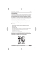
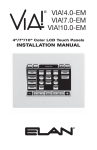
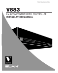
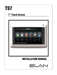
Introduction
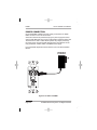
The PVIA®1 Wall Plate Precision Panel is designed to simplify the installation
of ELAN VIA!® Touch Panels and provide a reliable, logical connectivity solution. Designed to work with all in-wall models (4.0EM, 7.0EM, 10.0EM), the
PVIA1 has provisions for each connection type required for a complete inwall installation. For multiple VIA! Touch Panel installations, PVIA®4, PVIA®10
and SPP Precision Panels may be used to ensure secure connections and
help save time when dealing with complex wiring jobs.
The PVIA1 Wall Plate is needed for each VIA! Touch Panel in-wall model.
•Use in stand-alone systems wherever a VIA! Touch Panel is needed
•Use in ELAN S Series systems wherever a VIA! Touch Panel is needed
•Use for local system control - perfect for Home Theaters!
Features
•Provides Power, IR & Video routing to a single VIA! Touch Panel
•IR output port
•Status Sense input
•Video input (Composite connector-to-F connector video pass-through)
•Rear panel connector for S Series Precision Panel interface
•Single-gang Decora® format
•PWR1 plug-in power supply included
A second version of the PVIA1 (PVIA1 Valet) is used for VIA! Valet®Touch
Panel installations. The PVIA1 Wall Plate version is required for use with the
ELAN VIA! SC-4 and SS1 System Station RS-232 controllers. There are also
instances where the two PVIA1 versions are used together.
Figure 1-1: PVIA1 In-Wall
© 2008 ELAN Home Systems • All Rights Reserved
Page 3
PVIA1
ELAN HOME SYST E M S
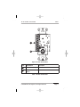
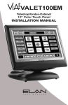
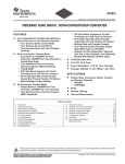
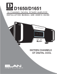
PVIA1 Wall Plate Front/Rear Panel
1
4
2
5
3
Figure 1-2: Front Panel Callout
Item
Input/Output
Description
1
IR Output
3.5mm Mono Mini jack
2
9 VDC Power Sense In
9 VDC PWR Cube Connection
3
Composite Video In
Coaxial Video Cable Connector
4
16 VDC Power Jack
16 VDC 1 Amp PWR1
Connection
5
RJ-45 Output
System RJ-45 Cable Jack
Table 1-1: Front Panel Callout
Page 4
© 2008 ELAN Home Systems • All Rights Reserved
ELAN HOME SYST E M S
PVIA1
1
2
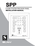
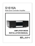
Figure 1-3: Rear Panel Callout
Item
Input/Output
Description
1
CAT-5 Terminal Strip
Terminate CAT-5 conductors
2
Coaxial Video
Output
Coaxial Video Cable Connector
Table 1-2: Rear Panel Callout
© 2008 ELAN Home Systems • All Rights Reserved
Page 5
PVIA1
ELAN HOME SYST E M S
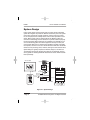
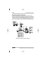
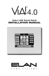
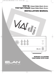
System Design
Proper system design ensures that all parts of a whole-house audio/video
system work together to provide the desired results. Each part of the system
(source A/V components, keypads, speakers, and the multi-room controller, for example) must be carefully chosen and a location specified for each
device. Wiring needs must be carefully planned for. Building codes and
contruction methodology must be factored in to provide a safe and properly
functioning system. Before beginning any installation, it is advisable to consult a set of building plans and a list of equipment and map out each part
of the system. Make sure to carefully locate speakers, keypads, touchpads,
touch panels, and wire runs so as to avoid interference with other household
devices such as plumbing, doors, windows, and high-current electrical wires.
System Design is typically comprised of Prewire, Rough-In, and Trim-Out.
The following sections will describe each phase of the installation process
as they pertain to installing ELAN VIA! Touch Panels and the PVIA1 Precision
Panel specifically.
VIA! 40/70/100EM
Rear
Keypads
Front
TM
VIA!-SC4
or
SS1
A/V Sources
Olé
Touchpads
COM2
External IR
Receivers
S8.6AV / S6 / S12
Sensors
AUDIO SENSOR
Triggered
Devices
SPP
(side view)
External Amplifier
SPK
SPK
SPK
SPK
PVIA1 Inwall
Figure 2-1: System Design
Page 6
© 2008 ELAN Home Systems • All Rights Reserved
ELAN HOME SYST E M S
PVIA1
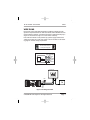
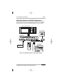
WIRE RUNS
Runs of Cat-5 for IR and Data transmission and RG-6 or RG-59 for Video
signals are required between the VIA! Touch Panel, PVIA1 Wall Plate and the
central equipment location. If the VIA! Touch Panel is powered locally only a
single run of Cat-5 and a single run of coax will be necessary.
If the VIA! Touch Panel is to be powered by a power supply located at the
“head-end” location of a multi-room system, refer to the table on the following page for minimum wiring requirements.
VIA!NET
EXT IR
TO SENSE INPUTS
1
2
SS/SC4
3
USE STEREO 3.5mm PLUGS ONLY
4
5
6
3
4
7
8
ZONE
ZONE
1
5
TRIGGERS
1
2
5
6
ZONE
2
ZONE
ZONE
3
ZONE
POWER
+
6
ELAN Precision Panels save
time and make sense out
ZONE
--
16VDC / 10A
4
7
ZONE
8
16VDC / 4A
16VDC/1.5A
of complex wiring jobs!
Standard ELAN RJ-45 Pin-Out
FRONT
PIN # COLOR CODE
1
2
3
4
5
6
7
8
TAB
BLUE
WHITE/BLUE
ORANGE
WHITE/ORANGE
GREEN
WHITE/GREEN
BROWN
WHITE/BROWN
CABLE
Figure 2-2: ELAN RJ-45 Pin-Out
VIA! 40/70/100EM
PWR1
ELAN S12
Cat-5
TV
RG-59
PVIA1
Valet
Figure 2-3: Wiring Overview
© 2008 ELAN Home Systems • All Rights Reserved
Page 7
PVIA1
ELAN HOME SYST E M S
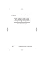
These are the maximum wire run lengths when using the following cables to
provide power to the VIA! Touch Panel when the power supply is located in
the “head-end”:
24 AWG
Cat-5
18 AWG
Stranded
16 AWG
Stranded
14 AWG
Stranded
110 ft.
225 ft.
360 ft.
575 ft.
Table 2-1: Maximum Wire Lengths
Page 8
© 2008 ELAN Home Systems • All Rights Reserved
ELAN HOME SYST E M S
PVIA1
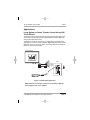
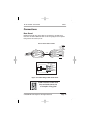
Applications
Local System or Home Theater Control Using VIA!
Touch Panels
The VIA! Touch Panel utilizes Cat-5 and RG-59 or RG-6 coaxial cable for the
Transmission of Power, IR and Video signals between the PVIA1 Wall Plate
and the VIA! In-Wall Touch Panel.
The VIA! Touch Panel can be used for any stand-alone (non-ELAN) system
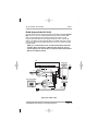
application or as a Home Theater controller. Figure 2-4 below shows a basic
application using one VIA! Touch Panel, a PVIA1 Wall Plate and an ELAN IR
Emitter to control an A/V Receiver.
VIA! 40/70/100EM
PVIA1
To Back
of PVIA1
Inwall
PWR1
ELAN
IR Emitter
A/V Receiver
Figure 2-4: Stand-Alone Application
NOTE: When IR is connected to the front of the PVIA1 In-Wall, IR
pass-through on the rear is disabled
© 2008 ELAN Home Systems • All Rights Reserved
Page 9
PVIA1
ELAN HOME SYST E M S
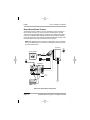
Stand-Alone System- Expanded
Stand-alone systems (without an ELAN multi-room controller) can be as
simple as one VIA! Touch Panel controlling one IR source, or as complex as a
VIA! Touch Panel, System SS1, ELAN Sensors all controlling many IR sources
and Serial devices as shown in Figure 2-6. Figure 2-5 below shows a VIA!
Touch Panel, A PVIA1 Wall Plate, four VIA!70EMs and a PVIA4 Wall Plate controlling a stack of A/V gear. See VIA!Tools for additional programming details.
VIA! 40/70/100EM
PVIA1
PWR1
To Back
of PVIA1
Inwall
Digital Music Server
PVIA4
IR Emitter
2
1
1
PVIA-4
3
2
9 VDC
SENSE
INPUTS
+16VDC
POWER
3
ALL
IR
OUT
4
Satellite
SYS
SENSE
4
TO VIA!NET
PWR2
VIDEO
IN
16 VDC/
4A
IR Emitter
1
2
3
4
PWR4
DVD
Amplified IR
Connection Block
IR Emitter
VIA!70EM X 4
Figure 2-5: Stand-Alone Expanded Application
Page 10
© 2008 ELAN Home Systems • All Rights Reserved
ELAN HOME SYST E M S
PVIA1
Stand-Alone System w/ RS-232 Subsystems
This application adds the control capabilities of an SS1 System Station to
control a projection screen and drapes using relays and a 1 and 2-way RS232 control devices. Consult the SS1 System Station manual for details.
Relay Controlled Devices (x8)
Screen
Drapes
VIA! 40/70/100EM
Relay
SYSTEM SS1
NO
COM
NO
NC
GND
PWR
NO
COM
NC
GND
PWR
NO
COM
NC
COM
NC
GND
PWR
GND
PWR
NO
COM
NC
GND
PWR
NO
COM
NO
COM
NC
GND
PWR
NO
NC
COM
NC
GND
PWR
GND
GND
PWR
PWR
®
LEXINGTON, KY • MADE IN CHINA
MODEL: SS1 SYSTEM STATION
DC RELAY PWR
HOST RS-232
RELAY 1
RELAY 2
COM 1
COM 2
COM 3
COM 4
RELAY 5
RELAY 6
COM3
COM4
WARNING: DO NOT REMOVE COVER.
NO USER SERVICEABLE PARTS INSIDE.
REFER SERVICE TO ELAN-APPROVED
SERVICE TECHNICIAN.
RELAY 8
RELAY 7
SENSE INPUTS
COM1
COM2
HOST
ELAN
ELAN RS-232
RELAY 4
RELAY 3
1
2
3
ALL IR OUTPUT
1
2
IR OUTPUTS
4
3
5
6
4
5
6
EXT IR INPUT
7
8
9
11
12
VIA-NET
DOWNLOAD
LINK
RX/TX
10
PWR1
SS1
POWER
12VDC
0.5 AMPS
+
-
IR-LINK
ETHERNET
IR
PWR
ENABLE
Sense Inputs (x6) IR Outputs (x12)
RS-232
PVIA1
Home Theater
Components
AUDIO SENSOR
CONTACT SENSOR
LED/LIGHT SENSOR
1 & 2-Way
RS-232 Controlled
Devices (x4)
Local Port
IR Emitter
ELAN® SENSE
Sensors
IR Emitter
IR Emitter
Figure 2-6: Stand-Alone System w/ SS1 System Station
© 2008 ELAN Home Systems • All Rights Reserved
Page 11
PVIA1
ELAN HOME SYST E M S
System12 (S12)
ELAN’s SPP Precision Panel for the System12 Multi-Room A/V Controller
(S12) makes quick work out of configuring a VIA! Touch Panel to control S12
zones. A PVIA1 Wall Plate may be used when adding a VIA! Touch Panel
with an S12 for local power and local source control. The Figure 2-7 below
shows one VIA! Touch Panel, one PVIA1 Wall Plate, ten VIA!70EM Touch
Panels, and an SPP connected to an ELAN S12.
VIA!40/70/100EM
PVIA1
PWR1
To Back
of PVIA1
Inwall
VIA!70EM X 10
VIA!NET
EXT IR
TO SENSE INPUTS
1
2
SS/SC4
3
USE STEREO 3.5mm PLUGS ONLY
4
5
6
1
2
3
4
5
6
7
8
ZONE
ZONE
1
5
TRIGGERS
ZONE
2
ZONE
POWER
ZONE
3
ZONE
+
6
ZONE
--
16VDC / 10A
4
7
PWR10
ZONE
16VDC
10.0A
8
16VDC / 4A
16VDC/1.5A
SPP
S12
Figure 2-7: S12 Application
NOTE: A PS12 Precision Panel may also be used with System12
applications.
Page 12
© 2008 ELAN Home Systems • All Rights Reserved
ELAN HOME SYST E M S
PVIA1
System8 (S8)
The VIA! Touch Panel flexibility makes it a good candidate for System8 (S8.6)
applications. A PVIA1 Wall Plate may be used when adding a VIA! Touch
Panel with an S8 for local power and local source control. The Figure 2-8
below shows a VIA! Touch Panel, a PVIA1 Wall Plate, ten VIA!70EMs and a
SPP Precision Panel configured for use with an ELAN S8.6.
VIA!40/70/100EM
PVIA1
PWR1
VIA!70EM X 10
To Back
of PVIA1
Inwall
VIA!NET
EXT IR
TO SENSE INPUTS
1
2
SS/SC4
3
USE STEREO 3.5mm PLUGS ONLY
4
5
6
1
2
3
4
5
6
7
8
ZONE
ZONE
1
5
TRIGGERS
ZONE
2
ZONE
3
ZONE
6
POWER
ZONE
+
ZONE
--
7
PWR10
ZONE
16VDC / 10A
4
8
16VDC
10.0A
16VDC / 4A
16VDC/1.5A
SPP
S8.6
R
Figure 2-8: S8 Application
© 2008 ELAN Home Systems • All Rights Reserved
Page 13
PVIA1
ELAN HOME SYST E M S
System6 (S6)
The VIA! Touch Panel is ideal for System6 (S6) applications. A PVIA1 Wall
Plate may be used when adding a VIA! Touch Panel with an S6 for local
power and local source control or if an SPP Precision Panel is not being utilized. The Figure 2-9 below shows a VIA! Touch Panel, a PVIA1 Wall Plate,
ten VIA!70EMs and a SPP Precision Panel configured for use with
an ELAN S6.
VIA!70EM X 10
VIA!40/70/100EM
PVIA1
PWR1
To Back
of PVIA1
VIA!NET
EXT IR
SS/SC4
TO SENSE INPUTS
1
2
3
USE STEREO 3.5mm PLUGS ONLY
4
5
6
ZONE
ZONE
1
5
TRIGGERS
1
2
3
4
5
6
7
8
ZONE
2
ZONE
POWER
ZONE
+
3
ZONE
6
ZONE
--
16VDC / 10A
4
7
PWR10
ZONE
8
16VDC
10.0A
16VDC / 4A
16VDC/1.5A
SPP
S6
R
Figure 2-9: S6 Application
Page 14
© 2008 ELAN Home Systems • All Rights Reserved
ELAN HOME SYST E M S
PVIA1
Connections
Rear Panel
ELAN recommends using Cat-5 cable for connections to the VIA! Touch
Panel from the PVIA1 Wall Plate. Refer to the wiring diagram for the system
being used for the correct pin-out.
VIA! to PVIA1 WALL PLATE
nc
nc
nc
Blue
White/Blue
Orange
White/Orange
Green
White/Green
Brown
White/Brown
Cat-5
To VIA!
TouchPanel
Blue
White/Blue
Orange
White/Orange
Green
White/Green
Brown
White/Brown
Cat-5
PVIA-1
SIR
Z485Z485+
ST/SNS
IR
V485V485+
GND
+16V
GND
+16V
Standard ELAN RJ-45 Pin-Out
FRONT
PIN # COLOR CODE
1
2
3
4
5
6
7
8
TAB
BLUE
WHITE/BLUE
ORANGE
WHITE/ORANGE
GREEN
WHITE/GREEN
BROWN
WHITE/BROWN
CABLE
Figure 3-1: PVIA1 Wiring to VIA! Touch Panel
VIA!NET
EXT IR
TO SENSE INPUTS
1
2
SS/SC4
3
USE STEREO 3.5mm PLUGS ONLY
4
5
6
1
2
3
4
5
6
7
8
ZONE
ELAN Precision Panels save
ZONE
1
5
TRIGGERS
ZONE
2
ZONE
3
ZONE
ZONE
POWER
+
6
ZONE
--
16VDC / 10A
4
7
ZONE
8
16VDC / 4A
16VDC/1.5A
time and make sense out
of complex wiring jobs!
© 2008 ELAN Home Systems • All Rights Reserved
Page 15
PVIA1
ELAN HOME SYST E M S
Stand-Alone/Home Theater
The VIA! Touch Panel is ideal for use as a stand-alone system controller or
Home Theater controller. For control of a Home Theater system, the VIA!
Touch Panel and PVIA1 Wall Plate are combined with a method for IR distribution such as ELAN’s IRD4 Amplified Connection Block. Signals originate
at the VIA! Touch Panel, pass through the PVIA1 Wall Plate, then travel to the
connection block where they are routed to each component.
NOTE: This application does not allow for independent control of identical
sources. An ELAN multi-room controller or SS1 System Controller should
be used in that scenario.
PVIA1 Rear
.
PWR1
+16V
GND
+16V
VIA! 40/70/100EM
GND
Cat-5
.
V485+
V485IR
ST/SNS
Z485+
SIR
Z485-
Coaxial
Cable
PWR2
Amplified IR
Connection Block
ELAN
IR Emitters
To Video
Source
Sources
Figure 3-2: Stand-Alone Connections
Page 16
© 2008 ELAN Home Systems • All Rights Reserved
ELAN HOME SYST E M S
PVIA1
ELAN System12 (No SS1-SC4)
ELAN’s System12 (S12) eight-source, eight-zone Multi-Room A/V Controller
was designed with VIA! Touch Panels in mind. Use a PVIA1 when connecting
a single VIA! Touch Panel to an S12. Connect the PVIA1 Wall Plate to the VIA!
Touch Panel as shown. Connect IR, RS485+/- and GND between the PVIA1
Wall Plate and the S12 Zone Input RJ-45 as shown. Please consult the PS12
or SPP precision Panel Installation Manual for additional details when connecting multiple VIA! Touch Panels to an S12.
S12
PVIA1 Rear
PWR1
+16V
Blue
X
White/Blue
Orange
X
White/Orange
Green
Cat-5
GND
+16V
GND
V485+
V485IR
White/Green
Brown
To S12 Zone
Input
X
ST/SNS
Z485+
Z485-
VIA! 40/70/100EM
SIR
White/Brown X
Blue
White/Blue
Orange
White/Orange
Green
Cat-5
White/Green
Brown
Coaxial
Cable
White/Brown
Figure 3-3: PVIA1 to S12
Standard ELAN RJ-45 Pin-Out
FRONT
PIN # COLOR CODE
1
2
3
4
5
6
7
8
TAB
BLUE
WHITE/BLUE
ORANGE
WHITE/ORANGE
GREEN
WHITE/GREEN
BROWN
WHITE/BROWN
VIA!NET
EXT IR
TO SENSE INPUTS
1
2
SS/SC4
3
USE STEREO 3.5mm PLUGS ONLY
4
5
6
1
2
3
4
5
6
7
8
ZONE
ZONE
1
5
TRIGGERS
ZONE
2
ZONE
3
ZONE
ZONE
POWER
+
6
ZONE
--
16VDC / 10A
4
7
ZONE
8
16VDC / 4A
16VDC/1.5A
ELAN Precision Panels save
time and make sense out
of complex wiring jobs!
CABLE
© 2008 ELAN Home Systems • All Rights Reserved
Page 17
PVIA1
ELAN HOME SYST E M S
ELAN System8
Use a PVIA1 Wall Plate when installing a single VIA! Touch Panel in a
System8 (S8) eight-source, six-zone Integrated Multi-Room Controller.
Connect the PVIA1 Wall Plate to the VIA! Touch Panel as shown below.
Connect IR, V485+/-, and GND between the PVIA1 Wall Plate and the
S8 Zone Input RJ-45, as shown. Multiple VIA!s will connect to an SPP
Precision Panel in an S8 installation. Please consult the SPP Precision Panel
Installation Manual for additional details.
S8.6
PVIA1 Rear
R
PWR1
Cat-5
+16V
Blue
X
White/Blue
Orange
White/Orange
Green
X
GND
+16V
GND
V485+
V485IR
To S8.6 Zone
Input
White/Green
Brown
X
ST/SNS
Z485+
Z485-
VIA! 40/70/100EM
SIR
White/Brown X
Blue
X
White/Blue
Orange
White/Orange
Cat-5
Green
White/Green
Brown
Coaxial
Cable
White/Brown
Standard ELAN RJ-45 Pin-Out
FRONT
PIN # COLOR CODE
1
2
3
4
5
6
7
8
TAB
BLUE
WHITE/BLUE
ORANGE
WHITE/ORANGE
GREEN
WHITE/GREEN
BROWN
WHITE/BROWN
CABLE
Figure 3-4: PVIA1 to S8
Page 18
© 2008 ELAN Home Systems • All Rights Reserved
ELAN HOME SYST E M S
PVIA1
ELAN System6 (No SS1-SC4)
Use VIA! Touch Panels to add functionality and flexibility to ELAN’s System6
(S6) six-source, six-zone Integrated Multi-Room Controller. A PVIA1 Wall
Plate is recommended when interfacing a VIA! Touch Panel to an S6.
Connect PVIA1 Wall Plate to the VIA! Touch Panel as shown. Connect IR,
V485+/- and GND from the PVIA1 Wall Plate to an ELAN C45P, then connect
to the S6 as shown below. Multiple VIA!s will connect to a PVIA4/10 or SPP
Precision Panel.
NOTE: It is recommended to use an SPP Precision Panel whenever
possible. When connecting to a SPP Precision Panel see the connection diagrams for S12 and S8 or consult the SPP Precision Panel
Manual for additional details.
S6
PVIA1 Rear
PWR1
R
Cat-5
+16V
Blue
X
White/Blue
Orange
X
White/Orange
Green
GND
+16V
GND
V485+
V485IR
To S12 Zone
Input
White/Green
Brown
X
ST/SNS
Z485+
Z485-
VIA! 40/70/100EM
Cat-5
SIR
White/Brown X
Blue
White/Blue
Orange
White/Orange
Green
White/Green
Brown
White/Brown
Coaxial
Cable
Figure 3-5: PVIA1 to S6
© 2008 ELAN Home Systems • All Rights Reserved
Page 19
PVIA1
ELAN HOME SYST E M S
Chaining PVIA Wall Plates
SPP/PVIA1 In-Wall
The SPP Precision Panel provides power and signal routing for up to Ten VIA!
Touch Panels. For each VIA! Touch Panel above this limit, a PVIA1 Wall Plate
may be connected to the SPP. Connect IR, V485+/-, and GND between the
PVIA1 Wall Plate and the SPP, as shown below.
VIA! Touch Panels connected this way will be powered locally by the power
supply that comes with the PVIA1.
3
V+ G
4
V+ G
N/C
IR
N/C
IR
485-
485-
485+
485+
G
12V
G
N/C
G
16V
G
16V
5
485485+
INT G
V
G
V
EXT
nc V+ G
RED+
7
V+ G
8
V+ G
Z3C 12V OLÉ/ZPAD
G
INT V
G
V
EXT
N/C
IR
6
V+ G nc
Z3B 16V/12V VIA!/O
G
16V
G
16V
Z3A 16V VIA!/OLÉ
G
12V
G
N/C
IR
485485+
IR
485485+
N/C
12V
G
N/C
N/C
IR
Z4C 12V OLÉ/ZPAD
485+
IR
485485+
Z4B 16V/12V VIA!/OLÉ
485-
G INT
V
G
V
EXT
IR
485485+
Z4A 16V VIA!/OLÉ
G
V INT
G
V
EXT
N/C
IR
Z7C 12V OLÉ/ZPAD
IR
485485+
Z8C 12V OLÉ/ZPAD
Z8B 16V/12V VIA!/OLÉ
Z7B 16V/12V VIA!/O
For complete SPP Applications & Connections refer to the SPP Installation
Manual.
485485+
N/C
12V
G
N/C
9
V+ G
10
V+ G
BLACK-
+16V
PWR1
GND
+16V
Cat-5
GND
V485+
V485IR
ST/SNS
Z485+
SIR
Z485-
PVIA1 Rear
Figure 3-6: PVIA1 Wall Plate Chained to SPP Precision Panel
Page 20
© 2008 ELAN Home Systems • All Rights Reserved
ELAN HOME SYST E M S
PVIA1
PVIA4/PVIA1 In-Wall
In a PVIA4 application, adding a fifth VIA! Touch Panel requires the use of a
PVIA1 Wall Plate. Figure 3-7 illustrates the use of a PWR1 Power Supply to
provide power to the PVIA1 when interfacing with a PVIA4.
Connect IR (if adding VIA! to an existing zone), V485+/-, and GND between
the PVIA1 Wall Plate and the 110 punchdown connector on the PVIA4.
Punchdown an ELAN C45P to the XLink 110 connector and connect to the
ELAN multi-room controller as shown in the example below.
Cat-5
PVIA4
IR1
G
IR2
G
IR3
G
IR4
G
IR
RS485RS485+
*
GROUND
BLUE
WHITE/BL
ORANGE
WHITE/OR
GREEN
WHITE/GR
BROWN
WHITE/BR
To ELAN
S12/S6
Controller
ELAN
C45P
IR
ST1
ST2
ST3
ST4
Z485+
Z485 SIR
GND
XLINK
*
* = Maintain Twisted Pair
PVIA4
V+
G
V+
G
485+
485 IR
ST
VIA1
PVIA1 Rear
+16V
GND
+16V
PWR1
GND
V485+
V485IR
ST/SNS
Z485+
SIR
Z485-
Figure 3-7 PVIA1 Wall Plate / PVIA4 chain
Note: The S8 Controller, generates VNET information for status feedback. The S8 uses the White/Orange stripe conductor for RS-485+
and Orange for RS-485-. Refer to the S8 Installation manual for
more details.
© 2008 ELAN Home Systems • All Rights Reserved
Page 21
PVIA1
ELAN HOME SYST E M S
PVIA1 Valet to PVIA1 In-Wall w/SS1 or SC-4
Use the diagram in Figure 3-8 to configure a S12/S6 system that utilizes an
ELAN SS1 System Station or VIA! SC-4 System Controller. Use Figure 3-9 to
configure an S8.
Connect IR, V485+/-, and GND between the PVIA1 Valet Wall Plate and the
PVIA1 Wall Plate. Connect a ELAN C45P to the screw terminal connectors
and connect to the ELAN Multi-Room controller as shown. Connect an RJ-45
cable from the VIA!Net port on the PVIA 1 In-Wall Wall Plate and the VIA!Net
port on an ELAN SC-4 or SS1 System Station.
PVIA1 Valet
Rear
+16V
GND
PWR1
+16V
GND
V485+
V485IR
ST/SNS
Z485+
SIR
Z485-
PVIA1
Rear
+16V
•
GND
PWR1
+16V
GND
V485+
•
V485-
VIA!SC-4
IR
ST/SNS
Z485+
Z485-
SIR
or
BLUE
WHITE/BL
ORANGE
WHITE/OR
GREEN
WHITE/GR
BROWN
WHITE/BR
ELAN
C45P
SS1
To ELAN
Controller
RS-232
Devices
Figure 3-8: PVIA1 Valet to PVIA1 In-Wall/S12-S6
Page 22
© 2008 ELAN Home Systems • All Rights Reserved
ELAN HOME SYST E M S
PVIA1
PVIA1 Valet
Rear
PWR1
+16V
GND
+16V
GND
V485+
V485IR
ST/SNS
Z485+
SIR
Z485-
PVIA1
Rear
PWR1
+16V
•
GND
+16V
••
GND
V485+
•
V485-
VIA!SC-4
IR
ST/SNS
Z485+
Z485-
SIR
or
BLUE
WHITE/BL
ORANGE
WHITE/OR
GREEN
WHITE/GR
BROWN
WHITE/BR
ELAN
C45P
SS1
To ELAN
Controller
RS-232
Devices
Figure 3-9: PVIA1 Valet to PVIA1 In-Wall/S8
Note: Unlike S12/S6 systems that generate ZNET information for
status feedback, the S8 Controller, generates VNET information for
status feedback. The S12/S6 utilizes the White/Orange stripe conductor for RS-485+ and Green for RS-485-. The S8 uses the White/
Orange stripe conductor for RS-485+ and Orange for RS-485-.
© 2008 ELAN Home Systems • All Rights Reserved
Page 23
PVIA1
ELAN HOME SYST E M S
Composite Video Connections
Stand-Alone/Home Theater
There are many ways to integrate a VIA! Touch Panel in a Stand-alone/Home
Theater application. Many Home Theater receivers, Satellite, and Cable
boxes have secondary composite video monitor ports located on them that
can be use to connect to the PVIA1 Wall Plate. Also, matrix video switchers
like ELAN’s Z•880 or V883 can be used to distribute video to the VIA! Touch
Panel, Projectors and TV monitors throughout the home.
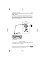
The PVIA1 Wall Plate features a pass-through video connector to conveniently allow for video access from a video source such as an Z•880, S12, S8
or V883 to a connected VIA! Touch Panel.
Connect the RG-59/RG-6 cable from the VIA! In-Wall Touch Panel location
to the rear panel coaxial connector of the PVIA1 Wall Plate. Connect the
video cable from the central equipment location to the front panel composite
connector of the PVIA1 In-Wall. Use VIA!TOOLS setup software to assign
video switching as required by the system’s architecture. See VIA!TOOLS for
detailed programming instructions.
From Source
To VIA! Touch Panel
Figure 3-10: Pass-Through Video Connection
Page 24
© 2008 ELAN Home Systems • All Rights Reserved
ELAN HOME SYST E M S
PVIA1
IR Out - Front
The IR OUT port is a 3.5mm mono mini jack connection typically used to
control a device that is part of the main IR system in a stand-alone application. IR is routed to an emitter as shown in Figure 3-10 or an IR distribution
block connected to the IR OUT and sent to the source components with IR
emitters as shown in Figure 3-11.
PVIA1
PWR1
ELAN
IR Emitter
A/V Receiver
Figure 3-11: IR OUT
NOTE: When IR is connected to the front of the PVIA1 Wall Plate, IR
pass-through on the rear is disabled
© 2008 ELAN Home Systems • All Rights Reserved
Page 25
PVIA1
ELAN HOME SYST E M S
IR Out - Front
Connecting Block
VIA! 40/70/100EM
3.5mm mono cable
w/ end removed
PWR1
To Back
of PVIA1
PVIA1
Digital Music Server
IR Emitter
Satellite
PWR2
IR Emitter
DVD
Amplified IR
Connection Block
IR Emitter
Figure 3-12: Front Panel IR Out to Connecting Block
Page 26
© 2008 ELAN Home Systems • All Rights Reserved
ELAN HOME SYST E M S
PVIA1
IR Out - Rear
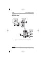
The ELAN IRD4 is the perfect companion to the PVIA1 Wall Plate in a
stand-alone application. The IRD4 is a single input, four output Amplified IR
Connection Block designed to provide a convenient way of interconnecting
IR control of source components to the PVIA1Wall Plate. This unit includes
a robust, wide-bandwidth amplifier with reverse voltage protection so that it
has the ability to drive both Mini-Emitters and High-Output Emitters reliably.
Connect IR OUT and GND from the rear panel of the PVIA1Wall Plate to CAT5 cabling and terminate it to the IRD4 IR IN and GND. Connect IR Emitters
from their Output ports and place on the source component IR Receive windows. Power up the IRD4 and with VIA!Tools programming downloaded to
the VIA! Touch Panel the sources are ready to be controlled.
PWR1
PVIA1 Rear
.
VIA! 40/70/100EM
+16V
GND
+16V
GND
.
V485+
V485IR
ST/SNS
Z485+
SIR
Z485-
PWR2
Amplified IR
Connection Block
ELAN
IR Emitters
Sources
Figure 3-13: Rear Panel IR OUT to IRD4 Connecting Block
© 2008 ELAN Home Systems • All Rights Reserved
Page 27
PVIA1
ELAN HOME SYST E M S
POWER CONNECTION
Use an ELAN PWR1 16VDC/1.5 A power supply connected to the 16VDC
PWR1 connector for one VIA! Touch Panel.
VIA! Touch Panels will be powered locally by the power supply that comes
with the PVIA1 Wall Plate when used in a Stand-Alone application. When VIA!
Touch Panels are used in a Multi-Room Systems they may be powered by
the power supply used with the SPP Precision Panel. The SPP has connectivity provided for a PWR1, PWR4, and PWR10 Power Supply.
For complete SPP Applications & Connections refer to the SPP Installation
Manual.
PWR1
Figure 3-14: PVIA1 and PWR1
Page 28
© 2008 ELAN Home Systems • All Rights Reserved
ELAN HOME SYST E M S
PVIA1
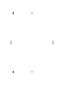
POWER SENSE
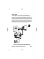
In a stand-alone application the power status of an A/V receiver or cable
box may need to be monitored when using the VIA! Touch Panel. System
ON/Off status feedback will be displayed in the feedback window at the top
of the screen of the Touch Panel. Connect an ELAN PWR9 9 VDC Power
Supply into the 9 VDC connector on the PVIA1 Wall Plate and plug it into the
switched outlet of the source device. The VIA! Touch Panel can then sense
whether source voltage is present or not, and display feedback and execute
macros based on the source power state. Power On and Power Off macros
can be programmed for all Home Theater components using VIA!TOOLS. See
VIA!TOOLS for detailed programming instructions.
VIA! 40/70/100EM
To Back
of PVIA1
Inwall
A/V Receiver
OR
To Switched
Outlet
PVIA1
Inwall
PWR9
Cable Box
Figure 3-15: Power Sense Connection
© 2008 ELAN Home Systems • All Rights Reserved
Page 29
PVIA1
ELAN HOME SYST E M S
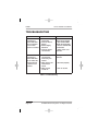
TROUBLESHOOTING
Symptom
Cause
Solution
VIA! Touch Panel 1. No Power Supply
connected to
Connected
PVIA1 Wall Plate
2. Incorrect Power
will not activate/
Supply
turn-on when
3. Power Supply
screen is touched
defective
4. Incorrect power
connections
1. Connect PWR1 or
PVIA1 Power Supply
2. Use PVIA1/PWR1
16VDC Power Supply
3. Test for 16VDC with
a multimeter
4. Verify power connections
VIA! Touch Panel
connected to
PVIA1 Wall Plate
has no video displayed when TV
or Camera icon
touched
1. Verify video connections
1. Video cable not
connected or
incorrectly con
nected
2. Video In/Out connected back
wards
3. Video source
turned off
2. Connect properly
3. Turn on source
Table 4-1: Troubleshooting
Page 30
© 2008 ELAN Home Systems • All Rights Reserved
ELAN HOME SYST E M S
PVIA1
APPENDIX A: SPECIFICATIONS
Specifications
Connections
System Port (RJ-45), Video IN (composite
connector), Video OUT (“F” connector)
Power Terminal, Sense Power Terminal
Wiring Requirements Cat-5 (Data), RG-6 or RG-59 coaxial cable
(Composite Video)
Power
PWR1 16VDC 1.5Amp (included), PWR9
9VDC 100mA (optional)
Unit Dimensions
Length 4.1” Width 1.9” Depth 1.5”
(L 104.14mm W 48.26mm D 38.1mm)
Unit Weight
2.7 oz (0.168 lbs)
Table A-1: Specifications
© 2008 ELAN Home Systems • All Rights Reserved
Page 31
Limited Warranty
ELAN HOME SYSTEMS L.L.C. ("ELAN") warrants the PVIA1 In-Wall to be
free from defects in materials and workmanship for the period of two years (2 years)
from date of purchase. If within the applicable warranty period above purchaser
discovers that such item was not as warranted above and promptly notifies ELAN
in writing, ELAN shall repair or replace the item at thecompany's option.
This warranty shall not apply (a) to equipment not manufactured by ELAN,
(b) to equipment which shall have been installed by other than an ELAN
authorized installer, (c) to installed equipment which is not installed to ELAN's
specifications, (d) to equipment which shall have been repaired or altered by others
than ELAN, (e) to equipment which shall have been subjected to negligence, accident,
or damage by circumstances beyond ELAN's control, including, but not limited to,
lightning, flood, electrical surge, tornado, earthquake, or other catastrophic events
beyond ELAN's control, or to improper operation, maintenance or storage, or to other
than normal use of service. With respect to equipment sold by, but not manufactured
by ELAN, the warranty obligations of ELAN shall in all respects conform to the
warranty actually extended to ELAN by its supplier. The foregoing warranties do not
cover reimbursement for labor, transportation, removal, installation or other expenses
which may be incurred in connection with repair or replacement.
Except as may be expressly provided and authorized in writing by ELAN, ELAN shall
not be subject to any other obligations or liabilities whatsoever with respect to
equipment manufactured by ELAN or services rendered by ELAN.
THE FOREGOING WARRANTIES ARE EXCLUSIVE AND IN LIEU OF ALL OTHER
EXPRESSED AND IMPLIED WARRANTIES EXCEPT WARRANTIES OF TITLE, INCLUDING
BUT NOT LIMITED TO IMPLIED WARRANTIES OF MERCHANTABILITY AND FITNESS
FOR A PARTICULAR PURPOSE.
ATTENTION: TO OUR VALUED CONSUMERS
To ensure that consumers obtain quality pre-sale and after-sale support and service,
ELAN Home Systems products are sold exclusively through authorized dealers.
ELAN products are not sold online. The warranties on ELAN products are NOT VALID
if the products have been purchased from an unauthorized dealer or an online E-tailer.
To determine if your ELAN reseller is authorized, please contact ELAN Home Systems
at (859) 269-7760.v
2428 Palumbo Drive Lexington, KY 40509
www.elanhomesystems.com
P/N 9900639 REV:B