1
IP Link Power Control Interface
IPL T PCS4 and IPL T PCS4i
68-738-07 Rev. A
03 05
Precautions
Safety Instructions • English
This symbol is intended to alert the user of important operating and maintenance
(servicing) instructions in the literature provided with the equipment.
This symbol is intended to alert the user of the presence of uninsulated dangerous
voltage within the product's enclosure that may present a risk of electric shock.
Warning
Power sources • This equipment should be operated only from the power source indicated on the
product. This equipment is intended to be used with a main power system with a grounded
(neutral) conductor. The third (grounding) pin is a safety feature, do not attempt to bypass or
disable it.
Caution
Power disconnection • To remove power from the equipment safely, remove all power cords from
the rear of the equipment, or the desktop power module (if detachable), or from the power
source receptacle (wall plug).
Read Instructions • Read and understand all safety and operating instructions before using the
equipment.
Power cord protection • Power cords should be routed so that they are not likely to be stepped on or
pinched by items placed upon or against them.
Retain Instructions • The safety instructions should be kept for future reference.
Servicing • Refer all servicing to qualified service personnel. There are no user-serviceable parts
inside. To prevent the risk of shock, do not attempt to service this equipment yourself because
opening or removing covers may expose you to dangerous voltage or other hazards.
Follow Warnings • Follow all warnings and instructions marked on the equipment or in the user
information.
Avoid Attachments • Do not use tools or attachments that are not recommended by the equipment
manufacturer because they may be hazardous.
Slots and openings • If the equipment has slots or holes in the enclosure, these are provided to
prevent overheating of sensitive components inside. These openings must never be blocked by
other objects.
Lithium battery • There is a danger of explosion if battery is incorrectly replaced. Replace it only
with the same or equivalent type recommended by the manufacturer. Dispose of used batteries
according to the manufacturer's instructions.
Consignes de Sécurité • Français
Avertissement
Ce symbole sert à avertir l’utilisateur que la documentation fournie avec le matériel
contient des instructions importantes concernant l’exploitation et la maintenance
(réparation).
Alimentations• Ne faire fonctionner ce matériel qu’avec la source d’alimentation indiquée sur
l’appareil. Ce matériel doit être utilisé avec une alimentation principale comportant un fil de
terre (neutre). Le troisième contact (de mise à la terre) constitue un dispositif de sécurité :
n’essayez pas de la contourner ni de la désactiver.
Ce symbole sert à avertir l’utilisateur de la présence dans le boîtier de l’appareil de
tensions dangereuses non isolées posant des risques d’électrocution.
Déconnexion de l’alimentation• Pour mettre le matériel hors tension sans danger, déconnectez tous
les cordons d’alimentation de l’arrière de l’appareil ou du module d’alimentation de bureau (s’il
est amovible) ou encore de la prise secteur.
Attention
Lire les instructions• Prendre connaissance de toutes les consignes de sécurité et d’exploitation avant
d’utiliser le matériel.
Conserver les instructions• Ranger les consignes de sécurité afin de pouvoir les consulter à l’avenir.
Respecter les avertissements • Observer tous les avertissements et consignes marqués sur le matériel ou
présentés dans la documentation utilisateur.
Eviter les pièces de fixation • Ne pas utiliser de pièces de fixation ni d’outils non recommandés par le
fabricant du matériel car cela risquerait de poser certains dangers.
Protection du cordon d’alimentation • Acheminer les cordons d’alimentation de manière à ce que
personne ne risque de marcher dessus et à ce qu’ils ne soient pas écrasés ou pincés par des
objets.
Réparation-maintenance • Faire exécuter toutes les interventions de réparation-maintenance par un
technicien qualifié. Aucun des éléments internes ne peut être réparé par l’utilisateur. Afin
d’éviter tout danger d’électrocution, l’utilisateur ne doit pas essayer de procéder lui-même à ces
opérations car l’ouverture ou le retrait des couvercles risquent de l’exposer à de hautes tensions
et autres dangers.
Fentes et orifices • Si le boîtier de l’appareil comporte des fentes ou des orifices, ceux-ci servent à
empêcher les composants internes sensibles de surchauffer. Ces ouvertures ne doivent jamais
être bloquées par des objets.
Lithium Batterie • Il a danger d'explosion s'll y a remplacment incorrect de la batterie. Remplacer
uniquement avec une batterie du meme type ou d'un ype equivalent recommande par le
constructeur. Mettre au reut les batteries usagees conformement aux instructions du fabricant.
Sicherheitsanleitungen • Deutsch
Vorsicht
Dieses Symbol soll dem Benutzer in der im Lieferumfang enthaltenen
Dokumentation besonders wichtige Hinweise zur Bedienung und Wartung
(Instandhaltung) geben.
Stromquellen • Dieses Gerät sollte nur über die auf dem Produkt angegebene Stromquelle betrieben
werden. Dieses Gerät wurde für eine Verwendung mit einer Hauptstromleitung mit einem
geerdeten (neutralen) Leiter konzipiert. Der dritte Kontakt ist für einen Erdanschluß, und stellt
eine Sicherheitsfunktion dar. Diese sollte nicht umgangen oder außer Betrieb gesetzt werden.
Dieses Symbol soll den Benutzer darauf aufmerksam machen, daß im Inneren des
Gehäuses dieses Produktes gefährliche Spannungen, die nicht isoliert sind und
die einen elektrischen Schock verursachen können, herrschen.
Stromunterbrechung • Um das Gerät auf sichere Weise vom Netz zu trennen, sollten Sie alle
Netzkabel aus der Rückseite des Gerätes, aus der externen Stomversorgung (falls dies möglich
ist) oder aus der Wandsteckdose ziehen.
Achtung
Lesen der Anleitungen • Bevor Sie das Gerät zum ersten Mal verwenden, sollten Sie alle Sicherheits-und
Bedienungsanleitungen genau durchlesen und verstehen.
Aufbewahren der Anleitungen • Die Hinweise zur elektrischen Sicherheit des Produktes sollten Sie
aufbewahren, damit Sie im Bedarfsfall darauf zurückgreifen können.
Befolgen der Warnhinweise • Befolgen Sie alle Warnhinweise und Anleitungen auf dem Gerät oder in
der Benutzerdokumentation.
Keine Zusatzgeräte • Verwenden Sie keine Werkzeuge oder Zusatzgeräte, die nicht ausdrücklich vom
Hersteller empfohlen wurden, da diese eine Gefahrenquelle darstellen können.
Instrucciones de seguridad • Español
Schutz des Netzkabels • Netzkabel sollten stets so verlegt werden, daß sie nicht im Weg liegen und
niemand darauf treten kann oder Objekte darauf- oder unmittelbar dagegengestellt werden
können.
Wartung • Alle Wartungsmaßnahmen sollten nur von qualifiziertem Servicepersonal durchgeführt
werden. Die internen Komponenten des Gerätes sind wartungsfrei. Zur Vermeidung eines
elektrischen Schocks versuchen Sie in keinem Fall, dieses Gerät selbst öffnen, da beim Entfernen
der Abdeckungen die Gefahr eines elektrischen Schlags und/oder andere Gefahren bestehen.
Schlitze und Öffnungen • Wenn das Gerät Schlitze oder Löcher im Gehäuse aufweist, dienen diese
zur Vermeidung einer Überhitzung der empfindlichen Teile im Inneren. Diese Öffnungen dürfen
niemals von anderen Objekten blockiert werden.
Litium-Batterie • Explosionsgefahr, falls die Batterie nicht richtig ersetzt wird. Ersetzen Sie
verbrauchte Batterien nur durch den gleichen oder einen vergleichbaren Batterietyp, der auch
vom Hersteller empfohlen wird. Entsorgen Sie verbrauchte Batterien bitte gemäß den
Herstelleranweisungen.
Advertencia
Este símbolo se utiliza para advertir al usuario sobre instrucciones importantes de
operación y mantenimiento (o cambio de partes) que se desean destacar en el
contenido de la documentación suministrada con los equipos.
Alimentación eléctrica • Este equipo debe conectarse únicamente a la fuente/tipo de alimentación
eléctrica indicada en el mismo. La alimentación eléctrica de este equipo debe provenir de un
sistema de distribución general con conductor neutro a tierra. La tercera pata (puesta a tierra) es
una medida de seguridad, no puentearia ni eliminaria.
Este símbolo se utiliza para advertir al usuario sobre la presencia de elementos con
voltaje peligroso sin protección aislante, que puedan encontrarse dentro de la caja
o alojamiento del producto, y que puedan representar riesgo de electrocución.
Desconexión de alimentación eléctrica • Para desconectar con seguridad la acometida de
alimentación eléctrica al equipo, desenchufar todos los cables de alimentación en el panel trasero
del equipo, o desenchufar el módulo de alimentación (si fuera independiente), o desenchufar el
cable del receptáculo de la pared.
Precaucion
Leer las instrucciones • Leer y analizar todas las instrucciones de operación y seguridad, antes de usar
el equipo.
Conservar las instrucciones • Conservar las instrucciones de seguridad para futura consulta.
Obedecer las advertencias • Todas las advertencias e instrucciones marcadas en el equipo o en la
documentación del usuario, deben ser obedecidas.
Evitar el uso de accesorios • No usar herramientas o accesorios que no sean especificamente
recomendados por el fabricante, ya que podrian implicar riesgos.
Protección del cables de alimentación • Los cables de alimentación eléctrica se deben instalar en
lugares donde no sean pisados ni apretados por objetos que se puedan apoyar sobre ellos.
Reparaciones/mantenimiento • Solicitar siempre los servicios técnicos de personal calificado. En el
interior no hay partes a las que el usuario deba acceder. Para evitar riesgo de electrocución, no
intentar personalmente la reparación/mantenimiento de este equipo, ya que al abrir o extraer las
tapas puede quedar expuesto a voltajes peligrosos u otros riesgos.
Ranuras y aberturas • Si el equipo posee ranuras o orificios en su caja/alojamiento, es para evitar el
sobrecalientamiento de componentes internos sensibles. Estas aberturas nunca se deben obstruir
con otros objetos.
Batería de litio • Existe riesgo de explosión si esta batería se coloca en la posición incorrecta. Cambiar
esta batería únicamente con el mismo tipo (o su equivalente) recomendado por el fabricante.
Desachar las baterías usadas siguiendo las instrucciones del fabricante.
Table of Contents
Chapter 1 • Introduction ...................................................................................................... 1-1
About This Manual ............................................................................................................ 1-2
About the IPL T PCS4 ........................................................................................................ 1-2
Features .............................................................................................................................. 1-2
Connection diagrams ....................................................................................................... 1-3
Chapter 2 • Installation and Rear Panel .................................................................... 2-1
Installation Overview ...................................................................................................... 2-2
Mounting the IPL T PCS4 Interface .......................................................................... 2-2
Tabletop use ...................................................................................................................... 2-2
Rack mounting .................................................................................................................. 2-2
Under-desk mounting ...................................................................................................... 2-3
Connecting the Hardware ............................................................................................. 2-6
Chapter 3 • Front Panel Features and Operation ............................................... 3-1
Front Panel Features ........................................................................................................ 3-2
Setting up the System Using the Front Panel ................................................... 3-3
Setting up power control ................................................................................................ 3-3
Setting power level reference thresholds ...................................................................... 3-3
None and Not Set thresholds .................................................................................... 3-5
Clearing thresholds .................................................................................................... 3-5
Grouping receptacles ........................................................................................................ 3-6
Ungrouping receptacles ............................................................................................ 3-6
Front panel security lockout (executive mode) ............................................................ 3-6
Resetting the Unit ............................................................................................................. 3-6
Chapter 4 • Web Page-Based Setup and Control ................................................ 4-1
Configuring the Hardware ........................................................................................... 4-2
Setting up and configuring the PC using ARP .............................................................. 4-2
Setting up and configuring the PC using a Web browser ........................................... 4-4
Setting up the PC for IP communication ................................................................ 4-4
Configuring the IPL T PCS4 using a Web browser ................................................. 4-7
Using the Embedded Web Pages .............................................................................. 4-8
Viewing the system status ............................................................................................... 4-9
Configuration .................................................................................................................. 4-10
Specifying system settings ...................................................................................... 4-10
IP settings ............................................................................................................ 4-10
Date and time settings ....................................................................................... 4-11
Assigning passwords ................................................................................................ 4-12
Removing passwords ................................................................................................... 4-12
Entering e-mail addresses for alerts ................................................................................ 4-13
Upgrading firmware ......................................................................................................... 4-14
IPL T PCS4 • Table of Contents
i
PRELIMINARY
Rear Panels and Cabling ................................................................................................ 2-4
Table of Contents, cont’d
Managing receptacles .............................................................................................. 4-14
Switching power to receptacles on and off .................................................... 4-15
Grouping receptacles ......................................................................................... 4-15
Monitoring the receptacles and setting the alarm .............................................. 4-16
Monitoring Settings section .............................................................................. 4-16
Alarm Relay Settings section ............................................................................. 4-17
Scheduling power to receptacles ........................................................................... 4-18
Scheduling an individual receptacle ................................................................ 4-18
Scheduling receptacles by day of the week .................................................... 4-19
File Management ............................................................................................................ 4-20
Uploading files to the Web page ........................................................................... 4-21
Adding a directory ................................................................................................... 4-21
Other file management functions ......................................................................... 4-21
Custom Web Pages ............................................................................................ 4-22
PRELIMINARY
Server side includes (SSIs) .............................................................................................. 4-22
Query strings ................................................................................................................... 4-22
Code example ................................................................................................................. 4-23
URL encoding .................................................................................................................. 4-24
Reserved characters .................................................................................................. 4-24
Unsafe characters ..................................................................................................... 4-25
A/V Device Power Control .......................................................................................... 4-26
Custom Web pages ......................................................................................................... 4-26
Accessing and using Telnet (port 23) ............................................................................ 4-26
Troubleshooting ............................................................................................................... 4-27
Power connections ......................................................................................................... 4-27
Network connections ...................................................................................................... 4-27
Global Viewer Software .............................................................................................. 4-28
Chapter 5 • SIS™ Programming and Control ........................................................... 5-1
Host-to-Interface Communications ......................................................................... 5-2
Messages initiated by the IPL T PCS4 ............................................................................. 5-2
Password information ...................................................................................................... 5-2
Error responses .................................................................................................................. 5-2
Error response references ................................................................................................. 5-3
Using the Command/Response Table ...................................................................... 5-3
Symbol definitions ........................................................................................................... 5-5
Command/response table for SIS commands ................................................................ 5-7
Appendix A • Reference Material .................................................................................. A-1
Specifications ..................................................................................................................... A-2
Part Numbers and Accessories ................................................................................. A-3
Included parts .................................................................................................................. A-3
Optional accessories ........................................................................................................ A-3
Glossary ................................................................................................................................. A-4
All trademarks mentioned in this manual are the properties of their respective owners.
ii
IPL T PCS4 • Table of Contents
68-738-01 Rev. A
03 05
IPL T PCS4
1
Chapter One
Introduction
About This Manual
About the IPL T PCS4
Introduction
About This Manual
This manual contains information about the Extron IPL T PCS4/IPL T PCS4i
Ethernet-based Power Control Interface, including explanations of how to install,
configure, and operate it.
About the IPL T PCS4
The Extron IPL T PCS4/IPL T PCS4i IP Link Power Control Interface is an
Ethernet-based power management device that provides the capability to control
power and to schedule and monitor up to four output devices via TCP/IP. The
IPL T PCS4i is an international version, configured for 220 VAC. Unless otherwise
specified, “IPL T PCS4” and “PCS4” refer to both product versions throughout this
manual.
The PCS4 can be used as a stand-alone control device or as one of many nodes in a
distributed control system environment. It lets you remotely power on and off any
attached device and to individually sample and store device power levels. The
PCS4 has its own Web pages, stored in flash memory within the device.
PRELIMINARY
Features
Remote powering on and off of devices — Centralized management features such
as Telnet allow remote powering on and off of projectors, cameras, video
conferencing equipment, switchers, and other audio/video equipment.
Power level monitoring — Four 3-prong power output receptacles sense the
power level delivered. Each receptacle can sample and store power levels for
a device operating in full or standby mode.
Individual power threshold settings — User-defined power thresholds can be set
for each receptacle. Each threshold can be associated with one or more
actions, such as activation of the alarm relay, e-mail notification, etc. When
power exceeds or falls below a stored threshold, the programmed action(s)
are performed.
Power-up sequencing — Power-up sequencing eliminates power surges at startup. When the IPL T PCS4 restarts, the receptacles are powered on
sequentially, separated by a user-configurable delay. (The factory default
delay time is 1 second.) The attached devices are powered up in ascending
order from receptacle 1 to 4.
The IPL T PCS4 powers up only those devices that were previously powered
on when the restart occurred.
Grouping of receptacles — To support dual powered devices by controlling them
simultaneously, two or more receptacles can be grouped together. Grouping
and ungrouping can be done via the front panel, TCP ports using Simple
Instruction Set™ (SIS™) commands, or internal Web pages.
Detection device (alarm relay) — This relay on the rear panel may be connected to
a relay-controllable siren or other detection device, and can be programmed
to react at specified power level thresholds. The alarm relay can be
configured for either normally open or normally closed state, which activates
the attached alarm device when power drops or increases beyond a specified
amount. E-mail messages can be generated based on alarm relay conditions.
Internet communication — The PCS4 uses standard Ethernet and TCP/IP
communication protocols, including ARP (Address Resolution Protocol),
DHCP (dynamic host configuration protocol), TCP/IP (Transmission Control
Protocol/Internet Protocol), Telnet, and HTTP (HyperText Transfer Protocol).
1-2
IPL T PCS4 • Introduction
Embedded Web page serving — The IPL T PCS4 has 900 KB of internal flash
memory for storing user-customizable Web pages and configuration settings.
Nonproprietary programming (HTML and JavaScript™) is available, as well as
other programming methods.
Security — Built-in multilevel security provides user control over access to devices
attached to the PCS4. Appropriate security is provided by password
protection for Administrator and User levels.
Mounting — The PCS4 can be mounted on a tabletop, for which four feet are
provided and can be attached. Optional hardware for mounting the unit
under a desktop or podium or on a rack shelf is not included, but may be
ordered separately.
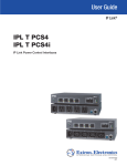
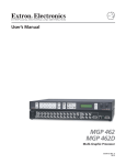
Connection diagrams
PRELIMINARY
The following application diagrams show examples of how devices may be
connected to the IPL T PCS4 in different environments.
LAN
N
LA
AL
Extron
IPL T PCS4
AM
AD
L LO
AR
M
Alarm
AX
10
TA
TO
10A
0V
-12
100
Power Control with
Sensing Capabilities
Cable Box
0V
0-12
10
0 Hz
50/6
Power
(14 gauge)
TV
VCR
DVD
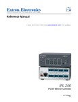
Connection diagram for IPL T PCS4 (14 AWG power cord required in
U. S.)
IPL T PCS4 • Introduction
1-3
Introduction, cont’d
LAN
N
LA
M
AR
AL
Extron
IPL T PCS4
Power Control with
Sensing Capabilities
AD
L LO
TA
TO
0-12
10A
AX
Alarm
0 Hz
50/6
261
310
402
410
301
22 2
anta
Atl ston
Bo nver
Dertfort k
Ha Roc
littlertland
Po
ity
sC
y
nsa
Ka sing a Cit
Lanlahom
Ok Lewis
St.scan
Tulsa
Tu
0
7:00
7:30
9:00
8:30
4:30
6:0
l
anta
Atl ston
Bo nver
Dertfort k
Ha Roc
littlertland
Po
e
261
310
ity
sC
402
nsa g City 410
a
K sin a
n
m
a
301
L laho
is
k
222
O Lew
St.scan
u
T lsa
u
T
e
261
310
402
410
301
222
0
7:00
7:30
9:00
8:30
4:30
6:0
l
tur
par
De
tur
par
De
261
310
402
410
301
22 2
iva
Arr
iva
Arr
PRELIMINARY
AM
10
0V
10
0V
-12
100
0
7:00
7:30
9:00
8:30
4:30
6:0
0
7:00
7:30
9:00
8:30
4:30
6:0
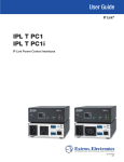
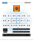
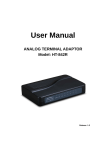
Connection diagram for IPL T PCS4 with airport digital signage
Extron
IPL T PCS4
Power Control w/
Sensing Capabilities
IPL T PCS4
1
2
3
4
F
F
F
F
S
S
S
S
R
SET REFERENCE
STANDBY FULL
IPL T PCS4
1
100
LINK
2
3
4
F
F
F
F
S
S
S
S
R
SET REFERENCE
STANDBY FULL
100
LINK
ACT
ACT
Computer
DVD
VCR
Audio Amplifier
DSS
Cooling Fans
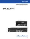
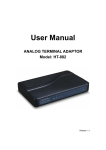
Illustration of an IPL T PCS4 in a home entertainment center
1-4
IPL T PCS4 • Introduction
IPL T PCS4
2
Chapter Two
Installation and Rear Panel
Installation Overview
Mounting the IPL T PCS4 Interface
Rear Panels and Cabling
Connecting the Hardware
Installation and Rear Panel
Installation Overview
PRELIMINARY
To install and set up an IPL T PCS4 interface, follow these steps:
1
Turn all of the equipment off. Make sure that the video sources (DSS, cable
boxes, or other devices), the IPL interface, the output devices (monitors,
VCRs, projectors, etc.), and the controller are all turned off and disconnected
from the power source.
2
Mount the PCS4 interface. See Mounting the IPL T PCS4 Interface, below.
3
Plug the PCS4 power cord into an AC outlet. For the 120 VAC
version, use the supplied 14 AWG IEC power cord (part #27-407-01).
4
Connect an active LAN Ethernet cable to the RJ-45 port on the rear panel to establish
a link to the network.
5
Set up an IP address for the PCS4. (See chapter 4, Web Page-Based Setup and
Control, or chapter 5, SIS™ Programming and Control.)
6
Plug the desired devices into the power receptacles on the PCS4 rear panel.
7
Press the front panel buttons to power on the receptacles.
8
Turn on the output devices.
9
Configure the PCS4 interface through the front panel, Telnet, or the Web pages,
then access the unit using an Internet browser.
Mounting the IPL T PCS4 Interface
The IPL T PCS4 can be set on a table, mounted on a rack shelf, or mounted under
furniture such as a desk, podium, or tabletop.
Tabletop use
Four self-adhesive rubber feet are included with the PCS4. For tabletop use,
attach one foot at each corner of the bottom side of the unit, and place the PCS4
in the desired location.
Rack mounting
Rack mount the interface, if desired, using the included 19" Universal rack shelf
mounting kit.
2-2
IPL T PCS4 • Installation and Rear Panel
Half-rack
false front panel
uses 2 front holes.
IPL
T PC
S4
R
S
1
F
S
2
F
S
3
F
(2) 4-40 x 3/16" screws
Use 2 mounting holes on
opposite corners.
4
S
SE
ST T RE
AN
FE
DB RE
NC
Y
FU E
LL
100
LIN
K
AC
T
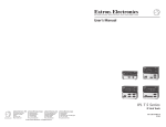
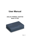
Mounting the IPL T PCS4 on a 1U Universal rack shelf
1.
If rubber feet have been installed on the bottom of the unit, remove them.
2.
Mount the PCS4 on the rack shelf (part #60-190-01), using two 4-40 x 3/16"
screws in opposite (diagonal) corners to secure the unit to the shelf.
3.
Attach a blank panel or other unit(s) to the rack shelf.
4.
Insert the shelf into the rack, aligning the holes in the shelf with those in the
rack.
5.
Secure the shelf to the rack using the supplied machine screws. This shelf
can be mounted in the front or in the rear of the rack.
Under-desk mounting
The PCS4 can also be mounted under furniture, such as a table or podium
surface, using the optional under-desk mounting brackets (part #70-077-01).
1.
If rubber feet were previously
installed on the bottom of the
unit, remove them.
2.
Attach the mounting brackets to
the unit with the provided
machine screws.
3.
Insert #8 wood screws into the
four pilot holes. Tighten each
screw into the mounting surface
until slightly less than ¼" of the
screw protrudes.
N
LA
RM
ALA
AX
AD
L LO
AM
10
TA
TO
10A
0V
-24
200
0V
0-24
20
4.
Align the mounting screws with
the slots in the brackets, and
place the PCS4 against the surface with the screws through the bracket
slots.
5.
Slide the unit slightly forward or back, then tighten all four screws to secure
it in place.
50/
60
Hz
IPL T PCS4 • Installation and Rear Panel
2-3
PRELIMINARY
F
Installation and Rear Panel, cont’d
Rear Panels and Cabling
6
100-120V
1
10A
2
3
4
S/N XXXXXXXXX E0000 0408
00-05-A6-XX-XX-XX
5
LAN
ALARM
100-120V
50/60 Hz
TOTAL LOAD 10A MAX
1
3
2
4
IPL T PCS4 rear panel (120 VAC)
PRELIMINARY
6
200-240V
10A
1
2
3
4
S/N XXXXXXXXX E0000 0408
00-05-A6-XX-XX-XX
5
LAN
ALARM
200-240V
50/60 Hz
TOTAL LOAD 10A MAX
2
1
3
4
IPL T PCS4i rear panel (220 VAC)
1
Power connector — Connect a power cord from the AC power supply to
this male IEC power input receptacle.
For the IPL T PCS4, use the supplied 14 AWG IEC power cord (part
#27-407-01).
2
Output receptacles — Connect power cords from up to four devices to these
three-prong female Edison (IPL T PCS4) or IEC (IPL T PCS4i) power output
receptacles.
3
Alarm relay — Connect a relay-controllable detection device to this singlepole, single-throw relay connector. (Default condition for this relay is
Normally Open.)
4
LAN connector and LEDs — An Ethernet connection can be used on an
ongoing basis to monitor and control the PSC4 (and the devices connected
to it).
RJ-45
Port
RJ-45 port — Plug a patch cable into this RJ-45 female
socket, and connect the other end to a network switch,
hub, router, or PC.
Link
LED
Link LED — This green LED lights to indicate a good
network connection.
LAN
Activity
LED
2-4
Activity LED — This yellow LED blinks to indicate
network activity.
IPL T PCS4 • Installation and Rear Panel
LAN port cabling
• For 10Base-T (10 Mbps) networks, use a Category 3 or better cable.
For 100Base-T networks, use a Category 5 cable.
Use a straight-through cable to connect to a switch, hub, or router.
Use a crossover cable to connect directly to a PC. Wire the connector as
shown in the tables below.
Clip Down
12345678
RJ-45
connector
Straight-through Cable
(for connection to a switch, hub, or router)
End 1
Pin
1
2
3
4
5
6
7
8
12345678
Wire Color
white-orange
orange
white-green
blue
white-blue
green
white-brown
brown
End 2
Pin
1
2
3
4
5
6
7
8
Wire Color
white-orange
orange
white-green
blue
white-blue
green
white-brown
brown
PRELIMINARY
•
•
•
Crossover Cable
(for direct connection to a PC)
Twisted
Pairs
7&8
1&2 3&6 4&5
End 1
Pin
1
2
3
4
5
6
7
8
Wire Color
white-orange
orange
white-green
blue
white-blue
green
white-brown
brown
End 2
Pin
1
2
3
4
5
6
7
8
Wire Color
white-green
green
white-orange
blue
white-blue
orange
white-brown
brown
RJ-45 connector wiring
Configuring the LAN port
You need to configure the LAN port before using it. You can configure the
settings via either SIS commands or the embedded Web pages. See
chapter 4, Web Page-based Setup and Control, or chapter 5, SIS™ Programming
and Control, for details.
LAN port factory defaults:
•
•
•
•
•
Link speed and duplex: Auto Detect
Unit IP address: 192.168.254.254
Subnet Mask: 255.255.0.0
Gateway IP address: 0.0.0.0
DHCP: Off
5
UID # label — Contains the unique User ID number (MAC address) of the
unit (for example, 00-05-A6-00-00-01). On the PCS4, the MAC address is on
a label in the upper-right corner of the rear panel.
6
Serial number label — Contains the serial number of your PCS4 unit.
IPL T PCS4 • Installation and Rear Panel
2-5
Installation and Rear Panel, cont’d
Connecting the Hardware
Connect the cables to the rear panel as follows:
1.
Plug the Ethernet cable from your network into the LAN port on the rear
panel.
2.
Plug the IPL T PCS4 power cord into a wall outlet. All front panel LEDs
flash on briefly; only the power and Ethernet LEDs remain lit. (No
receptacle lights should remain lit.)
A label covers the power receptacle on the IPL T PCS4 (U.S. version),
reminding you that you must use the supplied 14 AWG power cord for the
PCS4 to function properly. Remove this label before connecting the power
cord to the unit.
3.
Plug the power cord of each device to be monitored into one of the
receptacles on the back panel of the PCS4.
4.
If desired, connect a relay-controllable siren or other detection device to the
Alarm relay on the rear panel.
PRELIMINARY
The alarm relay cannot be set up from the front panel. You must use either
SIS commands or the Web pages to configure it. See Monitoring the
receptacles and setting the alarm in chapter 4, or Alarm relay
functions in the SIS commands table in chapter 5.
2-6
IPL T PCS4 • Installation and Rear Panel
IPL T PCS4
3
Chapter Three
Front Panel Features and Operation
Front Panel Features
Setting up the System Using the Front Panel
Resetting the Unit
Front Panel Features and Operation
The PCS4 can be set up and operated by using:
•
•
The front panel controls
A computer or other device using an Ethernet connection and IP protocol
(Telnet or a Web browser)
Some settings can be adjusted only through a host computer using Extron’s
Simple Instruction Set™ (SIS™) via Telnet, or using the PCS4’s embedded Web
pages. For details on setup and control via Ethernet, see chapters 4 and 5.
Front Panel Features
7
6
6
7
6
7
IPL T PCS4
1
PRELIMINARY
1
2
6
7
4
3
F
F
F
F
S
S
S
S
SET REFERENCE
FULL
STANDBY
100
LINK
ACT
R
3
2
5
4
IPL T PCS4/PCS4i front panel
1
Power LED (green) — When this green LED is lit, the PCS4/PCS4i
interface is receiving power and is running.
When the unit is being reset, this LED blinks the appropriate number of
times to indicate the reset mode it has entered.
2
Reset button (recessed) — Use the tip of a Phillips screwdriver or an
Extron Tweeker to press this recessed button to reset the unit in one of four
Reset modes. See Resetting the Unit, later in this chapter, for details on reset
modes and on using this multiple function Reset button.
3
Power control buttons 1-4 — Press these buttons to switch power on and
off to the output receptacle with the corresponding number on the rear
panel. These buttons are also used, along with the Set Reference buttons
( 4 ), to set the Full and Standby power thresholds.
4
Set Reference (Power threshold) buttons — Press these buttons to set the
indicator LEDs for each receptacle to indicate whether the attached devices
is operating at Full or Standby power level.
5
LAN status LEDs — These three LEDs show the status of the Ethernet
connection as follows:
100 (green) — When lit, indicates a 100 Mbs connection speed.
Otherwise, the connection speed is 10 Mbs.
Link (green) — Indicates that the interface has an active network
connection.
Act (yellow) — (Activity) Blinks while data is being sent or received.
6
3-2
Power LED (red) — (One for each receptacle) Indicates that power is being
supplied to the attached device.
IPL T PCS4 • Front Panel Features and Operations
7
Power Management (threshold) LEDs — (Set of two for each receptacle)
After the power thresholds have been set, these LEDs indicate the status of
the attached device as follows:
F (green) — Indicates that power is at or above the Full reference
threshold.
S (yellow) — Indicates that power is at or above the Standby reference
threshold, and below the Full threshold.
Setting Up the System Using the Front Panel
The following system setup procedures can be performed using the front panel,
the embedded Web pages, or the SIS commands.
This section discusses the front panel procedures. For information on using the
Web to set up, see chapter 4. For the equivalent SIS commands, see chapter 5.
To set up control of power to the devices plugged into the
PCS4 receptacles, do the following for each device:
1.
2.
1
On the PCS4 front panel, press and release the
power control button for the receptacle into which
the device is plugged.
F
The red Power LED at the right of the button lights
and remains lit while the receptacle is powered on.
It is unlit when the receptacle is powered off.
S
Power (red) LED
Power on the device, using its own power switch.
Setting power level reference thresholds
You can set the PCS4 to notify you when the power level of a connected device
drops from Full to Standby or to None. For each device, you can use front panel
controls to set the reference threshold (Full or Standby) at which a notification is
triggered.
Until a threshold is set for a receptacle the first time, the status displayed for the
receptacle on the Web page or given in response to SIS™ queries is Not Set. Once
a threshold has been set, the receptacle’s status defaults to None if all thresholds
are cleared. (See None threshold, later in this chapter, for further information.)
There are two common types of power for electronic devices: soft and hard.
•
Soft power devices normally have three power states: On, Standby, and
Off. Such devices include projectors, DVD players, and VCRs.
Example: On soft power devices, the Standby mode allows the unit to be
powered to its Full power mode via RS-232 commands or a remote.
Pressing a PCS4 receptacle button to Off when the receptacle is connected
to a device that supports Standby power causes the device to power off.
•
Hard power devices normally have two power states: on and off. These
devices include Extron switchers and interfaces.
Example: On Extron switchers, there is no power button or Standby
condition, and the unit’s power can be set only to On and Off from the
PCS4 front panel. Therefore, when the power is on, it is at Full power, and
can be set for Full reference threshold.
IPL T PCS4 • Front Panel Features and Operations
3-3
PRELIMINARY
Setting up power control
Front Panel Features and Operation, cont’d
The Full and Standby reference thresholds must be configured with the device
attached to the PCS4 receptacle. The thresholds must be set in the correct order,
with Full being set first. Follow these steps to set the threshold for each device,
using the front panel. (These thresholds also can be configured using the Web
pages or SIS commands. Refer to chapters 4 and 5, respectively.)
The Full threshold must be set first. If Standby is set first, the Standby
reference setting is removed by the setting of the Full reference threshold.
1.
Connect a device to a power output receptacle on the IPL T PCS4. Make a
note of the receptacle number to which you connected it (1-4).
2.
Press the corresponding front panel button to activate the receptacle. Check
to ensure that the receptacle’s red Power LED is lit.
To set the Full power threshold:
3.
Power on the attached device.
4.
Press and hold the Full button on the PCS4 front panel.
PRELIMINARY
SET REFERENCE
FULL
STANDBY
5.
While holding the Full button, press and release the button for the
receptacle into which the device is plugged. Both the green F (Full) LED
and the yellow S (Standby) LED for the selected receptacle blink twice.
Only the green Full LED remains lit.
1
Green
Full
LED
F
S
Receptacle
Button
6.
Release the Full button. The Full threshold for the receptacle is now set.
To set the Standby power threshold:
7.
Power off the attached device.
8.
Press and hold the Standby button.
SET REFERENCE
FULL
STANDBY
3-4
IPL T PCS4 • Front Panel Features and Operation
9.
While holding down the Standby button, press and release the receptacle
button for the same device for which you set the Full threshold. The yellow
Standby LED for the selected receptacle blinks twice and remains lit.
1
F
Yellow
Standby
LED
S
Receptacle
10.
Release the Standby button.
11.
Repeat steps 1 through 9 for any other receptacles to which you have
connected devices to be controlled through the PCS4.
These threshold settings are preserved if the PCS4’s AC power is recycled or if
power is removed from an attached device. For example:
•
If the receptacle is set to Full and the power level drops below the stored
threshold, the receptacle’s F (Full) LED shuts off, and the S (Standby) LED
lights.
•
If the receptacle is set to Standby and the power level drops below the
stored Standby threshold, the S LED shuts off.
•
If the receptacle is set to Standby and the power level exceeds the stored
Standby threshold, the F LED lights.
•
To indicate that the configuration has been saved, both the yellow Standby
LED and the green Full LED light and remain lit when those thresholds are
selected.
None and Not Set thresholds
When a Full and/or Standby reference threshold has been set for a receptacle at
some time, and neither threshold is detected, a threshold status of None appears
on the Web page or can be the response to SIS™ queries. None also appears if the
receptacle is powered off. The None threshold is a state that is detected; it cannot
be set manually.
If a receptacle has never been set to a Full or Standby reference threshold, its
threshold status is shown as Not Set on the Web page and in response to SIS
queries. Not Set is the default setting for reference thresholds.
Clearing thresholds
To remove the reference threshold settings from any receptacle:
1.
Shut off power to the receptacle that you want to clear by pressing its button
on the front panel. The red LED to the right of the button shuts off.
2.
Press and hold the Standby or Full button while pressing and releasing the
receptacle button. All three receptacle LEDs flash twice, indicating that the
settings have been cleared.
3.
Release the Standby or Full button that you were holding.
If desired, you can now turn power for the receptacle on again by pressing
the receptacle’s button.
IPL T PCS4 • Front Panel Features and Operation
3-5
PRELIMINARY
Settings that are made via the front panel for power output receptacles and
reference thresholds take approximately two minutes to be stored in memory.
If you recycle power too soon after settings have been made, the settings will
be lost.
Front Panel Features and Operation, cont’d
Grouping receptacles
Two or more power receptacles can be grouped so that both their connected
devices can be controlled simultaneously. To group receptacles using the front
panel, follow these steps for each receptacle to be grouped.
1.
Place the receptacle in Configuration mode by pressing and holding its
receptacle button for two seconds. The green power LED ( 1 ) flashes
continually, indicating that the unit is in Configuration mode.
2.
Press each receptacle button repeatedly to cycle through the available group
selections, indicated by the LEDs beside the button, until you arrive at the
setting you want for the receptacle:
PRELIMINARY
3.
•
No LEDs lit — No groups (The receptacle will not be part of any
grouping.)
•
Yellow S LED lit — Group 1
•
Green F LED lit — Group 2
•
Red LED lit — Group 3
Press either the Standby or the Full button to exit Configuration mode.
Ungrouping receptacles
To remove a receptacle from a grouping, follow these steps:
1.
Place the receptacle in Configuration mode by pressing and holding its
button for two seconds, until the green power LED ( 1 ) flashes continually.
2.
Press the receptacle button repeatedly until none of its LEDs are lit
(indicating no groups).
3.
Press the Standby or Full button to exit Configuration mode.
Front panel security lockout (executive mode)
When the PCS4 is in executive mode, it does not accept commands from the front
panel. If any button is pressed while the unit is in executive mode, the Power
LED flashes three times, indicating that input from the front panel is not being
accepted.
To enter or exit executive mode, press and hold the Standby and Full buttons
simultaneously for 2 seconds. The Power LED flashes 3 times to indicate that the
mode has been switched.
If power to the PCS4 is recycled while the unit is in executive mode, the
PCS4 remains in executive mode.
Resetting the Unit
There are four ways to reset the PCS4 unit (called modes 1, 3, 4, and 5 for the sake
of comparison with other Extron IPL products). Reset the unit by pressing the
Reset button on the front panel (see Front Panel Features in chapter 3 for the button
location). This button is recessed; it can be accessed with a pointed stylus,
ballpoint pen, or an Extron Tweeker (a small screwdriver provided with the unit).
CAUTION
3-6
The reset modes described on the following pages break all TCP/IP
connections by closing all sockets to the unit.
IPL T PCS4 • Front Panel Features and Operation
IPL
T
PC
S
4
R
F
S
1
F
S
2
F
3
S
F
4
S
SE
ST T RE
AN FE
DB RE
NC
Y
FU E
LL
Recessed Reset Button
10
0
LINK
AC
T
Reset button
Review the reset modes carefully. Use of the wrong reset mode may
result in unintended loss of flash memory programming or a unit
reboot.
If the Reset button is continually held in, the LEDs pulse (blink) every three
seconds, and the PCS4 is put in a different mode, corresponding to the
underscored notes in modes 3 through 5. The mode 5 LED blinks three
times, the third blink indicating that it is the last mode. The following
modes are separate functions, not a progression from mode 1 to mode 5.
Mode 1
Activation — Hold in the Reset button while applying power to the unit.
Result — Returns the unit to the default base firmware that was shipped with
the PCS4 from the factory. Event scripting does not start when the unit is
powered on in this mode.
Purpose and notes — Use mode 1 to remove a version of firmware if
incompatibility issues arise. All user files and settings are maintained.
User Web pages may not work correctly if you are using an earlier firmware
version.
After a mode 1 reset, the factory-installed firmware version remains in effect
only until the unit is powered off. After a power cycle, the PCS4 returns to
the firmware that was installed prior to the mode 1 reset.
Mode 2
Mode 2 is not applicable to this product.
Mode 3
Activation — Hold the Reset button in until the Power LED blinks once (about
three seconds). Release it, then immediately press it again briefly (for less
than one second).
Nothing happens if the brief press does not occur within one second.
Result — Turns events on or off, depending on their current state. During
resetting, the reset LED flashes two times if events are starting and three
times if events are stopping.
Purpose and notes — This mode is used for troubleshooting.
IPL T PCS4 • Front Panel Features and Operation
3-7
PRELIMINARY
CAUTION
Front Panel Features and Operation, cont’d
Mode 4
Activation — Hold the Reset button in until the Power LED blinks twice (about
six seconds). Release it, then immediately press it again briefly (for less
than one second). The Power LED blinks four times in quick succession,
confirming a mode 4 reset.
Nothing happens if the brief press does not occur within one second.
Result — Reset mode 4 does the following:
•
Enables ARP program capability.
•
Sets IP back to factory IP settings.
•
Sets Subnet back to factory default.
•
Sets Gateway back to factory default.
•
Sets port mapping back to factory default.
•
Turns DHCP off.
•
Turns events off.
PRELIMINARY
Purpose and notes — Mode 4 enables you to set IP address information using
ARP and the MAC address.
Mode 5
Activation — Hold in the Reset button until the Power LED blinks three times
(about nine seconds). Release it, then immediately press it again briefly (for
less than one second). The power LED blinks four times in quick
succession, confirming a mode 5 reset.
Nothing happens if the brief press does not occur within one second.
Result — Performs a complete reset to factory defaults (except for the firmware).
Purpose and notes — Mode 5 is useful if you want to start over with control
software configuration and to replace events.
3-8
IPL T PCS4 • Front Panel Features and Operation
IPL T PCS4
4
Chapter Four
Web Page-Based Setup and Control
Configuring the Hardware
Using the Embedded Web Pages
Custom Web Pages
A/V Device Power Control
Troubleshooting
Global Viewer Software
Web Page-Based Setup and Control
The IPL T PCS4 must be configured before use, or it cannot control other devices.
In addition to using the buttons on the PCS4 front panel, you can configure and
control the PCS4 via any computer attached to a LAN.
• The default Web pages embedded within the PCS4 provide a means to perform
some setup, adjustment, and control via a Web browser from any type of
network-enabled computer.
• An alternative way to control and configure the PCS4 from your computer is by
using Simple Instruction Set (SIS) commands via Telnet or a Web browser. SIS
commands are discussed in detail in chapter 5.
Configuring the Hardware
To function together, both the PC and the PCS4 must be configured correctly. The
PC must be network-capable with the proper protocols, and the PCS4 must be set
up so it can be connected to a LAN (local area network). Please note that some
settings can be configured only via Internet protocol.
PRELIMINARY
For your PC to communicate with the PCS4, it must have a Windows-based
(Windows NT, 2000, XP, or higher) operating system and be equipped with an
network interface card. To allow your PC to work with Extron’s Ethernetcontrolled products, the TCP/IP protocol must be installed and properly
configured.
Setting up and configuring the PC using ARP
The Address Resolution Protocol (ARP) command provides a quick way to set up
an IP address for the PCS4, using your PC. The ARP commands tell your
computer to associate the PCS4’s Media Access Control (MAC) address with an
IP address that you assign. After entering the ARP command, you enter a ping
command to access the PCS4, at its new address to confirm the address has been
successfully changed.
1.
Obtain a valid IP address for your PCS4 from your network administrator.
2.
Obtain the PCS4’s MAC address (UID#) from the label on its rear panel.
The MAC address should have the following format:
00-05-A6-nn-nn-nn
3.
If the PCS4 has never been configured and is still set for factory defaults,
skip to step 4. If not, perform a mode 4 system reset to restore the factory-set
values. (See Resetting the Unit, in chapter 3, for the resetting procedure.)
CAUTION
4.
The PCS4 must be configured with the factory default
address (192.168.254.254) before you execute the ARP
command, as described below.
At the PC, access the MS-DOS command prompt, then enter arp -s, the
desired new IP address for the PCS4, a space, and finally the PCS4’s MAC
address (taken from the label on the rear panel). For example:
arp -s 10.13.170.15 00-05-A6-00-0A-90
4-2
IP
IPL T PCS4 • Web Page-Based Setup and Control
After the arp -s command is issued, the PCS4 changes to
the new address and starts responding to ping requests, as
described in the next step.
5.
To verify that the new address has been set, execute a ping command by
entering “ping,” followed by the new IP address, at the command prompt.
Ping is a utility or diagnostic tool that tests network connections. It is used
to determine if the host has an operating connection and is able to exchange
information with another host.
Example:
ping 10.13.170.15
The response should be the PCS4’s new IP address, as shown below.
Screen showing the Ping command
You can reconnect using either Telnet or a Web browser to verify that the
update was successful.
6.
After verifying that the IP address change was successful, issue the arp -d
command at the DOS prompt to remove the address from the ARP table. For
example:
arp -d 10.13.170.15
IPL T PCS4 • Web Page-Based Setup and Control
4-3
PRELIMINARY
ARP-S command screen
Web Page-Based Setup and Control, cont’d
Setting up and configuring the PC using a Web browser
To set up the PCS4 using a Web browser, you must temporarily configure the PC
to communicate with the interface. Then you can change the PCS4’s default
settings (IP address, subnet mask, and [optionally] administrator name and
password) in order to use the unit on an intranet (LAN) or on the Internet
(WAN). After you have set up the PCS4 for network communication, you can
reset the PC to its original network configuration.
IPL T PCS4’s LAN port defaults:
•
•
•
•
•
PCS4’s IP address: 192.168.254.254
Gateway’s IP address: 0.0.0.0
Subnet mask: 255.255.0.0
DHCP: Off
Link speed and duplex level: Auto detected
PRELIMINARY
If you use an existing Ethernet LAN intranet, your network administrator can
provide you with a unique IP address for the PCS4 or confirm whether you need
to set up the PCS4 for DHCP (Dynamic Host Configuration protocol) to have an
address assigned automatically when you sign on.
Setting up the PC for IP communication
Follow these steps to set up communication between your PC and the PCS4. (The
illustrations in this section show screens from Windows 2000. Your screens may
appear slightly different.)
1.
Open the Network Connections page as follows:
Windows 2000:
a.
Locate and right-click My Network
Places on the Windows desktop.
b.
Select Properties.
or
a.
Click the Start menu, and select Settings (if necessary).
b.
From the Start menu, select Control Panel.
c.
On the Control Panel window, double-click Network Connections, then
Dial-up Connections (if necessary).
Windows XP:
4-4
a.
From the Start menu, select My Network Places.
b.
From the Network Tasks side-bar menu, select View Network
connections.
IPL T PCS4 • Web Page-Based Setup and Control
Right-click Local Area Connection, then select Properties.
3.
Select Internet Protocol (TCP/IP), and click the Properties button. If Internet
Protocol (TCP/IP) is not on the list, it must be added (installed). Refer to the
Windows user’s manual or the Windows online help system for
information on how to install the TCP/IP protocol.
4.
Write down your PC’s current IP address and subnet mask below. You will
need to restore these settings to the PC later.
PRELIMINARY
2.
If Obtain an IP address automatically has been selected, make a note of
that. If not, write down the following:
IP address:
__________________________
Subnet mask:
__________________________
5.
Change the PC’s IP address temporarily so that it can communicate
with the PCS4.
a.
Select the “Use the following IP address:” radio button.
IPL T PCS4 • Web Page-Based Setup and Control
4-5
Web Page-Based Setup and Control, cont’d
b.
Enter the following values as shown below:
IP address: 192.168.254.253
Subnet mask: 255.255.0.0
Default gateway: Blank or 0.0.0.0
PRELIMINARY
(The temporary IP address differs from the PSC4’s factory default by
one digit.)
6.
c.
Click OK to save the changes, and exit the network setup.
d.
Reboot the PC, if required, for the changes to become effective.
Plug one end of a Category 5 network/Ethernet crossover cable into the
Ethernet (LAN) connector on the PCS4 rear panel. (Refer to chapter 2,
Installation and Rear Panel, for information on the RJ-45 LAN connector
wiring.) Plug the other end of the Ethernet cable into the Ethernet port on
the PC.
If you are using a network hub or switch between the PC and the PCS4, use a
straight-through Category 5 cable instead of a crossover cable.
7.
Set up the PCS4’s IP address. See Configuring the IPL T PCS4 using a Web
browser, in the next section, for the procedure.
Once the PCS4 has been reconfigured, an Ethernet (intranet or Internet)
connection can subsequently be used to configure or control it.
Both your computer and the PCS4 must be connected to the same LAN.
Alternatively, you may use a crossover Ethernet cable to connect the
interface directly to your computer’s Ethernet card.
8.
4-6
After setting the PCS4’s IP address, restore the PC’s previous IP
configuration by following steps 1, 2, 3, and 5 but using the PC’s original IP
address settings that you wrote down in step 4.
IPL T PCS4 • Web Page-Based Setup and Control
Configuring the IPL T PCS4 using a Web browser
The default Web pages that are preloaded on the PCS4 are compatible with
popular Web browsers such as Internet Explorer (version 5.5 or higher).
The following instructions assume that you have already configured the
Windows-based PC, connected it to the PCS4’s LAN port, and powered on
the interface.
Obtain a valid IP address, subnet mask, and gateway address for the
PCS4 from your network administrator.
2.
Launch a Web browser (such as Internet Explorer) on the connected PC (for
which you set up the network configuration earlier), and enter the PCS4’s
default address, http://192.168.254.254, in the address box. The PCS4’s
default Web page is displayed.
3.
Select the Configuration tab, then select System Settings from the side bar
menu on the left of the screen. A configuration System Settings Web page
appears. A typical settings screen is shown below.
PRELIMINARY
1.
Example of a default system settings page
4.
IP, gateway, and subnet mask addresses follow standard naming and
numbering conventions and protocol (xxx.xxx.xxx.xxx). The IP network
administrator should provide the addresses to be used with this interface.
Enter the new IP address assigned for the PCS4, the corresponding subnet
mask, and gateway address, then click Submit.
The PSC4 takes approximately two minutes to store the new settings. Once
the interface’s IP address is changed, your PC loses communication with
the PCS4, and a screen appears, indicating that the page cannot be
displayed.
5.
Close the browser.
6.
After changing the PCS4’s IP settings, change your PC’s TCP/IP settings
back to their original configuration, and reboot if necessary. You are now
able to access the PCS4’s web pages to configure the front panel.
IPL T PCS4 • Web Page-Based Setup and Control
4-7
Web Page-Based Setup and Control, cont’d
Using the Embedded Web Pages
The PCS4 features an embedded Web server, which includes factory set Web
pages. These pages can be replaced with user-designed files, but the default Web
pages provide many basic features for monitoring, configuring, and controlling
the PCS4 via a Web browser. This section provides an overview of the embedded
Web pages.
To access the embedded Web pages:
1.
Launch a Web browser (e.g., Internet Explorer) on your connected PC.
2.
On the browser’s Address line, enter the PCS4’s IP address. If a password
has been set, the Enter Network Password dialog box opens.
PRELIMINARY
If no password has been set, the PCS4 Web page opens, displaying the
System Status tab. (Skip steps 3 and 4.)
3.
In the User Name field on the password window, enter text of your choice,
or leave the User Name blank.
4.
Enter the administrator password in the Password field, and click OK. The
PCS4 Web page is displayed.
Passwords must contain 4 to 12 alphanumeric characters. Symbols and
spaces are not allowed, and the passwords are case sensitive.
Administrators have access to all of the Web pages and are able to make
changes to settings. Users can access only the System Status page.
4-8
IPL T PCS4 • Web Page-Based Setup and Control
Viewing the system status
The System Status Web page on the Status tab provides information on the
current settings. Changes must be made via the Configuration Web pages or SIS
programming commands (see chapter 5, SIS Programming and Control). Personnel
who have user access can view this page but cannot access the Configuration or
File Management tab pages to make changes.
PRELIMINARY
The following figure shows an IPL T PCS4 System Status web page.
System Status Web page
The System Status page displays information in the following categories:
•
System Description: Includes product model, a brief description, part number,
and firmware version, plus the current date and time.
•
IP Settings: Displays the unit’s name, IP address, MAC address, and all other
current IP settings.
•
AC Receptacles: For each receptacle, shows whether the receptacle is turned
on or off; the current power level threshold setting (Full, Standby, Not Set, or
None); whether the receptacle is part of a group; and the alarm state.
•
Current Schedule: Shows the day of the week and the time that any receptacle
has been scheduled to power on and off.
IPL T PCS4 • Web Page-Based Setup and Control
4-9
Web Page-Based Setup and Control, cont’d
Configuration
There are seven Configuration Web pages, which only administrators can access.
They are listed in the side-bar menu at the left of the Configuration screen. The
following sections discuss the tasks that you can perform on these screens.
Specifying system settings
PRELIMINARY
On the System Settings screen, you can set the date and time, and change the IP
address information for the PCS4. To change the available system settings,
follow these steps:
System Settings screen on the Configuration tab
1.
On the Configuration tab, select System Settings from the side-bar menu at
the left edge of the screen. The System Settings screen appears, displaying
either the factory default information for your PCS4, or the settings
submitted most recently.
2.
Enter your new information in the IP Settings section or select the date and
time from the menus in the Date/Time Settings section.
IP settings
The following settings are available in the IP Settings section:
•
Unit Name: The default is the product name followed by the last six
digits of the MAC address. You can give the unit a new name (such as
“LigntsOn&Off” or “BoardroomA-PCS4”) consisting of up to 24
alphanumeric characters including the hyphen (-).
The first character must be an alpha character, and the last
character cannot be a hyphen. The unit name is not case-sensitive.
4-10
•
DHCP: DHCP is a communications protocol that assigns addresses
on the local network automatically. Select the On or Off radio button to
enable or disable DHCP.
•
IP Address: You can enter a new network address consisting of four
sets of up to three digits, separated by periods (xxx.xxx.xxx.xxx).
IPL T PCS4 • Web Page-Based Setup and Control
•
Gateway IP Address: A gateway is a device that connects your
network with others that may be using different, incompatible
communications protocols. You can enter your gateway’s address
(obtained from your network administrator), using the same format
that is used for the IP Address. (If there is no gateway, this field
defaults to 0.0.0.0.)
•
Subnet mask: The subnet mask is used to split IP networks into a
series of subgroups (subnets). The mask is a binary pattern that is
matched up with the IP address to turn part of the host ID address
field into a field for subnets. You can enter a new subnet mask
address using the same format that is used for the IP Address.
This section lets you set the date and time on your PCS4 unit. However, the
passage of time is not reflected in the Date and Time fields on the Web page.
The screen continues to display the settings you entered and does not
increment them as time passes. However, the PCS4 itself continues to keep
the correct time internally, enabling you to schedule power on and off for the
receptacles.
•
•
Date: Select month, day, and/or year from the pull-down menus.
•
Zone: From the pull-down menu, select the time zone for the PCS4’s
location (number of hours offset from Greenwich mean time).
•
Daylight Savings: Daylight savings time (DST) is a one-hour offset
that is observed in some countries. You can select a radio button to set
the PCS4 for daylight savings time for the U. S., Europe, or Brazil; or
select Off to disable it.
Time: Select hours, minutes, and/or AM or PM from the pull-down
menus.
The following daylight savings periods are observed:
o
U. S. — Starts the first Sunday in April and ends the last Sunday
in October.
o
Europe — Starts the last Sunday in March and ends the last
Sunday in October.
o
Brazil — Starts the first Sunday in October and ends the third
Sunday in February. (Equatorial Brazil does not observe DST.)
3.
When you have made all the desired changes in one section, click the
Submit button at the bottom of the section. The new IP settings are
displayed at the right of the fields in which you entered them. The new
date and time settings are displayed in the fields in which you entered or
selected them.
4.
Follow steps 2 and 3 to make changes in the other section, if desired.
Clicking Cancel in either section restores the previous settings, if the values you
entered have not been submitted.
IPL T PCS4 • Web Page-Based Setup and Control
4-11
PRELIMINARY
Date and time settings
The following settings are available in the Date/Time Settings section.
Web Page-Based Setup and Control, cont’d
Assigning passwords
The Passwords screen allows you to assign passwords to the Administrator and
User access levels. The Administrator password gives access to all IPL T PCS4
Web pages, enabling the administrator to configure the PCS4.
The User password provides access only to the System Status Web page. If you
are logged in as User, you see only the Status tab with the System Status screen.
You cannot make any configuration changes.
To assign passwords:
1.
On the Configuration tab, select Passwords from the side-bar menu.
2.
Enter the new administrator password in the Administrator Password
field.
PRELIMINARY
Passwords must contain 4 to 12 alphanumeric characters. Symbols and
spaces are not allowed, and the passwords are case sensitive.
3.
In the Re-enter Admin Password field, enter the same password again to
confirm it.
4.
If you want to assign a User password, enter it in the User Password field.
You cannot assign a User password unless an Administrator password has
either been assigned or is being assigned at the same time.
5.
Re-enter the same User password in the Re-enter the User Password field.
Passwords screen with Administrator and User passwords entered
6.
Click Submit to set the password(s).
Removing passwords
To remove a password, follow these steps:
1.
Access the Passwords screen on the Configuration tab.
2.
In the Administrator Password and/or the User Password field, delete the
characters that are there, and press the Spacebar to enter a space.
3.
Repeat step 2 in the Re-enter Admin Password and/or the Re-enter User
Password field.
4.
Click Submit.
Deleting the Administrator password also deletes the User password.
4-12
IPL T PCS4 • Web Page-Based Setup and Control
Entering e-mail addresses for alerts
PRELIMINARY
If you have created scheduled events or monitoring tasks on the PCS4, you can
write an e-mail alert with a message corresponding to that event or task (e.g., a
change in power level for one of the attached devices). The e-mail alert can notify
up to 48 recipients at one time; the Email Alerts screen lets you enter up to 48
e-mail addresses.
E-mail Alerts screen (upper portion)
To edit notification e-mail addresses, follow these steps:
1.
On the side-bar menu on the Configuration tab, click Email Alerts.
2.
On the Email Alerts screen, click the Edit button located to the right of the
Mail IP Address and Domain Name fields. The screen goes into Edit mode,
and the Edit button changes to Save.
3.
Enter your mail server’s IP address and your domain name in the
appropriate fields. (This information is available from your network
administrator.)
4.
Click Save to save the information.
5.
Click the Edit button at the end of the first address row in which you want
to enter a new address or edit the existing one. The Edit button changes to
Save (see the illustration above).
6.
Enter the alert recipient’s e-mail address in the numbered box under Email
Address.
7.
In the File Name column, enter the name (seven characters maximum) of the
file containing the alert message. The message file name must have the
extension .eml.
Due to the seven-character limit for full file names, it is recommended that
you use numeric file names (e.g., 1.eml, 24.eml, etc.). Numeric titles reduce
the characters in the file name and assist in keeping the alert files organized.
However, alphabetic titles are permitted.
IPL T PCS4 • Web Page-Based Setup and Control
4-13
Web Page-Based Setup and Control, cont’d
8.
Click the Save button beside the file name that you entered. The e-mail alert
information is saved on the PCS4, and the Save button becomes Edit again.
9.
Repeat steps 5 through 8 for each e-mail recipient address that you want to
add or edit.
Upgrading firmware
The Firmware Upgrade screen lets you browse to locate and upload a new
version of firmware for your unit. The uploaded file must have the file extension
.S19.
PRELIMINARY
The PCS4’s .S19 file is not the same as the .S19 files of other products and
is not interchangeable with any other product’s firmware upgrade files.
Firmware upgrade screen
To upload a new version of firmware:
1.
On the side-bar menu of the Configuration tab, click Firmware Upgrade.
The Firmware Upgrade screen is displayed, showing the version of
firmware that is currently loaded.
2.
Click Browse to open a Windows file selection window.
3.
On the file selection window, locate the new firmware version file on your
server and double-click it. (Firmware files must have the extension .S19.)
The firmware file name and path are displayed in the Current Firmware
Version field on the Firmware Upgrade screen.
4.
Click Upload. When the firmware upgrade is complete, the Power LED on
the unit blinks three times.
If you attempt to upload a file with an extension other than .S19, the PCS4
recognizes it as invalid and ignores it, reverting to the factory installed
firmware version.
Managing receptacles
On the Switching/Grouping screen, you can switch power on and off to each
individual receptacle, group the receptacles together, and power each group on
and off. You can also view the threshold settings (Full, Standby, None, or Not Set)
indicating the device power level at which the alarm relay will be activated for
each receptacle.
You cannot set the reference thresholds on this screen. This can be done only
from the IPL T PCS4 front panel or via SIS commands. Refer to Setting
power level reference thresholds in chapter 3 or to chapter 5, SIS™
Programming and Control, for information on setting thresholds from the
front panel or via SIS commands.
4-14
IPL T PCS4 • Web Page-Based Setup and Control
Switching/Grouping screen
1.
On the Configuration tab, select Switching/Grouping from the side-bar
menu.
2.
In the Power column, select the On or Off radio button beside the number of
each receptacle that you want to switch. If you want to switch a group of
receptacles, select On or Off for one of the receptacles in that group. (See
Grouping receptacles, below.)
3.
Click Submit to put your changes into effect.
If you turn power on by pressing the receptacle button on the front panel
while this screen is displayed, the screen does not change to reflect your
actions until you click Refresh.
Grouping receptacles
You may want to group two or more receptacles together to ensure that they are
switched on or off at the same time. You can create up to three groups. To group
receptacles, follow these steps:
1.
Locate the number of the first receptacle that you want to group.
2.
In the Group Number column, select the radio button for the group number
(1, 2, or 3) to which you want to assign the receptacle.
3.
Repeat steps 1 and 2 for the rest of the receptacles that you want to group
with the first one.
4.
When you have made all desired grouping selections, click Submit.
After receptacles have been grouped, any power selection that you make for
one of the grouped receptacles is also performed on the others in that group
when you click Submit.
If you do not want to group a receptacle with any others, select None for it.
IPL T PCS4 • Web Page-Based Setup and Control
4-15
PRELIMINARY
Switching power to receptacles on and off
To turn power to receptacles on and off:
Web Page-Based Setup and Control, cont’d
Monitoring the receptacles and setting the alarm
The Monitor screen on the Configuration tab lets you monitor each receptacle for
any change in its power or its reference threshold condition (full or standby
power). You can also configure the alarm relay and set up the alarm to sound
and/or an e-mail notification to be sent out if any condition at a receptacle
changes.
PRELIMINARY
This screen is updated continually. In addition, you can update it by clicking
Refresh. Refresh also removes any settings that have been entered but have not
been submitted, and returns the entire screen to the settings that were saved
previously.
Monitor screen
To set up receptacle monitoring and configure the alarm, follow these steps:
1.
On the side-bar menu on the Configuration tab, click Monitor.
2.
In the Monitoring Settings and/or Alarm Relay Settings section, enter your
selections (described in the following sections).
3.
When you are finished making selections in one section, click the Submit
button at the bottom of the section to implement your changes. (If you want
to undo all the entries you made in this section, click Cancel instead of
Submit.)
Monitoring Settings section
In this section, you can specify the following settings for each receptacle by
making selections in the row beside its number.
4-16
•
Enable: Select this check box to initiate monitoring of the receptacle. If this
box is not selected, all the other fields in the row are grayed out and you
cannot enter settings for the receptacle.
•
Condition: From the pull-down menu, select the condition that will be
monitored. Options include receptacle or device power on or off; Full,
Standby, or None power threshold levels; or any change in conditions at
the receptacle.
•
Send E-mail: Enter an e-mail address to which the PCS4 will send a
preconfigured notification if the selected condition is met.
IPL T PCS4 • Web Page-Based Setup and Control
•
Activate Relay: Select this check box to specify that the relay alarm will
sound (activate) if the selected condition is met. If this box is not selected,
any changes you make to the alarm relay settings are ignored.
•
Alarm status: Indicates whether or not the PCS4 has detected the
condition that is being monitored. This column can display the following:
o
inactive — Appears when the receptacle is not being monitored, or the
condition being monitored has not been detected.
o
active — Appears in red when the PCS4 detects the condition for
which the receptacle is being monitored. In addition, a Silence button
appears at the right of the status, and a pulsing red light icon appears
by the number of the receptacle for which the condition was met.
o
silenced — Appears in red when you click the Silence button to clear
the monitored condition. In addition, the pulsing red light icon is
replaced by an exclamation point icon (!).
Alarm Relay Settings section
In this section, you can configure the alarm relay by making selections in the
following fields.
The Activate Relay check box must be selected for these settings to take effect.
•
Initial State: Select Open or Closed from the pull-down menu for the initial
state of the alarm relay. (The default is Open.)
•
Action: From the pull-down menu, select the way in which the alarm will
respond when activated. This depends on the Initial State setting of the
relay (see the table below).
•
•
o
Activate — Steady tone if the relay’s initial state is set to On. If the
initial state is set to Off, this option turns the alarm relay off.
o
Pulse — Alarm turns on for the selected duration of seconds, then
stops.
o
Oscillate — The alarm is on for a specified duration of seconds, then
off for a specified period, producing an intermittent tone.
Duration (seconds): From the pull-down menus, select the length (in
seconds) of the alarm tone action selected in the Action field (Pulse or
Oscillate only).
o
For Pulse, you can set the length of the single tone (On field).
o
For Oscillate, you can set the length of the repeating tone (On field) and
the amount of time between tones (Off field).
Cancel Alarm when: From one of the following menus, select the
condition that will stop the alarm tone.
o
Condition Changes — Select the type of change in conditions that will
make the alarm stop sounding. (Selecting Manual specifies that the
tone will not stop without user intervention via the front panel, the
powered device, or SIS commands.)
o
Duration — Select the number of minutes the alarm will continue to
sound before it shuts off.
IPL T PCS4 • Web Page-Based Setup and Control
4-17
PRELIMINARY
To reset the alarm status, deselect and reselect the Enable check box for the
receptacle being monitored, then click Submit. The Alarm Status column
displays “inactive” again and the ! icon is removed.
Web Page-Based Setup and Control, cont’d
Scheduling power to receptacles
The Schedule screen on the Configuration tab lets you schedule when power to
the receptacles is turned on and off. You can schedule receptacles individually
to turn on or off at desired times, or you can select a group of receptacles to turn
on or off at one time. Clicking the Clear Schedule button deletes all schedules.
You may want to set up your schedule for a week at a time, or a day at a time.
PRELIMINARY
To access the Schedule screen, click Schedule on the side-bar menu on the
Configuration tab.
Schedule screen showing field for individual receptacle scheduling
Scheduling an individual receptacle
To schedule power on and off to an individual receptacle, follow these steps:
4-18
1.
Locate the number of the receptacle that you want to schedule, and click On
or Off in the Power column beside it. A Set Schedule For field opens,
displaying the selected receptacle number, the power selection (On or Off),
and menus from which to select the hour, minute, and AM/PM. (The
illustration above shows the Schedule screen with a Set Schedule For field
displayed for receptacle 2, with power ON at 1:00 p.m. Monday and
Thursday.)
2.
From the pull-down menus, select the time (hour and minutes and AM or
PM) at which you want power turned on or off to the selected receptacle.
3.
Select the check box(es) for the day(s) of the week you want the receptacle to
be turned on and/or off at the time you specified.
4.
When finished, click Set to save your settings for that receptacle.
5.
Repeat steps 1 through 4 for the remaining power schedule setting for the
receptacle you just scheduled, or for other receptacles that you want to
schedule.
IPL T PCS4 • Web Page-Based Setup and Control
Scheduling receptacles by day of the week
There are two types of schedules that you can set up for one day of the week. The
two setup procedures are described below.
All receptacles on and off
Follow this procedure to select both the powering on and powering off times for
all desired receptacles on one day of the week.
Click on a day of the week at the top of a column in the scheduling table.
Two Set Schedule For fields open, one for Power ON and one for Power OFF.
These fields contain pull-down menus for selecting powering on and off
times, as well as check boxes for selecting the receptacles you want to
schedule.
PRELIMINARY
1.
Schedule screen showing fields for daily receptacle scheduling
2.
In either the Power ON or Power OFF section, select the hours, minutes, and
AM/PM from the menus; and select the check box(es) for the receptacle(s)
that you want to schedule.
3.
In the section in which you made your selections, click Set to enter your
choices. The field in which you made your selections closes.
4.
If desired, repeat steps 2 and 3 in the other Set Schedule For field.
If you do not want to make selections in the remaining Set Schedule For
field, click Refresh to close the field.
If you do not click Set before making any selections in the other field, the
second field selections override those that you entered in the first.
5.
Repeat steps 1 through 4 for any additional days that you want to schedule.
IPL T PCS4 • Web Page-Based Setup and Control
4-19
Web Page-Based Setup and Control, cont’d
One receptacle, power on or off
Follow this procedure if you want to schedule only powering on or powering off
of one receptacle on one day.
1.
In the scheduling table, click on the time displayed or the “-” symbol in the
cell beside On or Off for the receptacle number that you want to set, in the
column for the day you want to schedule. A Set Schedule For field appears.
PRELIMINARY
In the following illustration, the red circle indicates the cell that was
selected: receptacle 2, powering off, on Tuesday.
Set Schedule For field to set powering off for a single receptacle
2.
In the Set Schedule For field, select the hour, minute(s), and AM or PM from
the pull-down menus.
3.
Click Set to enter your settings. The time that you entered appears in the
cell that you selected on the Scheduling table.
File Management
The File Management Web page allows you to upload and delete files from the
server. File names must contain valid alphanumeric characters and
underscores; spaces and special characters (symbols) are not allowed. Only
personnel with administrator access can view these pages and make changes.
File Management screen with two files uploaded
4-20
IPL T PCS4 • Web Page-Based Setup and Control
Uploading files to the Web page
The IPL T PCS4 has approximately 900 Kbytes of space for user files to be
uploaded. The Bytes Left field shows how much space remains for uploading
files.
To upload files, follow these steps:
1.
Select the File Management tab on the IPL T PCS4 Web page.
2.
On the File Management screen, click Browse to open a Windows file
selection window.
3.
On the file selection window, locate and select a file to upload. (Only one
file at a time can be selected.) The file name and directory path appear in
the Browse field on the File Management screen.
4.
Click Upload File While the file is uploading, the button label changes to
Uploading... .
Adding a directory
To add a directory or folder to the IPL T PCS4’s file system, follow these steps:
1.
Enter a name for the directory in the Dir: field, following the slash (/).
2.
Click Add Dir.
3.
With the directory name displayed, perform the Uploading files procedure
described in the previous section to add a file to the directory. The directory
name appears at the top of the Files column, preceded by a slash.
If no files are added to the new directory, it is deleted.
To add more files to the directory, click the directory name to open it, then use the
Uploading files procedure. To exit the directory, click (root).
Other file management functions
On the File Management screen, you can also do the following:
• Open and view an uploaded file by clicking on its name.
• Delete an uploaded file by clicking on the Delete button beside it.
• Delete all uploaded files and directories by clicking the Delete All button.
IPL T PCS4 • Web Page-Based Setup and Control
4-21
PRELIMINARY
When the uploading is complete, the uploaded file name appears in the Files list
with a time stamp showing GMT time, and the button returns to its original state.
(Files are listed separately under headings of their extensions.)
Web Page-Based Setup and Control, cont’d
Custom Web Pages
On the PCS4, custom Web pages are supported. You can determine the layout
and appearance of the pages displayed on your screen. Server side includes (SSIs)
enable you to obtain information from the unit and display the information on
Web pages. Query strings allow you to send information and commands to the
unit to change its configuration or provide you with feedback. (See Query strings,
later in this chapter.)
Server side includes (SSIs)
Server sides includes are a type of HTML comment that directs the Web server to
dynamically generate data for a Web page whenever it is requested. SSIs
typically use Extron’s Simple Instruction Set™ (SIS™) commands to communicate
with the products or attached control devices. Using SSIs, you can design and
display custom pages, with PCS4 information provided by the SIS commands.
The basic format for an Extron SSI is:
<!—#echo var=”x”—>
where x is the SIS command to be executed.
PRELIMINARY
When a Web page is requested, the Web server removes the SSI and replaces it
with the answer to the SIS command within quotes.
Server Side Include Using
the Host SIS command
SIS Command
<!--#echo var="
*type with no spaces
N
"-->
SIS command
to be processed
by the IP Link
Example of SSI command
In the figure above, the “N” command is used to request the PCS4’s part number.
Query strings
A query string is the portion of a URL that appears after the question mark. The
query string contains parameters or instructions for the Web server to execute.
The basic format for a query string within a link is:
<a href=”index.html?cmd=x”>Receptacle 1</a>
where x is the SIS command to be executed.
When a link is accessed on a Web page, the URL is passed to the Web server to
tell it which Web page to return to the browser. The portion of the URL after the
question mark is the query string, which contains the SIS command that the
IPL T PCS4 will remove and execute.
Like SSI formatted commands, query strings can use any valid SIS command.
4-22
IPL T PCS4 • Web Page-Based Setup and Control
The query string in the figure below turns off DHCP on the IP Link device.
URL with a Query String Using an SIS Command
SIS Command
<a href="index.html
?
Starts
query string.
HTML Code
for a Link
cmd=
W1*1PC|
">
Receptacle on
</a>
Tells web server
that SIS
command follows.
SIS Command
To Be Processed
by the IP Link
HTML Code
for a Link
Linked Text
Closes
link.
*Enter with no spaces.
Example of a query string command
Code example
PRELIMINARY
The following figure shows a practical use for both SSIs and query strings. In
this example, the HTML source code contains three SSI commands.
<html>
<head><title>Example 1</title></head>
<h2 b>HTML Example #1</h2 b>
<body>
The following lines demonstrate how to read status from the IPLink Product:
IPLink Product Name: <b><!--#echo var="1I"--></b>
<br>
SSI
IPLink Product Description: <b><!--#echo var="2I"--></b>
commands
<br>
IPLink Product Part Number: <b><!--#echo var="N"--></b>
</body>
</html>
Web page HTML source code document showing SSIs
The SSI commands in the previous figure request the product name, product
description and product part number of an IP Link device.
<html>
<head><title>Example 1</title></head>
<h2 b>HTML Example #1</h2 b>
<body>
The following lines demonstrate how to read status from the IPLink Product:
IPLink Product Name: <b>IPL T PCS4</b>
<br>
IPLink Product Description: <b>Four Switched 110v AC Receptacles with
Current Threshold Sensing</b>
<br>
IPLink Product Part Number: <b>60-544-07</b>
</body>
</html>
Resulting HTML source code served by an IP Link Web server
Notice, in the figure above, that the commands executed by the PCS4 in response
to SSI references have been replied to, and were implemented when the Web page
was served to the browser.
IPL T PCS4 • Web Page-Based Setup and Control
4-23
Web Page-Based Setup and Control, cont’d
Browser view of previous HTML source code
URL encoding
PRELIMINARY
URL (Universal Resource Locator) encoding is the method of using ASCII
hexadecimal characters to display specific characters in a URL. It is used for
several reasons. On some operating systems, certain characters are unsafe or not
available, and others are reserved by the HTML or URL specification. URL
encoding is used to insure compatibility and functionality with most Internet
browsers. As a general rule, use the hexadecimal encoding method shown below
when these characters appear in your URLs.
The following types of characters do not require encoding in a URL:
alphanumerics
0-9 a-z A-Z
special characters
$__.+!*(),
reserved characters
;/?:@=&
When used for their reserved purposes, these
characters do not require encoding within a URL.
Characters that do not require encoding
Reserved characters
Reserved characters should not be encoded when they appear in their
conventional meaning in a URL. For example, do not encode the slash (/) when
using it as part of the URL syntax. Only encode unsafe characters (defined in the
table in the next section) in your URLs.
The following table lists reserved characters.
4-24
IPL T PCS4 • Web Page-Based Setup and Control
Characters
Hex
Dec
$
Dollar
24
36
&
Ampersand
26
38
+
Plus
2B
43
,
Comma
2C
44
/
Forward slash / virgule
2F
47
:
Colon
3A
58
;
Semi-colon
3B
59
=
Equal
3D
61
?
Question mark
3F
63
@
“At” symbol
40
64
Unsafe characters
URLs use some characters for “special use” in defining their syntax and these
characters should be encoded. For various reasons, these characters may
possibly be misunderstood within a URL. The following table lists unsafe
characters.
Hex
Dec
Space
20
32
""
<
>
Quotation marks
“Less Than” symbol
“Greater Than” symbol
22
3C
3E
34
60
62
#
Pound
23
35
%
Percent
25
37
7B
7D
7C
5C
5E
7E
5B
5D
60
123
125
124
92
94
126
91
93
96
Characters
Miscellaneous characters
{
}
|
\
^
~
[
]
`
Left curly brace
Right curly brace
Vertical bar / pipe
Backslash
Caret
Tilde
Left square bracket
Right square bracket
Grave accent
Unsafe characters
IPL T PCS4 • Web Page-Based Setup and Control
4-25
PRELIMINARY
Reserved characters
Web Page-Based Setup and Control, cont’d
A/V Device Power Control
Power control of A/V devices may be accomplished once the PCS4 interface has
been connected and configured. These include Web pages and Telnet.
Custom Web pages
These pages can either be modified versions of the existing Web pages, or new
Web pages developed in the field.
Web page development can be done with a Web site development tool such as
FrontPage or Dreamweaver. Custom Web pages can be loaded using the Web
server File Manager (see Managing Files, earlier in this chapter).
Accessing and using Telnet (port 23)
Telnet, short for Telecommunications Network, provides a way for you to connect
to a computer or server (in this case, the PCS4 interface) on a network. Once
connected via Telnet, you can send ASCII serial commands (see the Command/
response table for SIS commands in chapter 5) to configure and monitor the PCS4
settings.
PRELIMINARY
1.
Click Start, then Run, then enter Telnet and click OK. The Telnet program
starts (see the figure below).
Telnet command prompt
2.
At the command prompt, enter open.
3.
At the < to > prompt, enter the IP address of the PCS4 unit. (The default IP
address is 192.168.254.254. If the address was changed in the setup or
configuration process, use the new address.) Telnet defaults to port 23.
Connecting to the IP address
4-26
IPL T PCS4 • Web Page-Based Setup and Control
4.
If passwords were set up for the connected system, you are prompted to log
in as an administrator or a user. Otherwise the system responds with a
carriage return and line feed (<cr/lf>).
5.
Once you are connected, you can enter SIS commands as desired.
6.
When you are finished entering commands to the interface, enter Ctrl + ] at
the command prompt to exit Telnet.
Troubleshooting
Turn on the equipment in the following order:
1.
The PCS4 power control interface
2.
The power receptacles on the PCS4
3.
The connected output device(s)
If the output A/V device cannot be powered on, check the following:
1.
Make sure that the receptacle for each device is receiving power. The
receptacle’s red Power LED lights if the receptacle is powered on. If
necessary, press the receptacle button to apply power.
2.
Ensure that all devices are plugged in properly to the rear panel of the PCS4
and switched on if applicable.
Network connections
1.
Check the network connections and make adjustments as needed. The Link
LED is solid green if a network connection is detected. The yellow ACT
LED blinks if there is activity on the network. If these LEDs are not lit,
either the cable is faulty or not plugged in, or the wrong type of cable is
being used (refer to Connecting the Hardware, in chapter 2).
2.
At the DOS command prompt, try to ping the unit by entering ping and the
IP address assigned to your PCS4. (See Setting up and configuring the PC
using ARP, in chapter 4.) If the PCS4 is connected, you receive the following
response to your Ping command:
Successful Ping command response
IPL T PCS4 • Web Page-Based Setup and Control
4-27
PRELIMINARY
Power connections
Web Page-Based Setup and Control, cont’d
If the connection was not made, the following response appears:
Response to an unsuccessful ping command
PRELIMINARY
If you get a response indicating that the ping was unsuccessful, do the
following:
3.
a.
Make sure your unit is using the appropriate subnet mask (check with
your system administrator).
b.
Make sure your PC does not have a software firewall program which
might block the IP address of the unit.
If contact is established with the unit, but the unit’s Web pages cannot be
accessed by your Web browser, verify (in the Options or Preferences menu)
that your Web browser is configured for direct network connection and not
set up to use a proxy server.
If you are still experiencing problems, call the Extron S3 Sales & Technical
Support Hotline if needed.
Global Viewer Software
The Global Viewer Configurator (GVC) software is an alternative to using the
Web pages to configure and monitor the PCS4. GVC is a free asset management
software that enables flexible, centralized, Web-based power management for
A/V systems. Using Global Viewer software, administrators can view the
immediate status and power levels of all connected devices, schedule powering
on and off of the devices, and configure the alarm triggers.
You can download the latest version of Global Viewer (1.6) from the Extron Web
site as follows:
4-28
1.
Select the Products tab on the Extron Web site home page.
2.
From the side bar menu at the left of the screen, select Software, then Control
Software.
3.
On the Control Software page, click Global Viewer Configurator.
4.
On the Download Center screen, fill in the requested information and click
Download GVConfigInstallv16.exe. Follow the instructions on the
subsequent screens to complete the download.
IPL T PCS4 • Web Page-Based Setup and Control
IPL T PCS4
5
Chapter Five
SIS™ Programming and Control
Host-to-interface Communications
Using the Command/Response Tables
SIS™ Programming and Control
The IPL T PCS4 can be remotely set up and controlled via a host computer or
other device (such as a switch, hub, or router) attached to the rear panel LAN
port.
The PCS4 must be configured before use. As shipped, the PCS4 works as a
standalone interface, but cannot control any other devices until it is configured.
The PCS4 can be set up and controlled by using the front panel (see chapter 3),
the Web pages (see chapter 4), or Extron’s Simple Instruction Set™ (SIS™)
commands (discussed in this chapter). Both the Web pages and the SIS methods
are accessed via Ethernet LAN connection.
LAN port defaults:
• IPL T PCS4 IP address: 192.168.254.254
• Gateway IP address: 0.0.0.0
• Subnet mask: 255.255.0.0
• DHCP: Off
Host-to-interface Communications
PRELIMINARY
SIS commands consist of one or more characters per field. No special characters
are required to begin or end a command sequence. When the PCS4 determines that
a command is valid, it executes the command and sends a response to the host
device. All responses from the interface to the host end with a carriage return and
a line feed (CR/LF = ), which signals the end of the response character string. (A
string is one or more characters.)
Messages initiated by the IPL T PCS4
When a local event such as a front panel selection or adjustment takes place, the
PCS4 responds by sending a message to the host. No response is required from
the host. The following PCS4-initiated messages are sent (underlined):
©
Copyright 2004, Extron Electronics, IPL T PCS4 and IPL T PCS4i,, Vx.xx
Thu, 20 Feb 2004 17:51:04
The PCS4 sends the boot and copyright messages when it first powers on and is
connected via Telnet or TCP/IP. Vx.xx is the firmware version number. The
current date and time are displayed. If you are using a Telnet connection, the
copyright message, date, and time are followed by a password prompt.
Password information
The “ Password:” prompt is displayed only if there is a password defined in
the unit. It requires a password (administrator level or user level) followed by a
carriage return. The prompt is repeated if the correct password is not entered.
If the correct password is entered, the unit responds with “ Login
Administrator ” or “ Login User ,” depending on the password entered. If
the passwords are the same for both administrator and user, the unit defaults to
administrator privileges.
Error responses
When the PCS4 receives a valid SIS command, it executes the command and
sends a response to the host device. If the PCS4 is unable to execute the
command because the command is invalid or it contains invalid parameters, it
returns an error response to the host.
5-2
IPL T PCS4 • SIS™ Programming and Control
The error response codes and their descriptions are as follows:
E12 – Invalid port number
E13 – Invalid value (the number is out of range/too large)
E14 – Not valid for this configuration
E17 – System timed out
E22 – Busy
E24 – Privilege violation
E25 – Device is not present
E26 – Maximum number of connections has been exceeded
E27 – Invalid event number
E28 – Bad filename or file not found
Error response references
14
= commands that give an E14 (invalid command for this configuration)
response if sent to an IPL product whose power configuration does not
support the command.
24
= commands that give an E24 (privilege violation) response if you are not
logged in at the administrator level.
27
= commands that may yield an E27 (invalid event number) response.
28
= cmmands that may give an E28 (file not found) response.
Using the Command/Response Table
The PCS4 can be controlled via either a Telnet (port 23) connection or a Web
browser (port 80) connection. The ASCII and URL commands listed in the tables
starting on page 5-7 perform the same functions, but they are encoded differently
to accomodate the requirements of each port (Telnet or browser).
The ASCII to hexadecimal (HEX) conversion table below is for use with the
command/response tables.
ASCII to HEX Conversion Table
•
ASCII to Hex conversion table
The command/response tables list valid ASCII (for Telnet) command codes, the
corresponding URL (universal resource locator) encoded (for Web browsers)
command codes, the interface’s responses to the host, and a description of the
command’s function or the results of executing the command.
•
Upper- and lower-case characters may be used interchangeably in the
command field unless otherwise specified.
•
Commands may be sent back-to-back without spaces (for example,
2!65V1Z).
IPL T PCS4 • SIS™ Programming and Control
5-3
PRELIMINARY
The following superscripted numbers are used within the command descriptions
on the following pages to identify commands that may respond as shown:
SIS™ Programming and Control, cont’d
•
•
Numbers can be entered as 1, 2, or 3 digits (e.g., 8V = 08V = 008V).
There are a few differences in how to enter the commands, depending on
whether you are using Telnet or a Web browser.
o
When using these commands through a Web browser, you can use the
URL reference to shorten the examples. “URL” refers to the full
address of the control interface and Web page reference, including all
path information (e.g., http://192.168.100.10/myform.htm).
o
To send any of the commands using a Web browser you must prefix
them with the full URL followed by ?cmd=.
o
For control via a Web browser, all non-alphanumeric characters must
be represented as the hexadecimal equivalent, %xx, where xx
represents the two-character hex byte. For example, a comma (,) would
be represented as %2C. Characters such as %, +, and the space
character must be encoded as hex bytes, or they will be misinterpreted
by the interface.
o
Some characters differ depending on the method you use to send the
commands:
PRELIMINARY
Telnet
Escape (hex 1B)
Carriage return (hex 0D)
Web browser
W (must not be hex encoded)
Pipe character (| ) (must not be hex
encoded)
With Telnet you can use either an “Escape” command or a “W” command,
and the carriage return or the pipe character. With the Web browser, you are
required to use a “W” command and the pipe character.
In either method, {Data} = Data that will be directed to a specified port and
must be hex encoded if non-alphanumeric.
5-4
IPL T PCS4 • SIS™ Programming and Control
Symbol definitions
CR/LF (carriage return + line feed) (hex 0D 0A)
=
Soft carriage return (no line feed, hex 0D)
(For Web browser commands, use the |
[pipe] character instead of the soft return.)
|
=
Pipe (vertical bar) character
•
=
Space
=
The 24 superscript indicates commands that give
an E24 (privilege violation) message if you
are not logged in at the administrator level.
24
Esc
=
X1 =
X3
X5
X6
X9
X10
=
=
=
=
=
X16
=
X18
=
Hardware (MAC) address (xx-xx-xx-xx-xx-xx).
X19
=
Subnet mask (xxx.xxx.xxx.xxx). Leading zeros
are optional in setting values in each of four
fields, and they are suppressed in returned
values.
X22
=
For Verbose/Response Mode:
0 = clear/none
1 = verbose mode
2 = tagged responses for queries
3 = verbose mode and tagged responses for
queries
Default = 0
Escape key (hex 1B)
(For Web browsers, use W instead of Esc. )
Power receptacle ( 1-4)
Greenwich Mean Time (GMT) offset value
(-12.00 to +14.00) represents the time
difference in hours and minutes (+/-hh:mm)
relative to Greenwich, England. The plus
sign and leading zero are optional. For
example, 5:30 = +05:30.
On/off status
0 = off/disable
1 = on/enable
Dirty memory status
1 = RAM needs to be saved to flash memory.
0 = RAM has been saved to flash (OK to
power off or reset).
If tagged responses is enabled, all read commands
return the constant string plus the data, like
setting the value does.
Example:
Command: Esc CN
Response: Ipn • X12
X33
=
Password (minimum length = 4 characters;
maximum length = 12 characters. No special
characters are allowed.
X34
=
Daylight saving time (DST) is a 1-hour offset to
reflect the time during which clocks are set
one hour or more ahead of local standard
time, to provide more daylight at the end of
the working day. Supported for the U. S. and
parts of Brazil and Europe.
Current threshold sense
0 = clear/none
1 = standby
2 = full
(Full threshold must be set before standby.)
Example: Time in California is GMT -8:00
from April to October and GMT -7:00 from
November to March.
Group number
0 = none
1 = yellow
2 = green
3 = red
DST should be turned off in Hawaii,
American Samoa, Guam, Puerto Rico, the
Virgin Islands, the eastern time zone portion
of the state of Indiana, and the state of
Arizona (excluding the Navajo Nation).
(The exponent designates the port number.
The color relates to setting groups via the
front panel.)
X11
X12
Version (typically listed to two decimal places,
e.g., x.xx)
X41
=
=
Unit name. The name of the PCS4 is a text
string of up to 24 characters drawn from the
alphabet (A-Z), digits (0-9), and minus sign/
hyphen (-). No blank or space characters are
permitted as part of a name. No distinction
is made between upper and lower case.
X45
=
E-mail event number (1 - 64)
X46
=
E-mail recipient’s address (e.g., [email protected])
for the person to whom messages will be
sent.
X47
=
Name (numeral) of e-mail file to be sent; e.g.,
1.eml, 2.eml, ... 64.eml.
X49
=
Default name: a combination of the model name
and the last 3 pairs of the interface’s MAC
address (e.g., IPL-T-PCS4-00-02-3D).
X52
=
Connection’s security level
11 = user
12 = administrator
X63
=
Pulse time in 20 ms per count. If this parameter
is missing or = 0, then pulse length = default
(25 = 500 ms). 35565 ms = max. pulse time.
=
Local date and time format
Set format (MM/DD/YY-HH:MM:SS).
Example: 11/18/03-10:54:00.
Read format (day of week, day month year
HH:MM:SS).
Example: Tue, 18 Nov 2004 18:19:33.
X14
X15
0 = off/ignore
1 = on
=
The first character must be a letter. The last
character must not be a minus sign/hyphen.
X13
Power-up delay between ports in 1/3 second
increments. 1-255 permitted. (Default is 3,
which equals 1 second.)
=
=
IP address (xxx.xxx.xxx.xxx). Leading zeros in
each of four fields are optional in setting
values, and they are suppressed in returned
values.
Reading password. Responds with four asterisks
(****) in place of the password, if a password
exists. Responds with an empty space if no
password exists.
E-mail domain name, e.g., extron.com.
IPL T PCS4 • SIS™ Programming and Control
5-5
PRELIMINARY
=
SIS™ Programming and Control, cont’d
X67
PRELIMINARY
X69
=
=
Threshold settings for all ports
0 = None
1 = Full
2 = both (Full and Standby thresholds)
(Ethernet only) Number of seconds before
timeout on IP connections (min = 1,
max = 6500, and default = 30 = 300 seconds).
If no data is received during the timeout
period, the Ethernet connection is closed.
Each step is 10 seconds. The response is
returned with leading zeros.
X70
= The number (as an optional parameter) that is
inserted into the e-mail message if the .eml
file has an embedded Esc
command
(with no parameters).
X701
= Condition that is monitored
0 = Receptacle off
1 = Receptacle on
2 = Reference: None
3 = Reference: Standby
4 = Reference: Full
5 = Any change
X702
= Use alarm relay
0 = no/disable
1 = yes/enable
X703
= E-mail to use 61-64
X704
= Enable/disable monitoring
0 = disable monitoring
1 = enable monitoring
2 = enable with e-mail
X705
= Alarm status
0 = inactive
1 = active
2 = silenced
X706
= Clear value
0 = condition no longer met
1 = clear with output off
2 = clear with output on
3 = clear with no threshold
4 = clear with standby threshold
5 = clear with full threshold
6 = clear with any change
7 = manual
X707
= Relay polarity
0 = normally open
1 = normally closed
X708
= Time to hold alarm active before canceling
0 = never times out
1-7 = 1 to 7 minutes
X709
= On timed value
X710
= Off timed value
X711
= Day of the week
0-15 (in 250 ms)
0-15 (in 250 ms)
1 = Sunday
2 = Monday
3 = Tuesday
4 = Wednesday
5 = Thursday
6 = Friday
7 = Saturday
X712
= Time in minutes (0-1440)
0 = 00:00 a.m. (midnight)
5-6
IPL T PCS4 • SIS™ Programming and Control
1440 = clear schedule
Example: 1439 = 11:59
Use the following formula (in 24-hour time
format):
(Hour * 60) + minutes = time in minutes
IPL T PCS4 • SIS™ Programming and Control
5-7
X1
X1
X10
Esc
Esc
Esc
Esc
Esc
1X
0X
X
View threshold settings for all ports
Set Executive mode on
Set Executive mode off
View Executive mode
X10
2
X10
X1
TH
X1
*1 TH
* 0 TH
X1
Esc
View scheduling
Turn alarm relay ON
Turn alarm relay OFF
View alarm relay state
Pulse relay
Toggle relay
X711
X711
*
*
1 * 1O
X1 * 0O
1O
1 * 3 * X63 O
1 * 2O
X1
Esc
Alarm relay functions
X703
GP
SA
*
*
X5
X5
X712
SS
*
MA
3
X10
4
X1
X1
X1
X1
X1
%2A
SA|
%2A
X704
X701
SA|
%2A
%2A
X703
SA|
X1
X1
%2A X711
%2A
X5
SS|
%2A X711 %2A X5 %2A X712 SS|
1%2A1O |
X1 %2A0O |
1O |
1%2A3%2A X63 O |
1%2A2O |
W
W
W X706 %2A X707 %2A X708 %2 X709 %2A X710
WMA |
W
W
W
X
W TH|
1X
0X
W
W
X702
GP|
X9
X10
X1
X1
1
X16
X1
X1
2
X10
3
2
X10
X10
X10
4
*
X702
*
X703
*
X704
*
X705
*
*
*
*
*
*
Cpn 1• Rly 1
Cpn 1• Rly 1
X5
X708
X707
X711
X707
X706
X712
*
*
X710
X709
X710
or Cpn 1• Rly 0
or Cpn 1• Rly 0
*
*
*
X709
X708
X1 * X701 * X702 * X703 * X704 * X705
X701
Cpn 1• Rly 1
Cpn 1 • Rly 0
X5
4
3
X1 * X701 * X702 * X703 * X704 * X705
X1
X712
Sst
X706
Arl
Ast
X1 *
Ast
X5
Exe1
Exe0
X9 1, X9 2, X9 3, X9 4
X16
X10
X1
1
Pdt
X10
X10
• Ppc 1
• Ppc 0
Pgp0000
Pgp
Ptc
X10
Pts
2
%2A 0 TH|
X10
X5
Cpn
Cpn
%2A 1 TH|
1
%2A1PC |
%2A0PC |
PC|
PS|
Ptf
X10
X1
X1
X1
X1
Response
W0000GP |
WGP |
W X16 DT |
W DT |
W X1 %2A 2 TH|
W
W
W
W
W
URL Encoded (Web)
PRELIMINARY
SS
MA
4
X706 * X707 * X708 * X709 * X710
X1
Esc
* X701 * X702 *
SA
* X704 SA
X10
Esc
X1
Esc
3
Esc
X1
Esc
Set scheduling
Power receptacle scheduling
Set Alarm mode
View Alarm mode
Set alarm conditions
View alarm conditions
Monitoring enable or disable
Power receptacle monitoring and alarm functions
Esc
Clear individual threshold
Esc
Esc
Esc
Esc
1
0000GP
GP
X16 DT
DT
X1 * 2 TH
X1
Esc
Esc
X1
Esc
Set individual standby threshold
Ungroup receptacles
View receptacles grouping
Set power up delay
View power up delay
Set individual full threshold
Turn receptacle power on
Turn receptacle power off
View receptacle power status
Query receptacle current status
Group receptacles
* 1PC
* 0PC
PC
PS
ASCII (Telnet)
Power receptacle control / current sense
Command
Command/response table for SIS commands
5-8
Esc
1 * X69 TC
1TC
Esc
TC
0*
Esc
X69
ASCII (Telnet)
firmware version
firmware information
bootstrap version
factory firmware version
updated firmware version
Q
1Q
2Q
3Q
4Q
Q
1Q
2Q
3Q
4Q
W 0 %2A X69 TC|
Esc 0TC
W1%2A X69 TC|
W1TC |
URL Encoded (Web)
X69
X11 (kernel version - model
description - date time)
X11
X11
X11
X11
X69
Pti 0 * X69
W0TC |
Pti1 * X69
Response
IPL T PCS4 • SIS™ Programming and Control
4I
Request user memory usage
Read response from last URL cmd
Web browser-specific commands
View e-mail events (mailbox)
Send e-mail events (file named in mailbox)24
Send e-mail (using different file)24
Configure e-mail events (mailbox)24
Example:
X45 , X70 , X47
Esc
UB
X45
Esc
X45
Esc
CR
SM
SM
X45 , X46 , X47 CR
5,[email protected],7.eml CR
Esc
Esc
Esc
3I
Request system memory usage
E-mail commands
N
1I
2I
Request interface part number
Request model name
Request model description
60-544-07 or 60-544-09
IPL T PCS4 or IPL T PCS4i
Four switched 110 or 220 V AC
receptacles with current threshold
sensing
# of bytes/Kbytes used out of # of
Kbytes
# of bytes/Kbytes used out of # of
Kbytes
WUB |
Response from command
W X45 %2C X46 %2C X47 CR|
Ipr X45 , X46 , X47
W 5%2Cjdoe%40extron%2Ecom%2C7%2EemlCR|
Ipr 5, [email protected], 7.eml
X46 , X47
W X45 CR |
W X45 SM |
Eml X46
W X45 %2C X70 %2C X47 SM|
Eml X46
4I
3I
N
1I
2I
X11
Query verbose version information
0Q
0Q
An asterisk (*) after a version number indicates the version that is currently running. Question marks (?.??) indicate that only the factory firmware version is loaded.
A caret (^) indicates the firmware version that should be running; however, a mode 1 reset was executed and the factory default firmware version is currently loaded. An
exclamation point (!) indicates corrupted firmware.
Query
Query
Query
Query
Query
Firmware version, part number, and information requests
Set current connected port timeout
View current connected port timeout
Set global IP port timeout
View global IP port timeout
Ethernet data port commands
Command
Command/response table for SIS commands (continued)
PRELIMINARY
SIS™ Programming and Control, cont’d
IPL T PCS4 • SIS™ Programming and Control
5-9
Esc
Set GMT offset24
X14 , X15
X14
X3
CZ
W
X3
CZ|
WCT |
%2C
CT
WCM |
W
W X12 CN|
W%20CN |
WCN |
W X13 CT|
CM
X12 CN
• CN
CN
X13 CT
CM
X15
CM|
URL Encoded (Web)
X14 , X15
X49
X12
Example: Tue, 18 Nov 2003 18:19:33
Ipz X3
X13
Ipt• X13
Example: 11/18/03-10:54:00
X12
Ipn•
Ipn•
X14 , X15
Ipm•
Response
View verbose mode status
Get connection listing
Esc
Esc
CV
CC
PRELIMINARY
WCV |
W CC |
Number of connections
X22
Esc CZ
X3
View GMT offset
WCZ |
Esc X34 CX
Set daylight savings time24
W X34 CX|
Ipx X34
Esc CX
X34
View daylight savings time
WCX |
Esc 1 DH
Set DHCP on24
W 1DH |
Idh 1
Esc 0 DH
Set DHCP off24
W 0DH |
Idh 0
Esc DH
X5
View DHCP mode
WDH |
Esc X14 CI
Set IP address24
W X14 CI |
Ipi• X14
Esc CI
X14
View IP address
WCI |
Esc CH
X18
View hardware address (MAC)
WCH |
Esc X19 CS
Set subnet mask24
W X19 CS|
Ips• X19
Esc CS
X19
View subnet mask
WCS |
24
Esc
X14
X14
|
Set gateway IP address
CG
W
CG
Ipg• X14
Esc CG
X14
View gateway IP address
WCG |
Esc X22 CV
Set verbose mode24
W X22 CV |
Vrb X22
The IPL T PCS4 can send out unsolicited information (such as notice of a power level change). This is called a verbose (wordy) relationship between the interface and a
connected device. When connected via Ethernet, verbose mode is disabled (by default) in order to reduce the amount of communication traffic on the network. If you
want to use the verbose mode with an IPL T PCS4 connected via Ethernet, this mode must be set to ON each time you reconnect to the network.
Esc
Esc
Esc
Esc
View date/time
Set the unit name24
Set unit name to factory default24
View unit name
Set date/time24
Esc
Esc
IP setup commands
Esc
View mail server IP, unit domain name
ASCII (Telnet)
Set mail server IP, unit domain name24
Mail server setup commands
Command
Command/response table for SIS commands (continued)
5-10
ASCII (Telnet)
URL Encoded (Web)
Response
CU
CK
CU
•CU
X33
CA
X52
X41
W X33 CU|
W%20CU |
WCU |
WCK |
X41
Ipu• X41
Ipu•
WCA |
IPL T PCS4 • SIS™ Programming and Control
Esc
Esc
Esc
Esc
Esc
Esc
Esc
Esc
{port #} MT
23MT
0MT
MT
{port #} MH
80MH
0MH
MH
Erase user-supplied Web page/file24, 28
Erase current directory and its files24, 28
Erase current directory and subdirectories24, 28
File erase commands
Move back to root directory
Move up one directory
View current directory
/ CJ
..CJ
CJ
{filename} EF
/EF
Esc //EF
Esc
Esc
Esc
Esc
Esc
Esc {path}/{directory}/CJ
Change/create directory
A directory does not truly exist until a file has been copied into the path.
Directory commands
Set Telnet port map24
Reset Telnet port map24
Disable Telnet port24
View Telnet port map
Set Web port map 24
Reset Web port map24
Disable Web port map24
View Web port map
Del • {filename}
Ddl
Ddl
Dir•/
Dir•{path}/{directory}/
{path}/{directory}/
W%2FCJ |
W%2E%2ECJ |
WCJ |
W {filename} EF|
W/EF |
W//EF |
Dir•{path}/{directory}/
Pmt {port #}
Pmt 00023
Pmt 00000
{port #}
Pmh {port #}
Pmh 00080
Pmh 00000
{port #}
W {path}/{directory}/CJ |
W {port #} MT|
W23MT |
W0MT |
WMT |
W {port #} MH |
W80MH |
W0MH |
WMH |
Duplicate port# assignments are not permitted; i.e., Telnet and Web cannot be the same). Entering duplicate port assignments results in an E13 Invalid parameter)
error message.
Remapping port designations
Esc
Esc
Esc
Esc
Set user password14 24
Clear user password24
View user password24
Query session’s security level
Esc
View administrator password24
Esc X33 CA
Set administrator password24
W X33 CA|
Ipa• X41
Esc •CA
Clear administrator password24
W %20CA |
Ipa•
Entering a password when the IPL T PCS4 has not been configured for one yields an E14 response from the interface. A user password cannot be assigned if an
administrator password does not exist. If the administrator password is cleared (removed), the user password is also removed.
Password and security settings
Command
Command/response table for SIS commands (continued)
PRELIMINARY
SIS™ Programming and Control, cont’d
IPL T PCS4 • SIS™ Programming and Control
5-11
Esc
Esc
LF
DF
ASCII (Telnet)
WLF|
WDF |
URL Encoded (Web)
Web responses: HTML sample code
var file – new Array ();
file [1] = ‘filename1, date1, filesize1’;
file [2] = ‘filename2, date2, filesize2’;
...
file [n] = ‘filename n, date n, filesize n’;
file [n+1]=‘space remaining, Bytes Left’
Telnet text responses:
path/directory/filename x• date/time• length
path/directory/filename x• date/time• length
path/directory/filename x• date/time• length
...
space_remaining • Bytes Left
Telnet text responses:
filename x • date/time • length
filename x • date/time • length
filename x • date/time • length
...
space_remaining • bytes left
Response
PRELIMINARY
Web responses: HTML sample code
var file – new Array ();
file [1] = ‘path/directory/filename1, date1, filesize1’;
file [2] = ‘path/directory/filename2, date2, filesize2’;
...
file [n] = ‘filename n, date n, filesize n’;
file [n+1]=‘space remaining, Bytes Left’
The response to this command is the same as for the “List files from current directory” command (DF), except that {path}/{directory precedes filenames for files from
subdirectories below the current directory.
List files from current directory and below
List files from current directory
File listing commands
Command
Command/response table for SIS commands (continued)
5-12
ASCII (Telnet)
URL Encoded (Web)
Response
Erase the user flash memory24 (files only)
Reset all device settings to factory
default24
Absolute system reset24
Reset (zap) and erase commands
Load file to user flash memory24 28
Retrieve file from user flash memory24 28
Stream files via Telnet
Zpx
Zpq
WZXXX|
WZQQQ |
ZXXX
ZQQQ
Esc
Esc
Zpf
Upl
{Four bytes of file size + raw
unprocessed data in file}
WZFFF|
{raw unprocessed data in file up to file size}
1B {filename} 53 46 0D
ZFFF
+ UF {filesize}, {filename}
{filename} SF
Esc
Esc
Esc
Load file to user flash memory
Use a POST on port 80, followed by the delimited data to be written to the flash file memory.
Send a page GET on port 80 followed by WSF|
{Raw unprocessed data in file}
Retrieve file from user flash memory24 28
Example: http://192.168.254.254/mypage.html?cmd=WSF
Stream files via port 80
Command
Command/response table for SIS commands (continued)
PRELIMINARY
SIS™ Programming and Control, cont’d
IPL T PCS4 • SIS™ Programming and Control
IPL T PCS4
A
Appendix A
Reference Material
Specifications
Part Numbers and Accessories
Glossary
Reference Material
Specifications
Ethernet control interface
Connectors ...................................
Data rate ........................................
Protocols .......................................
Default settings ............................
1 RJ-45 female auto sense connector
10/100 Base-T, half/full duplex with autodetect
ARP, DHCP, ICMP (ping), TCP/IP, UDP/IP, Telnet, HTTP, SMTP
Link speed and duplex level = autodetected
IP address = 192.168.254.254
Subnet mask = 255.255.0.0
Default gateway = 0.0.0.0
DHCP = off
Program control .......................... Extron’s Simple Instruction Set (SIS™)
Global Viewer requirements ..... Microsoft® Internet Explorer ver. 6 or higher
PRELIMINARY
AC control interface
Connectors
IPL T PCS4 ........................
IPL T PCS4i .......................
Voltage
IPL T PCS4 ........................
IPL T PCS4i .......................
Minimum AC load
IPL T PCS4 ........................
IPL T PCS4i .......................
Maximum AC load, aggregate
IPL T PCS4 ........................
IPL T PCS4i .......................
Maximum AC load, individual
IPL T PCS4 ........................
IPL T PCS4i .......................
4 Edison power connectors
4 IEC power connectors
120 VAC, 50-60 Hz
220 VAC, 50-6- Hz
20 mA, 4 watts at 120 VAC
20 mA, 4 watts at 220 VAC
10 A, 1000 watts at 120 VAC
10 A, 1000 watts at 220 VAC
10 A, 1000 watts at 120 VAC
10 A, 1000 watts at 220 VAC
Relay control interface
Connector ..................................... (1) 3.5 mm captive screw connector, 2 pole
Default = normally open
General
Power input
PL T PCS4 ......................... 120 VAC, 50/60 Hz, 15 watts, internal
IPL T PCS4i ....................... 220 VAC, 50/60 Hz, 15 watts, internal
Temperature/humidity .............. Storage -40 to +158 °F (-40 to +70 °C) / 10% to 90%, noncondensing
Operating +32 to +122 °F (0 to +50 °C) / 10% to 90%, noncondensing
Rack mount .................................. Yes, with optional 1U rack shelf, part #60-190-01
Also under-furniture mountable with optional brackets, part #70-077-01.
Enclosure type .............................. Metal
Enclosure dimensions ................. 1.7" H x 8.7" W x 9.5" D (1U high, half rack wide)
4.3 cm H x 22.0 cm W x 24.1 cm D
(Depth excludes connectors.)
A-2
IPL T PCS4 • Reference Material
Product weight .............................
Shipping weight ...........................
Vibration .......................................
Listings ..........................................
Compliances .................................
MTBF .............................................
Warranty .......................................
2.6 lbs (1.2 kg)
5 lbs (3 kg)
ISTA 1A in carton (International Safe Transit Association)
UL, CUL
CE, FCC Class A, VCCI, AS/NZS, ICES
30,000 hours
3 years parts and labor
All nominal levels are at ±10%.
Specifications are subject to change without notice.
Part Numbers and Accessories
Included parts
Included parts
PRELIMINARY
These items are included in each order for anIPL T PCS4 or IPL T PCS4 i
interface:
Replacement
part number
IPL T PCS4
60-544-07
IPL T PCS4i
60-544-09
Rubber feet (self-adhesive) (4)
2-pin female captive screw terminal (1)
14 AWG IEC power cord (IPL T PCS4 only)
Tweeker (small screwdriver)
IPL T PCS4 User’s Manual
Insert Card for power cord
Optional accessories
These items are optional for the IPL T PCS4 or the IPL T PCS4i:
Optional accessories
Replacement
part number
1 U 19” rack shelf mounting kit
60-190-01
Under desk mounting kit
70-077-01
IPL T PCS4 • Reference Material
A-3
Reference Material, cont’d
Glossary
10/100Base-T is Ethernet that uses unshielded twisted pair (UTP - Cat 5, etc.)
cable, in which the amount of data transmitted between two points in a
given amount of time is equal to either 10 Mbps or 100 Mbps.
Address Resolution Protocol (ARP) is a protocol which assigns an IP address to
a device based on the device’s MAC or physical machine address.
Alarm relay is a single pole, single throw relay, which can be used with a relaycontrollable audible siren or any other alarm.
Alarm status on the PCS4 Web page reflects the state of the monitored condition.
It may be inactive, active, or silenced.
AWG (American Wire Gauge) is a standard measurement for wire conductor
diameter.
PRELIMINARY
Condition is a state for which the PCS4 is being monitored. When a monitored
condition is met, the PCS4 may sound an alarm or send an e-mail message,
depending on how the system has been configured (via the front panel or
the Monitor Web page). Examples of conditions that can be monitored
include Receptacle Off, Any Change, or Reference: None.
Custom Web page is any file that can be loaded into an IPL T PCS4 and served
by the PCS4’s internal Web server. The Web page provides a way to control
and monitor the PCS4’s output power receptacles. This is true with or
without an accompanying event script. Any number and size of graphics
can be used, but if they are too large to fit in the PCS4’s nonvolatile
memory, you can create Web pages so that they can be served from another
Web server. If you install Microsoft Internet Information Services (IIS) on
your desktop, you can serve any page on its hard disk. The IPL T PCS4
functions like a little computer with a Web server—you can use it for
various Web-based tasks.
DHCP is the Dynamic Host Configuration Protocol (DHCP), a standardized
communications protocol that enables network administrators to locally and
automatically manage the assignment of IP addresses in an organization’s
network.
Driver is a package of commands that generates or is the event script that
controls devices.
Edison receptacle is a standard power connector. The rear panel of
the IPL T PCS4, U. S. version, has four female Edison receptacles
into which devices are plugged in order to be monitored,
scheduled, and powered on and off by the PCS4.
Ethernet is a network protocol that uses MAC addresses instead of IP addresses
to exchange data between computers. Using ARP (see above) with TCP/IP
support, Ethernet devices can be connected to the Internet. An Ethernet LAN
typically uses unshielded twisted pair (UTP) wires. Ethernet systems
currently provide transmission speeds of 10 Mbps or 100 Mbps.
Executive mode is an operating mode in which the IPL T PCS4 does not accept
commands from the front panel. Also called front panel security lockout.
Firmware is embedded software that is stored permanently in read-only
memory (ROM) and contains basic instructions for how the PCS4
operates. Firmware upgrades are periodically made available for
uploading via the IPL T PCS4 Firmware Upgrade Web page.
A-4
IPL T PCS4 • Reference Material
Full reference threshold is the point at which a device starts to operate at full
power.
HTTP is an acronym for the HyperText Transfer Protocol (HTTP), a Web protocol
based on TCP/IP, that is used to fetch HyperText objects from remote Web
pages.
IEC power receptacle is a standard power connector. The
IPL T PCS4i rear panel has four female IEC receptacles into
which devices are plugged in order to be monitored,
scheduled, and powered on and off by the PCS4i.
IP (Internet Protocol) is the protocol or standard used to send information from
one computer to another on the Internet.
IP net mask/subnet mask is a 32-bit binary number (12 digit decimal number,
xxx.xxx.xxx.xxx) used on subnets (smaller, local networks) to help routers
determine which network traffic gets routed internally (within the
subnetwork) to local computers and which network traffic goes out to the
rest of the network or the Internet.
Media Access Control (MAC) Address is a unique hardware number given to
devices that connect to a network such as the Internet. When your
computer or networking device (router, hub, interface, etc.) is connected to a
LAN or the Internet, a table (see ARP) relates the device’s IP address to its
corresponding physical (MAC) address on the LAN.
Ping is a utility/diagnostic tool that tests network connections. It is used to
determine if the host has an operating connection and is able to exchange
information with another host.
Port number is a preassigned address within a server that provides a direct
route from the application to the transport layer or from the transport layer
to the application of a TCP/IP system. The standard ports used are 23 for
Telnet and 80 for Ethernet.
Power level reference threshold. (See Reference threshold.)
Reference threshold is the point at which the power level (full or standby) at
which a device is operating changes. This threshold is recognized by the
IPL T PCS4, which can be configured to sound an alarm whenever a
connected device passes this threshold.
Receptacle is a fitting connected to a power supply and equipped to receive a
plug. The IPL T PCS4 has four receptacles into which devices can be
plugged, enabling the PCS4 to monitor and schedule power for the
connected devices.
SIS (Simple Instruction Set) commands are a set of commands developed by
Extron that allow control of the PCS4 via the keyboard of a PC with an
Ethernet connection. A minimal number of characters are used in these
commands and responses.
IPL T PCS4 • Reference Material
A-5
PRELIMINARY
IP address is a unique, 32-bit, binary number (12 digit decimal number,
xxx.xxx.xxx.xxx) that identifies each device or device port (an information
sender and/or receiver) that is connected to a LAN, WAN, or the Internet.
IP addresses can be static (see static IP) or dynamic (see DHCP).
Reference Material, cont’d
Standby reference threshold is the point at which a device starts to operate at
standby power.
Static IP refers to an IP address that has been specifically (instead of
dynamically—see DHCP above) assigned to a device or system in a
network configuration. This type of address requires manual
configuration of the actual network device or system and can be changed
only manually or by enabling DHCP.
Subnet. See Subnetwork.
Subnet address The portion of an IP address that is specifically identified by the
subnet mask as the subnetwork.
Subnet mask A 32-bit address mask used in IP to identify the bits of an IP
address that are used for the subnet address. Using a mask, the router does
not need to examine all 32 bits, only those selected by the mask.
Subnetwork is a network that is part of a larger IP network and is identified by a
subnet address. Networks can be segmented into subnetworks to provide a
hierarchical, multilevel routing structure.
PRELIMINARY
TCP (Transmission Control Protocol) is a connection-oriented protocol defined at
the Transport layer of the OSI reference model. It provides reliable delivery
of data.
TCP/IP (Transmission Control Protocol/Internet Protocol) is the communication
protocol (language) of the Internet. Computers and devices with direct
access to the Internet are provided with a copy of the TCP/IP program to
allow them to send and receive information in an understandable form.
Telnet is a standard terminal emulation utility/protocol that allows a computer
to communicate with a remote user/client. A user who wishes to access a
remote system initiates a Telnet session using the address of the remote
client. The user may be prompted to provide a user name and password if
the client is set up to require them. Telnet enables users to log in on remote
networks and use those resources as if they were locally connected.
Threshold. See Reference threshold.
Threshold status is reported on the IPL T PCS4 System Status screen in the AC
Receptacles section. It indicates the current reference threshold (Full,
Standby, None, or Not Set) for each PCS4 receptacle.
UID (User ID) is an optional user name, for which a field is provided on the
Enter Password window that opens if a password has been assigned to the
PCS4.
URL (Universal Resource Locator) is an address that lets a resource on the
internet be identified, located, and accessed.
A-6
IPL T PCS4 • Reference Material
FCC Class A Notice
Note: This equipment has been tested and found to comply with the limits for a Class A digital
device, pursuant to part 15 of the FCC Rules. These limits are designed to provide reasonable
protection against harmful interference when the equipment is operated in a commercial
environment. This equipment generates, uses and can radiate radio frequency energy and, if not
installed and used in accordance with the instruction manual, may cause harmful interference to
radio communications. Operation of this equipment in a residential area is likely to cause harmful
interference, in which case the user will be required to correct the interference at his own expense.
Note: This unit was tested with shielded cables on the peripheral devices. Shielded cables must be
used with the unit to ensure compliance.
Extron’s Warranty
Extron Electronics warrants this product against defects in materials and workmanship for a period
of three years from the date of purchase. In the event of malfunction during the warranty period
attributable directly to faulty workmanship and/or materials, Extron Electronics will, at its option,
repair or replace said products or components, to whatever extent it shall deem necessary to restore
said product to proper operating condition, provided that it is returned within the warranty period,
with proof of purchase and description of malfunction to:
USA, Canada, South America,
and Central America:
Europe, Africa, and the Middle East:
Extron Electronics
1001 East Ball Road
Anaheim, CA 92805, USA
Extron Electronics, Europe
Beeldschermweg 6C
3821 AH Amersfoort
The Netherlands
Asia:
Japan:
Extron Electronics, Asia
135 Joo Seng Road, #04-01
PM Industrial Bldg.
Singapore 368363
Extron Electronics, Japan
Kyodo Building
16 Ichibancho
Chiyoda-ku, Tokyo 102-0082
Japan
This Limited Warranty does not apply if the fault has been caused by misuse, improper handling
care, electrical or mechanical abuse, abnormal operating conditions or non-Extron authorized
modification to the product.
If it has been determined that the product is defective, please call Extron and ask for an Applications
Engineer at (714) 491-1500 (USA), 31.33.453.4040 (Europe), 65.383.4400 (Asia), or 81.3.3511.7655 (Japan)
to receive an RA# (Return Authorization number). This will begin the repair process as quickly as
possible.
Units must be returned insured, with shipping charges prepaid. If not insured, you assume the risk
of loss or damage during shipment. Returned units must include the serial number and a
description of the problem, as well as the name of the person to contact in case there are any
questions.
Extron Electronics makes no further warranties either expressed or implied with respect to the
product and its quality, performance, merchantability, or fitness for any particular use. In no event
will Extron Electronics be liable for direct, indirect, or consequential damages resulting from any
defect in this product even if Extron Electronics has been advised of such damage.
Please note that laws vary from state to state and country to country, and that some provisions of
this warranty may not apply to you.
www.extron.com
Extron Electronics, USA
Extron Electronics, Europe
Extron Electronics, Asia
Extron Electronics, Japan
1230 South Lewis Street
Anaheim, CA 92805
USA
714.491.1500
Fax 714.491.1517
Beeldschermweg 6C
3821 AH Amersfoort
The Netherlands
+31.33.453.4040
Fax +31.33.453.4050
135 Joo Seng Road, #04-01
PM Industrial Building
Singapore 368363
+65.6383.4400
Fax +65.6383.4664
Kyodo Building
16 Ichibancho
Chiyoda-ku, Tokyo 102-0082 Japan
+81.3.3511.7655
Fax +81.3.3511.7656
© 2005 Extron Electronics. All rights reserved.