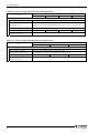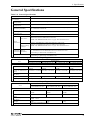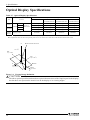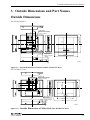
1
IPC Series
Flat Panel Display
IPC-DT/61 Series
User’s Manual
CONTEC CO.,LTD.
Copyright
Copyright 2004 CONTEC CO., LTD. ALL RIGHTS RESERVED.
No part of this document may be copied or reproduced in any form by any means without prior written
consent of CONTEC CO., LTD.
CONTEC CO., LTD. makes no commitment to update or keep current the information contained in this
document. The information in this document is subject to change without notice.
All relevant issues have been considered in the preparation of this document. Should you notice an
omission or any questionable item in this document, please feel free to notify CONTEC CO., LTD.
Regardless of the foregoing statement, CONTEC assumes no responsibility for any errors that may
appear in this document nor for results obtained by the user as a result of using this product.
Trademarks
MS, Microsoft, MS-DOS and Windows are trademarks of Microsoft Corporation. Other brand and
product names are trademarks of their respective holder.
User’s Manual
i
Table of Contents
Copyright ............................................................................................................................................. i
Trademarks .......................................................................................................................................... i
Table of Contents................................................................................................................................ ii
1.
Introduction
1
Features ............................................................................................................................................... 1
Customer Support ............................................................................................................................... 2
Web Site....................................................................................................................................... 2
Limited One-Year Warranty............................................................................................................... 2
How to Obtain Service ....................................................................................................................... 2
Liability .............................................................................................................................................. 2
Safety Precautions .............................................................................................................................. 2
Safety Information ....................................................................................................................... 3
Handling Precautions................................................................................................................... 3
2.
Specifications
7
Function Specifications ...................................................................................................................... 7
General Specifications ........................................................................................................................ 9
Optical Display Specifications ......................................................................................................... 10
3.
Outside Dimensions and Part Names
11
Outside Dimensions.......................................................................................................................... 11
Part Names ........................................................................................................................................ 15
Analog RGB Connector............................................................................................................. 18
RS Touch Panel Connector........................................................................................................ 18
USB Touch Panel Connector..................................................................................................... 19
DVI-D Connector ...................................................................................................................... 20
4.
Hardware Setup
21
Installation Requirements ................................................................................................................. 21
Panel Cut........................................................................................................................................... 21
Attaching the Fitting Used to Attach to the Main Unit ............................................................. 23
5.
Connection to the Host Computer
25
Analog RGB Connection .................................................................................................................. 25
DVI-D Connection ........................................................................................................................... 26
Touch Panel Data Communications ................................................................................................. 29
ii
User’s Manual
6.
Power Supply Connection
31
AC input type ................................................................................................................................... 31
DC input type ................................................................................................................................... 32
Power Supply Connector ........................................................................................................... 32
AC Adapter Jack........................................................................................................................ 33
AC adapter code removal prevention fitting .................................................................................... 34
7.
Screen Adjustment and a Setup
35
Menu Screen ..................................................................................................................................... 35
Direct Key......................................................................................................................................... 40
Memory of a Setting Value .............................................................................................................. 40
8.
LED Indicators
41
9.
Touch Panel
43
USB Multi-Touch Panel ................................................................................................................... 44
10.
Display Mode
45
11.
Options
47
User’s Manual
iii
iv
User’s Manual
1. Introduction
1. Introduction
This product is a dual-input (analog RGB and DVI-D), panel-mounted, color TFT LCD display unit for use
with host computers such as the CONTEC IPC series and SBCs (single board computers).
Features
-
Full-bright, wide-angle-of-visibility type of liquid crystals capable of displaying up to 262,144
colors (16,777,216 colors on the IPC-DT/H61XT-DC1 and AC0)
-
Standard analog RGB input for screen. RS-232C and USB interfaces for touch panel.
-
Multiple touch panel configurations containing up to eight touch panels are supported when using
the USB touch panel interface.
-
Auto-scaling feature that resizes the input screen to the LCD dot configuration.
-
On-screen display setup menu facilitating screen adjustment
-
Dual-input function supports analog RGB and DVI-D inputs. The display can be connected to two
different computers at once. (Simultaneous display is not supported. Screens are switched using the
OSD.)
-
Analog touch panel enabling mouse emulation using driver software
-
Optional AC adapter (IPC-ACAP12-01) available for AC power supply.
-
Front structure with IP65-compliant ingress protection
-
Optional stand kit available for desktop use.
-
A special fitting is provided to prevent the AC adapter cable from being unplugged.
User’s Manual
1
1. Introduction
Customer Support
CONTEC provides the following support services for you to use CONTEC products more efficiently and
comfortably.
Web Site
Japanese http://www.contec.co.jp/
English http://www.contec.com/
Chinese http://www.contec.com.cn/
Latest product information
CONTEC provides up-to-date information on products.
CONTEC also provides product manuals and various technical documents in the PDF.
Free download
You can download updated driver software and differential files as well as sample programs available in
several languages.
Note! For product information
Contact your retailer if you have any technical question about a CONTEC product or need its price,
delivery time, or estimate information.
Limited One-Year Warranty
CONTEC Products are warranted by CONTEC CO., LTD. to be free from defects in material and
workmanship for up to one year from the date of purchase by the original purchaser.
Repair will be free of charge only when this device is returned freight prepaid with a copy of the original
invoice and a Return Merchandise Authorization to the distributor or the CONTEC group office, from
which it was purchased.
This warranty is not applicable for scratches or normal wear, but only for the electronic circuitry and
original products. The warranty is not applicable if the device has been tampered with or damaged
through abuse, mistreatment, neglect, or unreasonable use, or if the original invoice is not included, in
which case repairs will be considered beyond the warranty policy.
How to Obtain Service
For replacement or repair, return the device freight prepaid, with a copy of the original invoice. Please
obtain a Return Merchandise Authorization Number (RMA) from the CONTEC group office where you
purchased before returning any product.
* No product will be accepted by CONTEC group without the RMA number.
Liability
The obligation of the warrantor is solely to repair or replace the product. In no event will the warrantor
be liable for any incidental or consequential damages due to such defect or consequences that arise from
Safety Precautions. Understand the following definitions and precautions to use the product safely.
Safety Precautions
Understand the following definitions and precautions to use the product safely.
2
User’s Manual
1. Introduction
Safety Information
This document provides safety information using the following symbols to prevent accidents resulting in
injury or death and the destruction of equipment and resources. Understand the meanings of these labels
to operate the equipment safely.
DANGER
DANGER indicates an imminently hazardous situation which, if not avoided, will
result in death or serious injury.
WARNING
WARNING indicates a potentially hazardous situation which, if not avoided, could
result in death or serious injury.
CAUTION
CAUTION indicates a potentially hazardous situation which, if not avoided, may
result in minor or moderate injury or in property damage.
Handling Precautions
CAUTION
-
As this product contains precision electronic components, do not use or store in environments
subject to shock or vibration.
-
Do not use or store the product in a location such as extremely high or low temperature, rapid
temperature changes, and the place which receives a strong ultraviolet ray.
Example: - Exposure to direct sun
- In the vicinity of a heat source
-
Some products require configuration settings. Always check these requirements before use. Also,
never set switches or jumpers to other than the specified settings as this may cause a fault.
-
Do not use or store the equipment in a dusty or humid place.
-
If you discover damaged or missing items, contact your retailer.
-
Do not perform key operations with the touch panel to implement a process that might endanger life
or result in serious damages. Design a system that can cope with incorrect key input operations.
-
Do not use a sharp-edged object, such as a mechanical pencil, to operate the touch panel in order to
prevent scratching or malfunctions.
-
Protect the touch panel against shock to prevent damage.
-
CONTEC is not liable for a product that has been modified by the user.
-
For this equipment, use the dedicated power supply unit if possible. If you connect any other power
supply unit, be sure to select the one that satisfies the voltage and current capacity standards.
-
Never supply power to the power supply connector and the AC adapter jack at the same time as it
can cause a fault.
User’s Manual
3
1. Introduction
-
When the surface or frame of the touch panel has become dirty, wipe it with neutral detergent. Do
not wipe the touch panel with thinner, alcohol, ammonia, or a strong chlorinated solvent.
-
Do not plug or unplug the connector with the equipment powered on. as doing so may result in a
malfunction or fault.
-
This product is not intended for use in aerospace, space, nuclear power, medical equipment, or other
applications that require a very high level of reliability. Do not use the product in such applications.
-
If you utilize this product in such usages where high reliability and safety are required as on the
trains, vessels, automotives or crime- or disaster-prevention devices, contact your retailer.
Use environment
This product operates under the following operating systems:
Windows XP/2000/NT 4.0/98SE/95OSR2, MS-DOS 6.2
* The touch panel USB interface is only supported on Windows XP/2000/98SE.
Life expectancy of components
*
(1) Backlight--- Display brightness decreases over time with use. The operating life of the backlight
(brightness reduced to 50% of original) is 50,000 hours for all models. (Assuming
continuous operation at 25 degrees centigrade.)
(2) Touch panel--- The operating lifetime of the touch panel is at least 1 million touches (as tested by
mechanical touching under 300g of force at a rate of two presses per second).
(3) Power supply (AC adapter) --- Expected life is six years for continuous operation at 40°C (when
mounted horizontally). However, this life may be reduced
depending on the operating temperature (in the case of higher
temperatures).
CONTEC accepts your request for replacing each consumable in the PANECON-PC as a request for
repair (at an additional cost). Contact your local retailer or CONTEC sales office.
LCD Display Pixel Drop
LCD display may have some pixels being dropped (bright and black spots) below a certain threshold.
Note that this is not a failure or a defect.
Burn-in on TFT Display
"Burn-in" may occur if the same display is retained for a long time. Avoid this by periodically
switching the display so that the same display is not maintained for a long time.
*
Burn-In: Phenomenon characterized by a TFT display as a result of long-time display of the same
screen where a shadow-like trace persists because electric charge remains in the LCD element even
after the patterns are changed.
4
User’s Manual
1. Introduction
Connecting to a host with an existing touch panel function such as a CONTEC panel computer.
This touch panel cannot be used with a touch panel mounted in the host computer. In this case, the
touch panel function will be unavailable but screen display will still work normally.
However, on the following CONTEC panel computers, multiple touch panels can be used together
when connected via the USB interface.
-
IPC-PT/630 Series: IPC-PT/H630X(PCI)C, IPC-PT/H630X(PCI)CP ,
IPC-PT/L630S(PCI)C, IPC-PT/L630S(PCI)CP
-
IPC-PT/620 Series: IPC-PT/H620X(PCW)C, IPC-PT/H620X(PCW)CP ,
IPC-PT/L620S(PCW)C, IPC-PT/L620S(PCW)CP
-
IPC-PT/600 Series: IPC-PT/H600X(PCW)C, IPC-PT/H600X(PCW)P ,
IPC-PT/L600S(PCW)C, IPC-PT/L600S(PCW)P
User’s Manual
5
1. Introduction
6
User’s Manual
2. Specifications
2. Specifications
Function Specifications
Table 2.1. Function Specifications
Specification
Item
IPC-DT/S61VT-DC1
IPC-DT/M61VT-DC1
IPC-DT/L61SVT-DC1
IPC-DT/H61XT-DC1
IPC-DT/M61VT-AC0
IPC-DT/L61SVT-AC0
IPC-DT/H61XT-AC0
Screen
Assembly type
Panel mounted, desktop *1
Screen size
6.5 inches
10.4 inches
12.1 inches
15.0 inches
Number of pixels
640 x 480 dots
640 x 480 dots
800 x 600 dots
1024 x 768 dots
Display type
TFT Color LCD
Number of colors
262,144 colors
262,144 colors
262,144 colors
16,777,216 colors
Screen adjustment
Automatic adjustment (display positioning and scaling) and manual
adjustment using the front switches
Brightness control
Adjustment using the front switch or software control from the host computer
Backlight control
Can be turned on or off by an OSD switch or via software control from the host
computer.
Display interface
Analog RGB input HD-SUB 15 pin (Female) connector
DVI-D input 24 pin DVI (Female) connector
Incoming
Analog
signal
RGB input
specification
Separate RGB, analog, positive polarity 0.7Vp-p/75Ω
Separate V/H, TTL, positive/negative polarity
Horizontal: 31 - 80kHz, vertical: 56 - 75Hz
DVI-D input
Digital RGB (complies with TMDS) *2
Cable length which recommends 5mm or less *3
Touch panel
Resolution
4096 x 4096
Detection method
Resistive-layer analog method
Touch life expectancy
One million repeated touches (silicon rubber load of 3 N)
Touch panel interface
Connect to the host computer using either USB*4 or RS-232C.
USB: USB1.1-compliant, TypeB Connector
RS-232C: 9pin D-SUB (Male) Connector
Touch panel driver
(option)
For Windows: IPC-SLIB-01
For MS-DOS: IPC-TPB1-DRV
*1 Optional desk stand IPC-SND-03 allowing desktop installation
*2 If the output is from a CONTEC IPC series or SBC series model, an ISA bus type panel link I/F board
(ADPLNK(PC)H) is required for some models. Please confirm before purchasing.
*3 Using a cable longer than 5 m may reduce the image quality. The cable should be as short as possible as
degradation. in image quality may result even when the cable is 5 m or shorter depending on the type of host
computer or cable.
*4 The touch panel USB interface is only supported on Windows XP/2000/98SE.
User’s Manual
7
2. Specifications
Table 2.2. Power Supply Specifications (DC Input Type)
Specification
Item
IPC-DT/S61VT-DC1
IPC-DT/M61VT-DC1
IPC-DT/L61SVT-DC1
IPC-DT/H61XT-DC1
Power supply input part
Power supply connector
4-pin nylon connector for 12 VDC power supply
AC adapter jack
AC adapter jack for 12 VDC power supply
(An optional AC adapter (IPC-ACAP12-01) can be used for 100 - 240VAC
input.)
Input power supply voltage
+12VDC±5%
Consumption current
1.3A(Max.)
Consumption current
(power save mode)
0.4A(Max.)
1.4A(Max.)
1.6A(Max.)
2.5A(Max.)
Table 2.3. Power Supply Specifications (AC Input Type)
Item
Specification
IPC-DT/M61VT-AC0
IPC-DT/L61SVT-AC0
IPC-DT/H61XT-AC0
Power supply input part
8
Power supply connector
Three-pin terminal block for the AC power supply
Input power supply voltage
Auto-switched 85 - 132VAC / 170 - 265VAC (47 - 63Hz) input
Power consumption
36VA (Max.)
Current consumption
(power save mode)
14VA (Max.)
40VA (Max.)
60VA (Max.)
User’s Manual
2. Specifications
General Specifications
Table 2.4. General Specifications
Item
Specification
Environment
Operating
temperature
Storage
temperature
Operating humidity
0 - 50ºC (0 - 40ºC when using an IPC-ACAP12-01 (AC switching adapter))
-10 - 60ºC
(20 - 80% when using an IPC-ACAP12-01 (AC switching adapter))
(No condensation allowed)
Floating dust
Normal
Corrosive gas
None
Line noise
Noise
resistance
AC line: 2 kV, Signal line: 1 kV
(IEC1000-4-4Level3, EN61000-4-4Level3)
(HOST: IPC-BX/M600(PCW) Power supply: IPC-POA200/12-01)
Contact: 4 kV(IEC1000-4-2Level2, EN61000-4-2Level2)
Electrostatic Airborne: 8 kV(IEC1000-4-2Level3, EN61000-4-2Level3)
withstanding (HOST: IPC-BX/M600(PCW) Power supply: IPC-POA200/12-01)
voltages
Vibration Sweep
resistance durability
Shock resistance
10 - 57 Hz/Single-side amplitude or 0.15 mm
57 - 150 Hz/2.0 G in the X/Y/Z directions for 23 minutes each
(Conforming to JIS C0040 and IEC68-2-6)
10 G in the X/Y/Z directions for 11 ms; Half-sine wave
(Conforming to JIS C0041 and IEC68-2-27)
Table 2.5. Structure specification (DC Input Type)
Item
Specification
IPC-DT/S61VT-DC1 IPC-DT/M61VT-DC1 IPC-DT/L61SVT-DC1 IPC-DT/H61XT-DC1
Structure
Major dimension (mm) 210(W) x 40(D) x
166(H)
305(W) x 43.5(D) x
240(H)
Panel cut dimensions
(mm)
Mountable panel
thickness
Weight
199.0(W) x 155.0(H) 292.0(W) x 227.0(H)
Ingress protection
Front part conforming to IP65
316(W) x 46.5(D) x
256(H)
376(W) x 46(D) x
305(H)
303.0(W) x 243.0(H)
358.0(W) x 289.0(H)
2.9kg
3.9kg
1.6mm - 7mm
1.3kg
2.6kg
Table 2.6. Structure specification (AC Input Type)
Item
Specification
IPC-DT/M61VT-AC0
IPC-DT/L61SVT-AC0
IPC-DT/H61XT-AC0
Structure
Major dimensions (mm)
305(W) x 51.5(D) x
240(H)
316(W) x 54.5(D) x
256(H)
376(W) x 54(D) x
305(H)
Panel cut dimensions
(mm)
Mountable panel
thickness
292.0(W)×227.0(H)
303.0(W)×243.0(H)
358.0(W)x289.0(H)
3.1kg
4.1kg
1.6mm - 7mm
Weight
2.8kg
Ingress protection
Front part conforming to IP65
User’s Manual
9
2. Specifications
Optical Display Specifications
Table 2.7. Optical Display Specifications
Specifications (25ºC Typ. Value)
Item
Condition
Visual angle
(vertical)
Visual angle
(horizontal)
Surface
brightness
(at center)
IPC-DT/S61VT-DC1
φ=180°
CR≥10
φ=0°
φ=+90°
Display in
monochrome
φ=-90°
Display in white
IPC-DT/M61VT-DC1
IPC-DT/L61SVT-DC1
IPC-DT/H61XT-DC1
IPC-DT/M61VT-AC0
IPC-DT/L61SVT-AC0
IPC-DT/H61XT-AC0
45deg
50deg
50deg
45deg
35deg
70deg
70deg
55deg
50deg
70deg
70deg
60deg
50deg
70deg
70deg
60deg
300cd/m 2
400cd/m 2
350cd/m 2
260cd/m 2
*1 Surface brightness is a numerical value in a display simple substance.
The brightness that let the touch panel pass serves as about 75% of the above-mentioned numerical value.
Measurement direction
Z
( θ = 0o )
Left
( φ = -90o )
θ
Top
( φ = 180o )
X
φ
Module
Bottom
( φ = 0o )
Right
( φ = 90o )
Y
Figure 2.1. Viewing Range Definition
CAUTION
The above optical specification data shows optical characteristics of the liquid crystal in the display;
the data does not represent the actual view on the display or its viewing angles.
10
User’s Manual
3. Outside Dimensions and Part Names
3. Outside Dimensions and Part Names
Outside Dimensions
IPC-DT/S61VT-DC1
4-M4 TAP
(Maximum tapping
length : 5mm)
27
PASS
166
154
INS PECT
DVI
75
XXXXXXXXX
MODEL : XXXXXXXXXXXXXXXXXX
SERIAL No. : XXXXXXXXXXXXX
INPUT : XXXXXXXXXXXXXXXXXX
105
58
VGA
USB
75
COM
XXXXXXXXX
XXXXXXXXX
CAUTION!
2
12VDC-IN
1
*************
******0.6N*m***
The screw bolting torque of attachment
-
MENU
+
ESC
POWER
must be 0.6N-m(MAX)
198
50
M3 TAP
(Maximum
tapping length
: 5mm)
138
210
CAU TION!
Do n't co n ne c t 1 and 2 of
12V D C -IN s im ultan eo us ly.
16
35
12V D C -I N* 1*2* * *
* ** * ** * ** * **
5
[mm]
Figure 3.1. Outside Dimensions of Main Unit(IPC-DT/S61VT-DC1)
IPC-DT/M61VT-DC1
8-M4 TAP
(Maximum tapping
length : 5mm)
87.7
240
163.4
- +
FG
12 VDC- IN*1 *2***
************
CAUTI ON!
Don't con nect 1 and 2 of
12V DC-IN simultaneou sl y.
2
12VDC-IN 1
COM
226
DVI
27.5
100
6.5
75
VGA
USB
100
75
MENU
-
+
ESC
POWER
216.2
305
5
38.5
49
18.5
291
M3 TAP
(Maximum
tapping length
: 5mm)
Figure 3.2.
[mm]
Outside Dimensions of Main Unit (IPC-DT/M61VT-DC1)
User’s Manual
11
3. Outside Dimensions and Part Names
IPC-DT/L61SVT-DC1
8-M4 TAP
(Maximum tapping
length : 5mm)
96.8
256
189.5
242
- +
FG
2
CAUT ION!
D on't con nect 1 an d 2 of
1 2VDC -IN sim u lta neou sl y.
12VD C- IN *1*2***
****** ******
6.5
12VDC-IN 1
COM
27.5
DVI
100
75
VGA
USB
100
75
MENU
M3 TAP
(Maximum tapping
54.5 length : 5mm)
+
ESC
POWER
41.5
251
316
[mm]
5
21.5
302
-
Figure 3.3. Outside Dimensions of Main Unit (IPC-DT/L61SVT-DC1)
41
21
5
IPC-DT/H61XT-DC1
123
305
233
288
COM
DVI
100
75
VGA
U
SB
220
357
ME NU
8-M4 TAP
(Maximum tapping
length : 5mm)
75
100
M3 TAP
(Maximum tapping
length : 5mm)
-
+
E SC
P OWER
309
376
[mm]
Figure 3.4. Outside Dimensions of Main Unit (IPC-DT/H61XT-DC1)
12
User’s Manual
3. Outside Dimensions and Part Names
IPC-DT/M61VT-AC0
8-M4 TAP
(Maximum tapping
length : 5mm)
87.7
240
163.4
226
39.3
DVI
COM
67.4
N
L
6.5
27.5
100
75
VGA
USB
100
75
MENU
5 38.5 8
49
67.5
18.5
291
148
-
+
ESC
POWER
216.2
305
[mm]
Figure 3.5. Outside Dimensions of Main Unit (IPC-DT/M61VT-AC0)
IPC-DT/L61SVT-AC0
8-M4 TAP
(Maximum tapping
length : 5mm)
96.8
256
189.5
242
40.3
DVI
COM
67.4
N
L
6.5
27.5
100
75
VGA
USB
100
75
54.5
21.5
67.5
Figure 3.6.
5 41.5 8
MENU
302
148
-
+
ESC
POWER
251
316
[mm]
Outside Dimensions of Main Unit (IPC-DT/L61SVT-AC0)
User’s Manual
13
3. Outside Dimensions and Part Names
21
123
305
233
288
69.3
N
L
CO M
DV I
100
75
VGA
U SB
67.4
8
148
220
357
41 5
IPC-DT/H61XT-AC0
MENU
8-M4 TAP
(Maximum tapping
length : 5mm)
75
100
-
+
ES C
POWER
309
376
[mm]
Figure 3.7. Outside Dimensions of Main Unit (IPC-DT/H61XT-AC0)
14
User’s Manual
3. Outside Dimensions and Part Names
Part Names
Front
MENU
-
+
Screen & Touch panel
ESC
Screen adjustment switch
Right side
POWER
POWER LED
Left side
USB
USB touch panel connector
VGA
Analog RGB connector
DVI
Back
DVI-D connector
XXXXXXXXX
MODEL : XXXXXXXXXXXXXXXXXX
SERIAL No. : XXXXXXXXXXXXX
INPUT : XXXXXXXXXXXXXXXXXX
INSPECT
PA S S
2
12VDC-IN
1
CAUTION!
The screw bolting torque
of attachment must be
0.6N-m(MAX).
COM
XXXXXXXXX
XXXXXXXXX
RS touch panel connector
AC adapter jack
+12VDC power connector
CAUTION!
Don't connec t 1 and 2 of
12V DC-IN simultaneously.
12V DC-IN*1*2***
************
Figure 3.8. Part Names(IPC-DT/S61VT-DC1)
User’s Manual
15
3. Outside Dimensions and Part Names
Front
Screen & Touch panel
MENU
-
+
Screen adjustment switch
POWER
POWER LED
Left side
Back
CAUTION!
-
USB touch panel connector
Analog RGB connector
DVI-D connector
RS touch panel connector
AC adapter jack
+12VDC power connector
12VDC-IN*1 *2***
******** ****
D on't connect 1 and 2 of
12 VDC- IN simultaneousl y.
F
2
+
12VDC-IN 1
COM
DV
VGA
USB
Right side
ESC
Figure 3.9. Part Names(IPC-DT/M61VT-DC1, IPC-DT/L61SVT-DC1, IPC-DT/H61XT-DC1)
16
User’s Manual
3. Outside Dimensions and Part Names
Front
Screen & Touch panel
MENU
-
+
Screen adjustment switch
POWER
POWER LED
Back
Left side
N
L
COM
DV
VGA
USB
Right side
ESC
USB touch panel connector
Analog RGB connector
DVI-D connector
RS touch panel connector
AC power supply terminals
Figure 3.10. Part Names(IPC-DT/M61VT-AC0, IPC-DT/L61SVT-AC0, IPC-DT/H61XT-AC0)
User’s Manual
17
3. Outside Dimensions and Part Names
Analog RGB Connector
Table 3.1. Analog RGB Connector
Connector type
15-pin HD-SUB (FEMALE)
1
5
10
6
15
11
Pin NO.
Signal name
Pin NO.
1
RED
9
Signal name
N.C.
2
GREEN
10
GND
3
BLUE
11
N.C.
4
N.C.
12
DDC DATA
5
GND
13
HSYNC
6
R-GND
14
VSYNC
7
G-GND
15
DDC CLK
8
B-GND
RS Touch Panel Connector
This connector is RS-232C compliant to be used for touch panel data communication with the host
computer.
Table 3.2. RS Touch Panel Connector
Connector type
9-pin D-SUB (MALE)
1
5
6
18
9
Pin NO.
Signal name
Pin NO.
Signal name
1
10K pull down
6
10K pull down
2
TxD
7
N.C.
3
RxD
8
10K pull down
4
N.C.
9
10K pull down
5
GND
User’s Manual
3. Outside Dimensions and Part Names
USB Touch Panel Connector
The USB connector for communication between the host computer and touch panel.
Table 3.3. USB Touch Panel Connector
Connector type
USB Type B (Receptacle)
2
1
3
4
Pin NO.
Signal name
Pin NO.
Signal name
1
+5V
3
DATA+
2
DATA-
4
GND
User’s Manual
19
3. Outside Dimensions and Part Names
DVI-D Connector
Table 3.4. DVI-D Connector
Connector
DVI-I 24pin
9
Pin No.
20
1
8
17
24
Signal name
16
Pin No.
Signal name
1
TMDS
DATA2-
13
N.C.
2
TMDS
DATA2+
14
+5V
3
TMDS
DATA2
SHIELD
15
GND
4
N.C.
16
HPD
5
N.C.
17
TMDS
DATA0-
6
DDC CLK
18
TMDS
DATA0+
7
DDC
DATA
19
TMDS
DATA0
SHIELD
8
N.C.
20
TXD
9
TMDS
DATA1-
21
RXD
10
TMDS
DATA1+
22
TMDS
DATA0
SHIELD
11
TMDS
DATA1
SHIELD
23
TMDS
CLK+
12
N.C.
24
TMDS
CLK-
User’s Manual
4. Hardware Setup
4. Hardware Setup
Installation Requirements
To maintain the ambient temperature within the installation environment requirement range, provide a
gap of 30mm or more between the main unit and any adjacent equipment.
Side view
Panel
30mm or more(above)
Bottom view
30mm or more(Side)
Interface surface
30mm or more
(Bottom)
CAU TION!
Do n't co n n ec t 1 and 2 o f
12V D C -I N s im ultan e o u sly.
12V DC -I N* 1* 2** *
* ** * ** * ** * * *
Panel
30mm or more(back)
Figure 4.1. Distances Between Computer and Surroundings
Panel Cut
Cut the display mount panel in the following dimensions. The four corners of the solid-line rectangle
define the panel cut dimensions.
155 +1
-0
199 +1
-0
Panel thickness range: 1.6 to 7mm
[mm]
Figure 4.2. IPC-DT/S61VT-DC1 Panel Cut Dimensions
User’s Manual
21
4. Hardware Setup
227 +1
-0
292 +1
-0
Panel thickness range: 1.6 to 7mm
[mm]
Figure 4.3. IPC-DT/M61VT-DC1, IPC-DT/M61VT-AC0 Panel Cut Dimensions
303 +1
-0
243 +1
-0
R1 or less
Panel thicknes range: 1.6 to 7mm
[mm]
Figure 4.4. IPC-DT/L61SVT-DC1, IPC-DT/L61SVT-AC0 Panel Cut Dimensions
358 +1
-0
289 +1
-0
R1 or less
Panel thickness range: 1.6 - 7mm [mm]
Figure 4.5. IPC-DT/H61XT-DC1, IPC-DT/H61XT-AC0 Panel Cut Dimensions
22
User’s Manual
4. Hardware Setup
Attaching the Fitting Used to Attach to the Main Unit
(1) Hold the main unit from the outside of the panel.
Figure 4.6. Attaching the Fitting Used to Attach to the Main Unit < 1 / 2 >
(2) Hold the attach from the inside of the panel.
Metal fittings
Panel
Main body
Overtightening screws may result in damage.
Example of figure:IPC-DT/M61VT-xxx
Figure 4.6. Attaching the Fitting Used to Attach to the Main Uni < 2 / 2 >
User’s Manual
23
4. Hardware Setup
24
User’s Manual
5. Connection to the Host Computer
5. Connection to the Host Computer
Purchase individual connection cables as they are not bundled with this equipment.
Analog RGB Connection
Connect the analog RGB input on this unit to the analog RGB connectors on the host computer.
Table 5.1. Recommendation Display Cable
Model
Maker
Cable length
KC-V2
SANWA SUPPLY INC.
2m
KC-V5
SANWA SUPPLY INC.
5m
If you use any other cable, select a shielded cable the wire carrying the RGB and H/Vsync signals and the
grounded wire in a twisted pair. Note that a non-twisted-pair cable may degrade image quality, in
particular, which is longer than 2 m.
Any loss of image quality due to use of a cable other than the recommended cable or its equivalent is not
covered by warranty.
User’s Manual
25
5. Connection to the Host Computer
DVI-D Connection
Connect the DVI-D input on this unit to the DVI-D connector on the host computer or the PanelLink
connector. You can use a CONTEC IPC series or SBC (single board computer) as the host computer. In
this case, settings are required on each host computer.
Set the LCD type as follows depending on the host computer to be used.
When connecting to a SPI-6940-LLVA
To use this SBC board with the display, set the on-board switch (SW1) as shown below.
Table 5.2. SW1 Switch Settings
IPC-DT/S61VT-DC1
IPC-DT/M61VT-DC1
IPC-DT/M61VT-AC0
ON
1
IPC-DT/L61SVT-DC1
IPC-DT/L61SVT-AC0
ON
2 3 4
1
IPC-DT/H61XT-DC1
IPC-DT/H61XT-AC0
ON
2 3 4
ON
1 2 3 4
1 2 3 4
CAUTION
Use this board along with the LCD signal conversion board [ADP-6940].
When connecting to a PC-686BX(PC)-LV
To use this SBC board with the display, set the on-board switch (U2) as shown below.
Table 5.3. U2 Switch Settings
IPC-DT/S61VT-DC1
ON
IPC-DT/M61VT-DC1
IPC-DT/M61VT-AC0
ON
1 2 3 4 5 6 7 8
1 2 3 4 5 6 7 8
IPC-DT/L61SVT-DC1
IPC-DT/L61SVT-AC0
ON
1 2 3 4
IPC-DT/H61XT-DC1
IPC-DT/H61XT-AC0
ON
5 6 7 8
1 2 3 4
5 6 7 8
CAUTION
When using this board, also use an ISA bus type panel link I/F board (ADPLNK(PC)H).
26
User’s Manual
5. Connection to the Host Computer
When connecting to a PC-686E(PC)-LV
To use this SBC board with the display, set the on-board rotary switch as shown below.
Table 5.4. Rotary Switch Setting Number
IPC-DT/S61VT-DC1
IPC-DT/M61VT-DC1
IPC-DT/M61VT-AC0
IPC-DT/L61SVT-DC1
IPC-DT/L61SVT-AC0
IPC-DT/H61XT-DC1
IPC-DT/H61XT-AC0
2
2
0
1
CAUTION
When using this board, also use an ISA bus type panel link I/F board (ADPLNK(PC)H).
When connecting to a PC-586U(PC)-LV, PC-586U(PC)-LVS
To use this SBC board with the display, set the on-board switch (S2) as shown below.
Table 5.5. S2 Switch Settings
IPC-DT/S61VT-DC1
ON
1
IPC-DT/M61VT-DC1
IPC-DT/M61VT-AC0
ON
2 3 4
1
IPC-DT/L61SVT-DC1
IPC-DT/L61SVT-AC0
ON
2 3 4
IPC-DT/H61XT-DC1
IPC-DT/H61XT-AC0
ON
1 2 3 4
1 2 3 4
CAUTION
When using this board, also use an LCD connector conversion board (EXLCD68) or an ISA bus type
panel link I/F board (ADPLNK(PC)H).
When connecting to a PC-586HU(PC)-LV
To use this SBC board with the display, set the on-board switch (J8) as shown below.
Table 5.6. J8 Switch Settings
IPC-DT/S61VT-DC1
IPC-DT/M61VT-DC1
IPC-DT/M61VT-AC0
IPC-DT/L61SVT-DC1
IPC-DT/L61SVT-AC0
IPC-DT/H61XT-DC1
IPC-DT/H61XT-AC0
7
1
7
1
7
1
7
1
8
2
8
2
8
2
8
2
* All is open.
CAUTION
When using this board, also use an ISA bus type panel link I/F board (ADPLNK(PC)H).
User’s Manual
27
5. Connection to the Host Computer
When connecting to a IPC-BX/M600(PCW) Series
If using this box computer, set the "Embedded" - "CRT/FPD" BIOS setting to "AUTO Select" or "SW
Select". If you select "SW Select", set the switch (S1) on the box computer board as shown below.
Table 5.7. S1 Switch Settings
IPC-DT/S61VT-DC1
ON
IPC-DT/M61VT-DC1
IPC-DT/M61VT-AC0
ON
1 2 3 4 5 6 7 8
IPC-DT/L61SVT-DC1
IPC-DT/L61SVT-AC0
ON
1 2 3 4 5 6 7 8
1 2 3 4
IPC-DT/H61XT-DC1
IPC-DT/H61XT-AC0
ON
5 6 7 8
1 2 3 4
5 6 7 8
When connecting to a IPC-BX/M630(PCI) Series
No specific host settings are required if using this box computer. However, if using the Windows XP
operating system, only connect the analog RGB cable during installation. Change to the DVI connection
after installation completes.
When connecting to a IPC-BX/M360(PCI)C Series
When using this box computer, set the size of the connecting display by selecting “Advanced Chipset
Features Setup” – “Panel Type” in the BIOS setting section.
Example) For IPC-DT/L6xSVT-xx : “800 x 600”
CAUTION
If connecting this display to a product with the “AUTO Select” function such as
IPC-BX/M600(PCW) and IPC-BX/M360(PCI)C, or to a product with the “plug and play” function
such as the IPC-BX/M630(PCI) series, first connect cables, then turn on the display, always before
turning on the host computer. If the host computer is started before the display, it may not be able to
read the information on the display, and as a result, no screen image may come up.
In this case (e.g. when the display is turned on afterward, when a cable is connected afterward),
specify the display size in the BIOS settings on the host computer.
28
User’s Manual
5. Connection to the Host Computer
Touch Panel Data Communications
These connections are used to send touch panel data to the host computer via the USB or RS-232C serial
port. Connect to the USB port or serial port (COM port) on the host computer.
Table 5.8. Example of a USB connection cable (USB Type A(Host) Û Type B(Display)cable)
Model
Maker
Cable length
KU20-2H
SANWA SUPPLY INC.
2m
KU20-5H
SANWA SUPPLY INC.
5m
Table 5.9. Option Cable (RS-232C Straight Cable)
Model
Maker
Cable length
IPC-CBL3-2
CONTEC
2m
IPC-CBL3-5
CONTEC
5m
CAUTION
-
The RS-232C cable is not required if using the DVI-D input with a CONTEC host computer because
the DVI-D interface includes the RS-232C signal lines. Note that connecting the RS-232C cable
causes the touch panel to stop working.
-
Touch panel driver software is required to use the touch panel. Purchase optional driver software
[IPC-SLIB-01 for windows or IPC-TPB1-DRV for MS-DOS] or download one from the CONTEC’s
web site.
-
The USB touch panel driver software requires V1.40 or later of IPC-SLIB-01.
-
The USB connection can only be used on Windows XP, 2000, or 98SE. Connect via the RS-232C
interface if using a different OS.
-
Use either USB or RS-232C for connecting the touch panel. The touch panel cannot be connected
via both interfaces at the same time.
-
When using the USB connection, the screen image may disappear momentarily when the USB cable
is connected or disconnected and when the computer power is turned ON or OFF.
-
When using the USB connection via a hub, the unit may not operate correctly in some cases
depending on the other USB devices connected to the hub. Please check the operation before using
in practice.
User’s Manual
29
5. Connection to the Host Computer
30
User’s Manual
6. Power Supply Connection
6. Power Supply Connection
Two versions of this product are available that use AC input and DC input respectively for the power
supply. The power supply connector consists of a terminal block on the AC input type and a power
supply connector and AC adapter jack on the DC input type.
CAUTION
-
On the DC input type, input the power supply to the power supply connector only or the AC adapter
jack only. Never supply power to both of them at the same time as it can cause a fault.
-
If you connect a power supply other than the option, be sure to take safety measures for the power
supply, such as overvoltage protection. Use meticulous care not to mistake the connection polarity
or voltage of the power supply as it may break the equipment, the power supply, or both.
AC input type
Table 6.1. Power Supply Connector
Connector type
AC Input Terminals
1
2
- Screw diameter: M3.5, Terminal pitch: 9.5mm
3
- Terminal type
7.8
L
Pin No.
Signal name
1
FG(Frame Gnd)
2
N
3
L
6.2 3.9
N
Note: This product does not have an AC on/off switch.
User’s Manual
31
6. Power Supply Connection
DC input type
Power Supply Connector
When connecting the power supply, ensure that the supply satisfies the specifications below.
-
Power supply voltage: +12VDC 5%
-
Power supply capacity: 2.5A or more
The table below lists the pin specifications of the power connector on the back of the equipment.
Table 6.2. Power Supply Connector (IPC-DT/S61VT-DC1)
Connector type +12 VDC input connector
Model
B4PS-VH(manufactured by JST)
1
2
3
4
Pin No.
Signal name
1
GND
2
GND
3
+12V
4
+12V
Applicable power cable connector
Housing: VHR-4N (manufactured by JST)
Contact: SVH-21T-1.1(AWG22-18)
(manufactured by JST)
* Please obtain your own connector for the cable.
Table 6.3. Power Supply Connector (IPC-DT/M61VT-DC1, IPC-DT/L61SVT-DC1,
IPC-DT/H61XT-DC1)
Connector
type
+12VDC input connector
Model
DFK-MC1,5/3-GF-3,81
(PHOENIX CONTACT)
1 2
3
Pin No.
Signal name
1
FG(Frame Gnd)
2
GND
3
+12V
* Use the supplied MC1,5/3-STF-3,81 for the cable connector.
32
User’s Manual
6. Power Supply Connection
AC Adapter Jack
The AC adapter jack is used to connect the AC adapter [IPC-ACAP12-01] available as an option. Do not
connect any AC adapter other than the option.
+12V
GND
Figure 6.1. AC Adapter Jack
User’s Manual
33
6. Power Supply Connection
AC adapter code removal prevention fitting
(1) Insert the plug of AC Adapter.
(2) Tighten the screws on the attachment fitting.
Figure 6.2. Code Removal Prevention Fitting
34
User’s Manual
7. Screen Adjustment and a Setup
7. Screen Adjustment and a Setup
The equipment has screen adjustment switches [MENU], [+], and [-]. Use these switches to adjust the
screen. (For the locations of the switches, see “Part Names” in Chapter 3.) When using the equipment
for the first time or after changing the output screen mode of the host computer, execute AUTO ADJUST
first on the menu screen. Use these switches also to adjust the screen brightness and contrast and to make
settings for the touch panel.
Menu Screen
Pressing the [MENU] switch displays the main menu screen. Use the [+] and [-] switches to select
individual items, adjust them, then press the [MENU] to save the settings.
SCREEN MANAGER
BRIGHTNESS
R
G B
Othe
r
CONTRAST
DISPLAY ADJUST
COLOR CONTROL
OTHERS
TOUCH PANEL
INPUT SOURCE
RESET
640x480
60.0Hz
Analog RGB input
SCREEN MANAGER
BRIGHTNESS
Othe
r
V.POSITION SP
OTHERS
TOUCH PANEL
INPUT SOURCE
RESET
640x480
60.0Hz
DVI-D input
Figure 7.1. Main Menu Screen
Select this item to adjust the brightness of the backlight. Press [+] or [-] to optimize
BRIGHTNESS:
the item. The brightness can also be adjusted by pressing the [+] and [-] keys
without the MENU screen displayed, as the direct brightness control keys.
CONTRAST:
Select this item to adjust the contrast of the screen. Press [+] or [-] to optimize the
item.
User’s Manual
35
7. Screen Adjustment and a Setup
DISPLAY ADJUST:
Adjusts the display position. Selecting this item displays a sub-menu. Use [+]
and [-] to move between items and [MENU] to select.
SCREEN MANAGER
AA
H.POSITION
V.POSITION
V.POSITION SP
WIDTH
PHASE
AUTO SETUP
HORIZONTAL POSITION
640x480
60.0Hz
Figure 7.2. DISPLAY ADJUST Sub-Menu Screen
H.POSITION:
Select this item to adjust the horizontal position of the screen. Press [+] or [-]
while checking the screen to optimize the item.
V.POSITION:
Select this item to adjust the vertical position of the screen. Press [+] or [-]
while checking the screen to optimize the item.
V.POSITION SP:
Adjusts the position vertically. Use this item if the screen is offset or flickers
after using "AUTO SETUP" despite adjusting with "V.POSITION". Press [+]
or [-] while checking the screen to optimize the position.
WIDTH:
Select this item to adjust the horizontal display size of the screen. Press [+] or
[-] to optimize the item.
PHASE:
Adjust this item when the screen is partlyb lurred or flickering. Press [+] or [-]
while checking the screen to optimize the item.
AUTO SETUP:
Select AUTO ADJUST when using the equipment for the first time or when the
screen cannot be displayed normally due to a change made to the display mode.
Select this item and press [MENU] to accept your selection, and the equipment
starts performing automatic adjustment.
CAUTION
AUTO ADJUST may fail to adjust the screen correctly depending on the host computer or the
display screen (mostly black screen such as in the DOS text mode). In such a case, adjust POSITION
and WIDTH to manually optimize the screen.
36
User’s Manual
7. Screen Adjustment and a Setup
COLOR CONTROL: Adjusts the color temperature. Selecting this item displays a sub-menu. Use
[+] and [-] to move between items and [MENU] to select. You can select USER
COLOR MODE to adjust RED, GREEN, and BLUE manually.
SCREEN MANAGER
R
G B
9300 K
6500 K
5000 K
R
G B
R
G B
R
G B
USER
COLOR
MODE
COLOR TEMPERATURE
640x480
60.0Hz
Figure 7.3. COLOR CONTROL Sub-Menu Screen
OTHERS:
The display position and time etc. of the OSD screen can be adjusted. Selecting
this item displays a sub-menu. Use [+] and [-] to move between items and
[MENU] to select.
Figure 7.4. OTHERS Sub-Menu Screen
OSD H.POSITION: Adjusts the horizontal position of the OSD. Press the [+] or [-] while viewing
the screen to adjust the position.
OSD V.POSITION:
Adjusts the vertical position of the OSD. Press the [+] or [-] while viewing
the screen to adjust the position.
OSD TIMER:
Adjusts the display time for the OSD. Use [+] and [-] to adjust the time.
SILENT MODE:
SILENT MODE controls display message “No Input Signal" and “Power
Saving" of DISPLAY when it is effective.
INFORMATION:
Information on the input signal and version information on OSD are
displayed.
User’s Manual
37
7. Screen Adjustment and a Setup
TOUCHPANEL:
Select this item to adjust the status of the touch panel. Select this item to invoke the
submenu, select a desired item using [+] or [-], then press [MENU] to accept the
setting made.
SCREEN MANAGER
ON/OFF
DISPLAY ID
INTERVAL
MODE
BEEP
ID
Mode
TOUCH PANEL ON/OFF
640x480
60.0Hz
Figure 7.5. TOUCH PANEL sub menu
ON/OFF:
Select this item to turn ON (enable) or OFF (disable) the touch panel operation.
(The equipment is started always with this item set to OFF.) Usually, this item does
not have to be set as the touch panel is turned ON (enabled) automatically upon
startup of the touch panel driver. Note, however, that the touch panel does not
work when the equipment is connected to the host with the touch panel driver
already up and running or when the power to the equipment is recycled. In
suchcases, set this item to ON (enabled).
38
DISPLAY ID:
Set the ID to use for USB multi-touch panel operation. See Chapter 9 for details of
USB multi-touch panel operation. (Factory setting: 6)
INTERVAL:
Select this item to adjust the scan timing of the touch panel. Press [+] or [-] to
increase or decrease the response of the touch panel. (Factory setting: 5)
MODE:
Select the touch panel mode (WINDOWS or DOS) depending on the host OS. For
use in the MS-DOS environment (using the MS-DOS touch panel driver), be sure
to set this item to “DOS”. (Factory setting: WINDOWS)
BEEP:
Select this item to turn on or off the click tone of the touch panel. (Factory setting:
OFF)
When using the touch panel driver for Windows, the settings specified in the touch
panel driver are used instead.
User’s Manual
7. Screen Adjustment and a Setup
INPUT SOURCE: Selects the input signal. Selecting this item displays a sub-menu. Use [+] and [-]
to move between items and [MENU] to select.
SCREEN MANAGER
ANALOG RGB
DVI
ANALOG RGB
640x480
60.0Hz
Figure 7.6. INPUT SOURCE Sub-Menu Screen
ANALOG RGB:
Displays the input from the ANALOG RGB connector.
DVI:
Displays the input from the DVI connector.
RESET:
User’s Manual
Restores all settings to their factory defaults. Use this option to initialize the
settings if the screen display is lost or does not work correctly. You can also reset
the settings by holding down the [MENU] direct key when tuning on the power.
39
7. Screen Adjustment and a Setup
Direct Key
CONTRAST
:
Pressing the [+] key when the menu is not displayed opens the contrast
adjustment screen.
BRIGHTNESS
:
The brightness of the backlight can be adjusted by pressing the [+] and [-] keys
without the menu screen displayed.
RESET
:
All the settings can be reset to the factory defaults by turning on the equipment
while holding down the [MENU] key.
Power save mode
:
You can place the equipment in the power save mode by depressing both of the
[+] and [-] keys at the same time without the menu screen displayed. This can
force the screen display and backlight to be turned off. Release the buttons
when “POWER SAVE MODE…” appears on the screen. You can recover the
screen from the power save mode by pressing any of the front switches. The
power consumption of the equipment in the power save mode is about 1/5 of
that during normal operation. Turning off the backlight when not required the
backlight to extend its life.
*
Recycling the power to the equipment in the power save mode recovers it to the normal display state.
*
The POWER LED on the front face remains blinking in green in the power save mode.
Memory of a Setting Value
The equipment retains its settings even when the power is turned off. Note, however, that the following
settings are reset to their defaults without being retained.
- The power save mode setting made by the direct key is reset to the normal state when the power is
turned on.
-
40
The TOUCH PANEL ON/OFF setting is set to OFF when the power is turned on.
User’s Manual
8. LED Indicators
8. LED Indicators
The POWER LED on the front face indicates each state of the display as follows:
Table 8.1. LED Indicators
LED status
Description
OFF
The power supply off or the equipment not started normally
Green(ON)
Normal operation
Green
Power save mode
(Flashing)
Orange (ON) Unsupported signal input *1
Orange
(Flashing)
*1
No signal input *2
The LED looks like this when the equipment cannot process the input
signal to provide normal display, for example, when the
horizontal/vertical sync signal frequency is exceeding the supported
frequency. See Chapter 9 "Display mode" for the display modes
supported by this equipment.
*2
The LED looks like this also when the horizontal or vertical sync
signal is turned off by the power management function of the host
computer. The equipment enters the power save mode automatically
when no signal has been input for about two seconds.
User’s Manual
41
8. LED Indicators
42
User’s Manual
9. Touch Panel
9. Touch Panel
This equipment has a touch panel that enables keyboard-less, mouse-less operations by communication
with the host computer using the RS-232C cable.
Touch panel
MENU
-
+
ESC
POWER
Host PC
Touch panel controller
Communication controller
CPU
INT
Touch panel
CPU
Serial
communication
Figure 9.1. Touch Panel and Block Diagram
Data input at the touch panel is processed by the touch panel controller and passed to the host PC via the
serial port on the CPU in the controller.
Before the touch panel can be used, touch panel driver software must be installed. Note that the driver
software is not bundled with this product. Purchase the one separately or download it from the
CONTEC’s web site.
For further details, refer to the READ_ME file for each driver.
<Option touch panel driver>
Windows XP/2000/NT 4.0/98SE/95OSR2
: IPC-SLIB-01
MS-DOS 6.2
: IPC-TPB1-DRV
CAUTION
-
The USB touch panel driver software requires V1.40 or later of IPC-SLIB-01.
-
The USB connection can only be used on Windows XP, 2000, or 98SE. Connect via the RS-232C
interface if using a different OS.
-
Use either USB or RS-232C for connecting the touch panel. The touch panel cannot be connected
via both interfaces at the same time.
-
When using the USB connection, the screen image may disappear momentarily when the USB cable
is connected or disconnected and when the computer power is turned ON or OFF.
User’s Manual
43
9. Touch Panel
USB Multi-Touch Panel
This function can be used in the case when the RGB signal from the host computer is split for connecting
to multiple displays via a splitter. The function permits touch panel operation to be used at all the
displays. A maximum of eight touch panel displays can be connected.
Note that all touch panels must be connected via USB and, to allow the touch panel driver software on
the host computer to identify each device, a different USB ID must be set on the DIP switch located on
the side of each display unit.
USB ID7
RGB distributor
RGB cable
MENU
-
+
ESC
PO WER
8 sets(Max.)
USB ID0
Host PC
USB HUB
USB cable
MENU
-
+
ESC
PO WER
Touch panel display
Figure 9.2. Example of connection of a USB multi-touch panel
You can use a CONTEC IPC-PT/600 series panel computer as the host PC.
In this case, the ID of the touch panel in the panel computer is fixed at ID7. Set the IDs of the external
displays in the range USB ID0 - USB ID6 (a maximum of seven external displays can be connected).
CAUTION
You cannot use multiple touch panels via the RS-232C interface.
44
User’s Manual
10. Display Mode
10. Display Mode
This equipment supports the following display modes:
Table 10.1. Analog RGB Input - Display Modes
IPC-DT/H61XT-DC1,
IPC-DT/H61XT-AC0
IPC-DT/L61SVT-DC1,
IPC-DT/L61SVT-AC0
IPC-DT/M61VT-DC1,
IPC-DT/M61VT-AC0
IPC-DT/S61VT-DC1
Display
Dot clock
(MHz)
Horizontal
frequency
(kHz)
Vertical
frequency
(Hz)
640 x 350
25.18
31.47
70
Ο
Ο
Ο
Ο
720 x 400
28.32
31.47
70
Ο
Ο
Δ
Ο
VGA
VGA
VGA
640 x 480
25.18
31.47
60
O
O
VESA
640 x 480
31.50
37.86
72
Ο
Ο
Ο
Ο
VESA
640 x 480
31.50
37.50
75
Ο
Ο
Ο
Ο
VESA
800 x 600
36.00
35.16
56
Ο
Ο
Ο
Ο
VESA
800 x 600
40.00
37.88
60
Ο
Ο
VESA
800 x 600
50.00
48.08
72
Ο
Ο
Ο
Ο
VESA
800 x 600
49.50
46.88
75
Ο
Ο
Ο
Ο
VESA
1024 x 768
65.00
48.36
60
Ο
Ο
Ο
VESA
1024 x 768
75.00
56.48
70
Ο
Ο
Ο
Ο
VESA
1024 x 768
78.75
60.02
75
Ο
Ο
Ο
Ο
VESA
1280 x 1024
108.00
63.98
60
Ο
Ο
Ο
Ο
VESA
1280 x 1024
135.00
79.98
75
Ο
Ο
Ο
Ο
IPC-DT/H61XT-DC1,
IPC-DT/H61XT-AC0
Number of
pixels (dot)
IPC-DT/L61SVT-DC1,
IPC-DT/L61SVT-AC0
Video
mode
Ο
Δ: Display available but quality is reduced
Ο: Display available
: Recommended resolution (mode)
Table 10.2. DVI-D Input - Display Modes
Number of
pixels (dot)
Dot clock
(MHz)
Horizontal
frequency
(kHz)
Vertical
frequency
(Hz)
IPC-DT/M61VT-DC1,
IPC-DT/M61VT-AC0
Video
mode
IPC-DT/S61VT-DC1
Display
Ο
VGA
640 x 480
25.18
31.47
60
VESA
800 x 600
40.00
37.88
60
x
x
VESA
1024 x 768
65.00
48.36
60
x
x
Ο
Ο
x
x: Display unavailable
Ο: Display available
: Display available Recommended resolution (mode)
User’s Manual
45
10. Display Mode
CAUTION
-
The number of display pixels in the LCD is 640 x 480 dots on the IPC-DT/S61VT-DC1,
IPC-DT/M61VT-DC1, and IPC-DT/M61VT-AC0 models, 800 x 600 dots on the
IPC-DT/L61SVT-DC1 and IPC-DT/L61SVT-AC0 models and 1024 x 768 on the
IPC-DT/H61XT-DC1 and IPC-DT/H61XT-AC0 models. The display is automatically enlarged if
the input resolution is less than the LCD size and reduced if larger than the LCD size. Note that, as
a result of enlarging or reducing the display size, the displayed image will not be as clear as when the
resolution matches the LCD display size.
-
The screen will not display correctly if the resolution and frequency do not match one of the
supported display modes.
46
User’s Manual
11. Options
11. Options
Screen protective sheets
-
IPC-CV6
: 6.4-inch screen protective sheets (10 sheets)
-
IPC-CV
: 10-inch screen protective sheets (10 sheets)
-
IPC-CV12
: 12.1-inch screen protective sheets (10 sheets)
-
IPC-CV15
: 15-inch screen protective sheets (10 sheets)
Cable
-
IPC-DVI/D-020
: DVI-D cable (2m)
-
IPC-DVI/D-050
: DVI-D cable (5m)
-
IPC-PLDVI-020
: Panel link - DVI-D conversion cable (2m)
-
IPC-PLDVI-050
: Panel link - DVI-D conversion cable (5m)
-
IPC-CBL3-2
: Touch panel, COM cable (2m)
-
IPC-CBL3-5
: Touch panel, COM cable (5m)
Driver
-
IPC-SLIB-01
: Driver & Utility Soft Set (CD-ROM version)
Others
-
IPC-ACCODE3
: AC power cable (2m, 125VAC)
-
IPC-ACAP12-01
: +12 VDC output AC adapter
Input: Voltage = 90 - 264V AC, Current =1.3A (Typ.)
(for input voltage = 100V AC)
Output: Voltage = 12V DC, Current = 3.5A
-
IPC-SND-03
: Desk stand
Recommendation Cable (Maker: SANWA SUPPLY INC.)
-
KC-V2
: RGB display cable (2m)
-
KC-V5
: RGB display cable (5m)
-
KU20-2H
: USB cable for touch panel (2m)
-
KU20-5H
: USB cable for touch panel (5m)
User’s Manual
47
IPC-DT/61 Series
User’s Manual
IPC-DT/61-HME
CONTEC CO.,LTD.
September 2007 Edition
3-9-31, Himesato, Nishiyodogawa-ku, Osaka 555-0025, Japan
Japanese http://www.contec.co.jp/
English http://www.contec.com/
Chinese http://www.contec.com.cn/
No part of this document may be copied or reproduced in any form by any means without prior written
consent of CONTEC CO., LTD.
[09142007]
[04202004]
[09142007_rev7]
Management No. A-46-795
Part No.
LYDA564