1
;
CONTENTS
Contents
1.SAFETY INSTRUCTIONS.......................................................................................................4
2.DESCRIPTION OF THE GSM DATALOGGER DA4 ..............................................................5
2.1. General.............................................................................................................................5
2.2. Examples of possible applications....................................................................................5
2.3. Compatibility with other Conel company modems............................................................6
2.4. Description of GSM Datalogger DA4 components...........................................................6
2.4.1.GSM module ..............................................................................................................6
2.4.2.Control microprocessor...............................................................................................6
2.4.3.User interface protocols..............................................................................................7
2.4.4.Sleep mode.................................................................................................................7
2.5. Technical parameters ......................................................................................................8
2.6. GSM Datalogger DA4 status indication............................................................................9
2.7. User interfaces (connectors)...........................................................................................10
2.7.1.PORT1 connector - RS232.......................................................................................11
2.7.2.PORT2 connector - CNT...........................................................................................13
2.7.2.1.Analogy input......................................................................................................14
2.7.2.2.Binary input.........................................................................................................14
2.7.2.3.Counter input......................................................................................................14
2.7.2.4.Binary output......................................................................................................14
2.7.3.PWR supply connector..............................................................................................16
2.7.3.1.Analogy input......................................................................................................17
2.7.3.2.Binary output......................................................................................................17
2.7.3.3.Output signal for disconnection of supply voltage..............................................17
2.7.3.4.GSM Datalogger DA4 signals measuring...........................................................17
2.7.3.5.I/O signals parameters.......................................................................................18
2.7.3.6.Settings CIO parameters....................................................................................18
2.7.3.7.Connecting CIO signals to user device..............................................................18
2.7.4.PWR supply connector..............................................................................................21
2.7.5.Antenna connection..................................................................................................23
2.8. Technical specifications of port 2....................................................................................24
2.9. GSM Datalogger DA4 settings........................................................................................25
2.10. Service cable................................................................................................................25
2.11. XC-CNT protocol..........................................................................................................26
2.12. Available communication protocols..............................................................................26
2.13. Recommended settings for testing...............................................................................27
2.14. XC-CNT/RDS92 protocol description...........................................................................27
2.15. XC-CNT/MODBUS RTU master protocol description...................................................34
2.16. XC-CNT/MODBUS RTU slave protocol description.....................................................36
2.17. XC-CNT/IEC 60870-5-104 protocol description............................................................39
2.18. XC-CNT/myIO protocol description..............................................................................41
2.19. XC-CNT/SMS protocol description...............................................................................41
2.20. Standard accessories...................................................................................................42
2.21. Additional accessories..................................................................................................43
2.22. Assembly procedure.....................................................................................................44
2.23. Mechanical external dimensions and mounting recommendations .............................46
2.24. Product marking............................................................................................................49
2
CONTENTS
2.25. GSM Datalogger DA4 production label ........................................................................50
2.26. Production label of interfaces PORT2..........................................................................50
3.SWITCH BOARDS.................................................................................................................51
4.CONFIGURATION SETTING.................................................................................................52
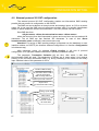
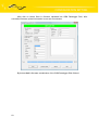
4.1. The basic configuration of the GSM Datalogger DA4.....................................................53
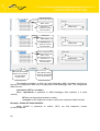
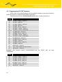
4.2. External protocol XC-CNT configuration.........................................................................57
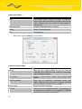
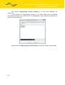
4.3. GSM Datalogger DA4 monitoring...................................................................................59
4.4. Upload firmware to GSM Datalogger DA4......................................................................61
4.5. Programming XC-CNT firmware.....................................................................................64
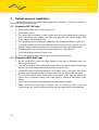
5.OPTICAL SENSORS INSTALLATION...................................................................................66
5.1. Flowmeter WP, WS type.................................................................................................66
5.2. Flowmeter WPD type......................................................................................................66
6.REFERENCES.......................................................................................................................67
7.LINKS TO RELATED PRODUCTS OF THE MANUFACTURER...........................................67
7.1. Systems..........................................................................................................................67
7.2. Protocols.........................................................................................................................67
7.3. Software..........................................................................................................................67
7.4. Products..........................................................................................................................67
8.PRODUCT DISPOSAL INSTRUCTIONS...............................................................................68
9.COMPLAINTS PROCEDURE................................................................................................69
10.WARRANTY.........................................................................................................................71
Symbols used
Danger – important notice, which may have an influence on the user’s safety or the function
of the device.
Attention – notice on possible problems, which can arise to in specific cases.
Information, notice – information, which contains useful advices or special interest.
Conel limited, Sokolska 71, 562 04 Usti nad Orlici, Czech Republic
Issue in CZ, 22/01/09
3
SAFETY INSTRUCTIONS
1.
Safety instructions
Please observe the following safety instructions:
•
The GSM Datalogger DA4 must be used in compliance with all applicable international
and national laws and in compliance with any special restrictions regulating
the utilization of the communication module in prescribed applications
and environments .
•
Use only the original Conel company accessories. Thus you will prevent possible health
risks and damage to the devices and ensure compliance with all relevant provisions.
Unauthorised adjustments or use of unapproved accessories may result in damage to
the GSM Datalogger DA4 and breach of applicable laws. Use of unapproved adjustments
or accessories may lead to cancellation of guarantee, which has no effects on your legal
rights.
•
You are not allowed to open the GSM Datalogger DA4. Only SIM-card replacement
is allowed.
•
Caution! The SIM card could be swallowed by small children .
•
Voltage on the GSM Datalogger DA4 supply connector shall not be exceeded.
•
Caution! Do not connect power supply connector to the port connector PORT1 or PORT2,
it could be damage this ports.
•
Do not expose the GSM Datalogger DA4 to extreme conditions. Protect it from dust,
moisture and heat.
•
It is recommended not to use the GSM Datalogger DA4 at petrol stations. We remind
users to observe the limitations of radio devices use at pump stations, chemical plants
or where explosives are being used.
•
Switch the GSM Datalogger DA4 off in a air plane. Use of the GSM Datalogger DA4 may
endanger plane’s functions, interfere with mobile network and be illegal. By not following
these instructions the customer risks cancellation or termination of telephone services,
prosecution or both.
•
You have to be extremely careful when using the GSM Datalogger DA4 in proximity
to medical devices, such as pacemakers or hearing aids.
•
Close to TV sets, radios and PCs the GSM Datalogger DA4 may cause interference.
•
It is recommended to create proper copy or backup of all the important settings saved
in the device’s memory.
4
GSM DATALOGGER DESCRIPTION
2.
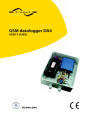
Description of the GSM Datalogger DA4
2.1. General
Telemetric arrangement GSM Datalogger DA4 is low power arrangement for gathering
in premises and objects, where reticular power supply isn't accessible. It is possible him easily
put through with control centre, where it is possible adjust characteristics, switch GSM
Datalogger DA to the online mode or also observe state of given object.
The GSM Datalogger DA4 sends messages about technology status and log history
in setting time. With dispatching or next equipment the DA4 communicates by inbuilt MC39i
modem of the SIEMENS company with GSM–GPRS choice or SMS mode. The GSM
Datalogger DA4 sends warning messages at time, for example: at settings limits overrun –
flow overrun etc. In case that it isn't data to send, the GSM Datalogger DA4 is in sleep mode,
this is easy in term of battery energy saving.
GSM Datalogger DA4 is a wireless data transmission device. The GSM Datalogger
DA4 is one of the basic elements of AGNES GPRS system. The system AGNES
characteristics are described in reference [1]. GSM-GPRS infrastructure is used for
the wireless communication as a line layer. ARNEP protocol is implemented above the line
layer. The protocol ARNEP is described in reference [2]. On its basis the modules create
virtual private data network where data can be transferred between user devices via any
protocols.
One may simply imagine the GSM Datalogger DA4 as a protocol converter between
the user device (PLC automatic, PC, data terminal, etc.) and GSM-GPRS infrastructure
of a mobile network operator. In fact the device is much more complicated, as it provides
the user with possibility to communicate simply between all the systems. Apart from data
transfers via GPRS the GSM Datalogger DA4 enables SMS.
The radio component GSM-GPRS is built in the GSM Datalogger DA4, consisting
of MC39i OEM module SIEMENS.
GSM Datalogger DA4 is controlled by communication 32-bit microprocessor. It ensures
GSM-GPRS communication, data transfer on serial user interfaces and a number of diagnostic
and service features. GSM Datalogger DA4 has one serial user interface (communication port)
RS232, one user interface for direct connection of inputs and outputs for data collection
and technological process management (communication port) CNT which processes data
and in sleep mode and one interface for direct connection of inputs and outputs (CIO)
which processes data in operate mode only. As a result you may communicate with various
user interfaces using different communication protocols on serial interface.
2.2. Examples of possible applications
The typical mounting of GSM datalogger can be:
•
•
•
•
•
•
•
5
Observation of pressure, flow, surface.
Isolator high tension.
Observation of statics construction.
Commentary from seismographs.
Metering of atmosphere cleanness.
Reading of several flow meters on one’s bus MBUS in housing houses
and in shafts with more flow meters.
Possibility to parameter setting or switch to the online mode from control centre.
GSM DATALOGGER DESCRIPTION
2.3. Compatibility with other Conel company modems
Regarding the communication and data transfers the GSM Datalogger DA4 is
compatible with the CGU 04i type and older CGU 04. This means it is possible to combine all
types in one network and simply extend an existing network of CGU 04i modules with new
communication points using GSM Datalogger DA4s. The GSM Datalogger DA4 provides some
features which is not included in the CGU 04i type.
User and industrial communication protocol implemented on serial interfaces are
compatible with the protocols used for Conel radio modems (e.g. CDA 70). You may establish
complex combined data networks consisting of radio, Ethernet and GPRS modems.
2.4. Description of GSM Datalogger DA4 components
2.4.1.
GSM module
SIEMENS MC39i OEM module is used for GSM network wireless communication. It is
integrated into printed circuit board. FME antenna connector is accessible from the back
panel. Release SIM card reader is located on the front panel.
The MC39i module communicates in three GSM bands (900 MHz, 1800 MHz
and 1900 MHz). It can transmit in two „Time Slots“ and receive in four (GPRS multi-slot class
10 – maximum reception bit speed 85.6 kb/s). It supports CS-1, CS-2, CS-3 and CS-4
encryptions).
2.4.2.
Control microprocessor
Thirty-two-bit microprocessor Freescale Coldfire with 1 MB SRAM backup memory,
512 kByte FLASH EEPROM memory and realtime circuit with reserve power supply makes
for the basis of GSM Datalogger DA4 control microprocessor. Software is based on realtime
operating system that processes simultaneous tasks. Thus parallel operation of all external
interfaces of the datalogger is maintained.
The microprocessor is connected through serial interface to MC39i OEM module
and controls the communication via GSM-GPRS. Towards a user it is connected on serial
interfaces RS 232 (PORT1), interfaces CNT (PORT2) for direct signals processing circuits,
and CIO interface.
6
GSM DATALOGGER DESCRIPTION
In case other than RS232 interface device needs to be connected, e.g. RS485/422, it is
possible to connect level converter to the serial port according to particular application.
The microprocessor can control such external converter.
The microprocessor further manages numerous functions of servicing, diagnostic
and installation purposes. Data transfer statistics, separate port communications, power
blackouts, voltage of the reserve supply, GSM Datalogger DA4 temperature and other
important information – everything is recorded in the microprocessor’s memory.
GSM Datalogger DA4 settings are saved in FLASH EEPROM memory. Service SW
RADWIN is designed for GSM Datalogger DA4 configuration. The description of programme
RADWIN is in reference [3].
2.4.3.
User interface protocols
There are numerous industrial protocols implemented on the PORT1 interface:
• ARNEP UI
• MBUS
• MODBUS
• transparent LINE
• AT modem
• SAUTER
• IWKA
• SBUS
• RADOM
• RDS CONEL
On the PORT2 interface are implemented protocols:
• XC-CNT/RDS92
• XC-CNT/MODBUS RTU master
• XC-CNT/MODBUS RTU slave
• XC-CNT/IEC 60870-5-104
• XC-CNT/myIO
• XC-CNT/SMS
New protocols, not supported by the datalogger yet, can be implemented according to
the customer’s needs. GSM Datalogger DA4 also enables the implementation of own user
protocol directly by the customer.
2.4.4.
Sleep mode
The GSM Datalogger DA4 contains voltage supply management. During idleness
the module GSM Datalogger DA4 is switched to sleep mode, when energy demand is very
slow (100 μA). Time of switch to sleep mode is adjustable. The status change on port or
control centre can wake up GSM Datalogger DA4 to on-line mode. The sleep mode isn't
possible to activate with service cable (data cable KD-2 and service jumper SEPRO).
7
GSM DATALOGGER DESCRIPTION
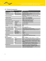
2.5. Technical parameters
GSM Datalogger DA4
Complies with
Power safety
standards
EMC
Radio parameters
SIEMENS MC39i
EN 60 950:2001
EN 55022:1998, A1:2000, A2:2003, Cor:2003
3GPP TS 51.010.-1,v5.5.0
EN 301 511, v7.0.1
Frequency bands
EGSM900, GSM1800 and GSM1900 (GSM
Phase 2/2+)
Transmit power
Class 4, 2 W for EGSM900
Class 1, 1 W for GSM1800
GPRS connection
GPRS multi-slot class 10 (4+2)
GPRS mobile station class B
Communication speed Transmission
2 x Time slot (max. 42.8 kb/s)
Reception
4 x Time slot (max. 85.6 kb/s)
Temperature range
Function
-20 oC to +55 oC
Storage
-40 oC to +85 oC
IP code
On the basic code IP20
Inside of switch box IP43
Power supply voltage Mains power supply +10 to +30 V DC
Battery
Accumulator 12 V/51 Ah
Lithium battery 8 x 3,6 V/16,5 Ah
and other types with nominal voltage 10-30 V
3.5 W
Consumption
GPRS TX
1W
GPRS on-line
350 mW
GSM stand-by
1 mW
Sleep mode
Dimensions
30 x 90 x 102 mm
(moulding fixed to DIN 35 mm slat)
Weight
150 g
Antenna connector
FME – 50 Ohm
User interfaces
PORT1
RS232 – connector RJ45 (300 b/s - 115 200
b/s)
PORT2
CNT – connector RJ45 - 2 counters, 2 binary
inputs, 2 analogy inputs, 1 binary output - open
collector
5 SW adjustable inputs (analogy, binary) /
CIO
outputs (open collector) – RJ45 connector
Operable time
According to numbers and type sensors,
numbers of measuring, exploitation of the
GPRS and according to quality of signal until 8
years out of battery change
8
GSM DATALOGGER DESCRIPTION
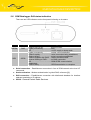
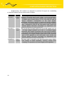
2.6. GSM Datalogger DA4 status indication
There are two LED indicators on the front panel informing on its status.
Colour
Description
GREEN
PWR
RED
GPRS
9
Meaning
Flashes once a sec…………...proper function
Lights permanently…………....fault
Off………………………….…....no DC supply or sleep mode
Lights permanently…………....neither serial established
Flashes rapidly…………….......serial connection being established,
Flashes slowly………………....serial connection established
Flashes together with PWR…..station activation failed
Inverse flashing to PWR……...no DNS connection
Off……………………….….......GSM GPRS communication
established
Flashes dimly……………..…...GPRS transmission or reception
●
Serial connection – Establishment connection in face of GSM network at the level AT
commands.
●
Station activation – Modem authentication in global DNS, reference [1].
●
DNS connection – Establishment connection with distributed database for interface
address translation to IP address.
●
GPRS – General Packet Radio Services.
GSM DATALOGGER DESCRIPTION
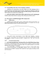
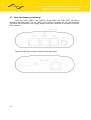
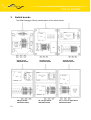
2.7. User interfaces (connectors)
There are RJ45 (PORT1 and PORT2), RJ12 (PWR) and FME (ANT) connectors
located on the back panel. The two PORT1 and PORT2 connectors are for user interfaces.
The fourth PWR connector is for supply adapter connection. Antenna is connected to the last
ANT connector.
There is RJ45 (CIO) connector located on the front panel.
10
GSM DATALOGGER DESCRIPTION
2.7.1.
PORT1 connector - RS232
Panel socket RJ45 (RS232 – DCE - Data Communication Equipment).
Pin
Signal
Description
number mark
1
RTS Request To Send
2
CTS Clear To Send
3
DTR Data Terminal Ready
4
DSR Data Set Ready – connected to +4 V through 330
Ohm
5
GND GROUND – signal ground
6
RXD Receive Data
7
CD Carrier Detect
8
TXD Transmit Data
Data flow
direction
Input
Output
Input
Output
Output
Output
Input
Circuit example of the meter with GSM Datalogger DA4:
Meter
11
GND
RXD
TXD
Pin 1 – RTS
Pin 2 – CTS
Pin 3 – DTR
Pin 4 – DSR
Pin 5 – GND
Pin 6 – RXD
Pin 7 – CD
Pin 8 – TXD
GSM Datalogger DA4
GSM DATALOGGER DESCRIPTION
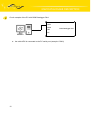
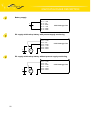
Circuit example of the PC with GSM Datalogger DA4:
PORT1
PORT2
Cable KD-2
PWR
GSM Datalogger DA4
ANT
●
12
the cable KD2 is connected to the PC serial port (example. COM1)
GSM DATALOGGER DESCRIPTION
2.7.2.
PORT2 connector - CNT
Panel socket RJ45
Pin number Signal mark
Description
Direction
1
BIN1/CNT1
Binary input/counter input
Input
2
BIN2/CNT2
Binary input/counter input
Input
3
BIN3
Binary input
Input
4
BIN4
Binary input
Input
5
GND
Signal ground
6
OUT1
Binary output (open collector)
Output
7
AN1
Analogy input
Input
8
AN2
Analogy input
Input
The user interface CNT is for monitoring and processing of analogy and binary signals
and to control (settings) of binary signal. To disposition are 2 counter and 2 binary inputs or 4
binary inputs, 2 analogy inputs a 1 binary output. The settings of binaries and counters inputs
by the help of firmware in which it is defined the singles inputs and output. The upload
firmware is in RADWIN program, see reference [3].
13
GSM DATALOGGER DESCRIPTION
2.7.2.1.
Analogy input
On analogy input it detected current, converted to digital 12-bits value and modified
by multiplicative and additive constant. Next the value is averaged on user settings and stored
to PC memory. The basic range of input current is 0 – 20 mA at input resistance 100 Ω.
Equal of value is:
12−bit. valueaddit.constant ∗multiplic. constant/1000
The sample period on analogy inputs is adjustable in range 0 ÷ 65535 seconds.
At value 0 it is sampling once per second and measurement circuit is permanent switch on.
At sampling it is possible to set time of measurement circuit switch from 16 ms to 375 ms.
On the basis of signal change about bigger value then setting upper/lower limit
is generated alarm. This alarm at defined settings of the GSM Datalogger DA4 generates
message with values of the all active signals and send it to defined target. The alarm end
is on the basis of bigger/lower signal change about set hysteresis than is upper/lower limit.
2.7.2.2.
Binary input
The binary input is potential-free contact which is 8 x per second sampling
and sampling time is 1/64 seconds. For binary inputs is possible to set active level either log. 0
or log. 1. Choice active level can generate alarm.
2.7.2.3.
Counter input
The counter inputs are meters maximal to 100 Hz. The ratio impulses on input can
be maximal 1:10, that means the impulse width mustn't be lower than 1/10 signal period.
At lower width it isn't guaranteed the true evaluation of the metered signal. For metering
of small frequencies (about mHz) it is important set the multiplicative constant which multiples
metering frequency (flow) because of true evaluation.
On the basis of signal change about bigger value then setting frequency upper limit
is generated alarm. Alarm is possible send after time after which upper limit must be overrun.
In case that it isn't any change on input, it is possible to define time after which
the value on input will zeroes.
2.7.2.4.
Binary output
The binary output is realized by transistor with open collector. In inactive state (log 0)
the transistor no transfer and is as switch off. In active state (log. 1) is transistor switch on and
connect signal on ground (GND).
Maximal switching current on output is 100 mA. Maximal voltage which can be
on transistor collector is power supply voltage of the GSM Datalogger DA4.
The impulse length is possible set in range 125 ÷ 8000 ms which is possible to send
on output after impulses number setting (1 ÷ 65535) on input BIN1/CNT1.
In sleep mode the all inputs and outputs values on PORT2 are metered and controlled.
14
GSM DATALOGGER DESCRIPTION
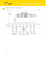
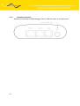
Typical connection of DA-4 measuring circuits
15
GSM DATALOGGER DESCRIPTION
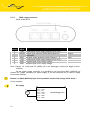
2.7.3.
PWR supply connector
Panel socket RJ45
Pin
number
Signal
mark
1
I/O 5
Input/Output – analogue or binary input or binary
output (open collector)
Input/Output
2
I/O 4
Input/Output – analogue or binary input or binary
output (open collector)
Input/Output
3
I/O 3
Input/Output – analogue or binary input or binary
output (open collector)
Input/Output
4
+12V
Output + 12V supply of other circuits (connected
directly to datalogger supply)
Output
5
GND
Signal and supply ground
6
I/O 2
Input/Output – analogue or binary input or binary
output (open collector)
Input/Output
7
I/O 1
Input/Output – analogue or binary input or binary
output (open collector)
Input/Output
8
Description
Service For servicing purposes only
Direction
Input/Output
GSM Datalogger DA4 is equipped with user interface CIO for analogue signal reception
and processing and control (settings) of binary signals. User is provided with 5 adjustable
inputs/outputs located on CIO connector at the front panel.
There are five signals linked to CIO that are possible to process and control by setting
up GSM Datalogger DA4. These signals can be controlled remotely, or their values can be
sent in data form to a remote point of data network.
16
GSM DATALOGGER DESCRIPTION
2.7.3.1.
Analogy input
Voltage is checked every 100 ms from the analogue input, transferred to digital ten-bit
value and adjusted by calibration constant. The value is further average-computed according
to user interface and saved in the computer memory. Basic input voltage range is 0 - 5 V.
Beware, in sleep mode the inputs values aren't measuring!
2.7.3.2.
Binary output
Binary output is implemented by a transistor with open collector connected to I/O
signal. When inactive (log 0) the transistor does not conduct and acts like open switch. When
active (log 1) the transistor acts like switch connecting I/O signal to the ground (GND). In both
cases the I/O value is measured as an analogue input. The status of switched circuit is being
checked.
Maximum switched output current is 500mA. Maximum voltage at transistor collector
equals the supply voltage of GSM Datalogger DA4.
Beware, in sleep mode the inputs values aren't measuring!
2.7.3.3.
Output signal for disconnection of supply voltage
The only single-output signal is PWRSV (Power Save). The signal is linked
to the supply connector (see the supply connector description). It is connected as universal I/O
signal outputs. This is an open collector that switches PWRSV signal to the ground (GND).
The output is controlled by a report similar to I/O outputs.
In general this output can be used to control technology.
2.7.3.4.
●
GSM Datalogger DA4 signals measuring
Measuring the supply voltage
Another two signals are measured in GSM Datalogger DA4. The first is called +UN (DC
SUPLY), it is an internal one and describes supply voltage on GSM Datalogger DA4 brackets.
The measuring range is 0 to 30 V. The supply voltage value has an effect over GSM
Datalogger DA4 function – in case it falls below the set value the GSM datalogger is
disconnected, because its proper function is not safeguarded, and discharge current
of reserve accumulator is reduced.
The second one is INAC (AC SUPLY) linked to the supply connector (see the supply
connector description). The measuring range is 0 to 30 V. The signal is protected against
overvoltage by a protection element that blocks voltage in excess of 33 V. INAC is designed
for measuring of network supply voltage presence. The change of the value is recorded
in GSM Datalogger DA4 statistics as a failure and rise of supply voltage 230 V.
Beware – it is impossible to link 230 v supply voltage directly to the input!
17
GSM DATALOGGER DESCRIPTION
●
Measuring internal GSM Datalogger DA4 temperature
To ascertain proper GSM module function, temperature is measured inside GSM
Datalogger DA4. In case the temperature exceeds the set control value, the GSM module is
disconnected from the supply voltage, as proper function is not guaranteed over this
temperature and at the same time it is protected against heat damage.
●
Measuring DSR output signal level
DSR signals on separate user interfaces are output signals from GSM Datalogger DA4
viewpoint. They are not controlled form the inside. Individual signals are linked through 330
Ohm resistors.
2.7.3.5.
Signal
name
Measuring
range [V]
I/O1-5
0 to 5
2.7.3.6.
●
I/O signals parameters
Resolution Sampling
[bit]
[ms]
10
100
Average
from
samples
Hysteresis
Control level
Optional
1 – 128
Optional
0 – 255
Optional
Settings CIO parameters
Activation of CIO signals
All CIO signals have an activity feature. In case a signal is active, its value is recorded
in CIO status report. Only when the active signal changes CIO may automatically generate
a corresponding report. In case a signal is not set as active, no matter how big a change it will
not generate change feature.
●
CIO communication parameters
The CIO block works in any GSM Datalogger DA4 independently from user interface
settings. CIO communication parameters settings decide whether the information
on measured signal values will be sent to a remote user interface.
Regarding communication, the CIO block operates in two modes: passive or active.
When passive, the CIO sends measured information only at the request of remote station.
When active, the reports are generated on the basis of changes of measured active signals
or on regular basis according to the period set.
The method of requesting CIO values is described in ARNEP protocol.
2.7.3.7.
Connecting CIO signals to user device
It is not appropriate and often even possible to connect I/O interface signals directly
to the user device. In order to measure currents, resistance and large voltage it is necessary
to mount series of circuits before I/O signals that will adjust the values measured to a voltage
within 0 to 5 V range and at the same time protect the inputs from interference
and overvoltage. Similarly serial electric circuits should be mounted to control power parts
of the user device, as the transistor with open collector is able to switch current up to 500 mA
and voltage up to the value of GSM Datalogger DA4 supply voltage.
18
GSM DATALOGGER DESCRIPTION
Supplementary CIO modules are designed for practical I/O signal use, establishing
an interface between the user device and I/O signals.
Name
CIO ANI 2
Type
Description
Analogue Analogue differential input for small voltage, current and resistance
input
measuring It includes differential amplifier with adjustable power
1 to 10000. Exact current source 0.1 to 3 mA can be used to
measure resistance. Configuration of the input signals,
amplification and current source is carried out through resistance
net. Presence of the input signal relevant to A/D converter working
range is signalled by LED on the front panel. Input circuits are
protected against short-time overvoltage by suppressors and
against the long-time one by reverse fuse.
CIO OPI 2
Binary
input
One galvanically-separated digital input for AC/DC signals up to 30
V, on high voltage brackets up to 350 V. It includes bipolar
optoelement that enables processing both input signal polarities.
For AC signal it includes integration circuit that provides for direct
processing of 50 Hz signal. Output logical value of the measured
signal is LED signalled on the front panel. Input circuits are
protected against short-time overvoltage by suppressors and
against the long-time one by a reverse fuse.
CIO REO 2
Binary
output
One relay output. It includes a relay with one switch contact. Switch
on/off contact is linked separately, common contact twice
(C marking). The presence of a control signal is LED signalled.
19
GSM DATALOGGER DESCRIPTION
Circuit example:
The modules CIO 2 are connects by the help of KD-51 cable (cable 1:1).
The connector K1 is input, K2 output to other CIO 2 module. By serial modems connection
the addresses are automatically assigned. In the direction from modem the addresses raises
uplink: 1,2,3,4 and 5. Maximal module number in series is five. See reference [4].
AC/DC 3-30V {
I1
I2
K1
K2
CIO 2 OpI
binary
input
1
2
4-climp
resistor
metering
{
CIO 2 AnI
analogy
input
NO
C
K1
K2
CIO 2 ReO
relay
output
Break contact {
20
NC
C
CIO
GSM Datalogger DA4
Cable KD-51
K1
K2
3
4
Switching contact {
Cable KD-51
Cable KD-51
GSM DATALOGGER DESCRIPTION
2.7.4.
PWR supply connector
Panel socket RJ12
Pin
Signal
Description
number mark
1
+UN
Positive pole of DC supply voltage (10 to 30 V)
2
PWRSV Output open collector (Power Save) See CIO
description
3
INAC Network supply presence check. Range 0 – V
4
+UN
Positive pole of DC supply voltage (10 to 30 V)
5
GND Negative pole of DC supply voltage
6
GND Negative pole of DC supply voltage
Direction
Output
Input
Note: Clamps 1-4 (+UN) and 5-6 (GND) are in the datalogger connect for bigger current
overload.
On the power supply connector it is possible to use the signal INAC (NAP230) for
present AC voltage monitoring for power supply (it can be functional only in case of supply
accumulator backup).
Beware, on INAC (NAP230) input it isn't possible connect link voltage 230 V direct !
Circuit example:
DC supply
+
DC
21
Pin 1 – +UN
Pin 2 – NC
Pin 3 – INAC
Pin 4 – +UN
Pin 5 – GND
Pin 6 – GND
GSM Datalogger DA4
GSM DATALOGGER DESCRIPTION
Battery supply
+
Pin 1 – +UN
Pin 2 – NC
Pin 3 – INAC
Pin 4 – +UN
Pin 5 – GND
Pin 6 – GND
GSM Datalogger DA4
DC supply with backup battery with present supply monitoring
+
Pin 1 – +UN
Pin 2 – NC
Pin 3 – INAC
Pin 4 – +UN
Pin 5 – GND
Pin 6 – GND
+
GSM Datalogger DA4
DC
DC supply with backup battery without present supply monitoring
+
22
+
DC
Pin 1 – +UN
Pin 2 – NC
Pin 3 – INAC
Pin 4 – +UN
Pin 5 – GND
Pin 6 – GND
GSM Datalogger DA4
GSM DATALOGGER DESCRIPTION
2.7.5.
Antenna connection
Antenna is connected to GSM Datalogger DA4 by FME connector on the back panel.
23
GSM DATALOGGER DESCRIPTION
2.8. Technical specifications of port 2
●
PORT1 with RS232 serial link
Name of product
Power supply
Environment
Standards
Bus RS232
(EN 1434)
●
Expansion port RS232
Internal
Operating temperature
Storage temperature
Emission
Immunity
Safety
Max. operating bus current
Max. data rate
Max. overvoltage
Max. total cable length
(300Bd, 200nF/km)
PORT2 with direct connected CNT users signals
Name of product
Power supply
Supply power
Environment
Standards
Inputs/outputs
Expansion port CNT
Voltage
Sleep
Operation
Operating temperature
Storage temperature
Emission
Immunity
Safety
Isolation
2x counter
2x analogy inputs
Others
24
...
-20 .. +55 C
-20 .. +85 C
EN 55022/B
ETS 300 342
EN 60950
15 mA
230400 bps
±30 V
20 m
2x binary inputs
1x output (open collector)
Voltage resistance
Sleeping mode
Internal 10 .. 30V
100 µA (counter is
functional)
2 mA
-20 .. +55 C
-20 .. +85 C
EN 55022/B
ETS 300 342
EN 60950
EN 60747
Max. 100 Hz,
ratio max. 1:10
0 .. 20 mA,
Rin 100 Ohms
reed contact
100 mA
Permanent
Controlled
GSM DATALOGGER DESCRIPTION
2.9. GSM Datalogger DA4 settings
Configuration and service SW RADWIN is designed for the datalogger setup (reference
[3]). The software is created for MS WINDOWS 95/98/ME/2000/XP platforms. Service cable is
designed for GSM Datalogger DA4 connection. After service cable (data cable KD-2 and jump
service SEPRO) is connected to any serial user interface RS232 and service SW runs
on a connected PC it is possible to execute not just all the needed GSM Datalogger DA4
settings, but service interventions in the data network as well.
Data cable KD-2
GSM Datalogger DA4 settings can be done remotely via GPRS. Remote configuration
access is protected by password. The enter password it is possible only after straight connect
by service cable.
2.10. Service cable
GSM Datalogger DA4 – PC connection cable with DCR and GND signals connected at
100 Ohm. It is made from normal data cable KD-2 by adding service interconnection SEPRO.
It is necessary to interconnect all eight signals between GSM Datalogger DA4 and PC. See
RJ45 connectors’ description in chapter 2.7.1.
Service interconnection SEPRO to the data cable
25
GSM DATALOGGER DESCRIPTION
2.11. XC-CNT protocol
To enable datalogger functionality must be selected protocol XC-CNT on interface
PORT 2. This protocol is used to read internal datalogger buffer of expander board XC-CNT.
Data is archived to backuped modem RAM, sending by one of implemented protocols
and control of main power supply in power management mode.
2.12. Available communication protocols
Using XC-CNT protocol parameter „RF channel protocol“ can be choosed a number
of communication protocols. List of protocols:
RDS92
●
data sending by message code 0x30
●
remote XC-CNT configuration
●
remote XC-CNT counters settings
●
digital output remote control
●
data logger reading, when power management is not active
●
maximum message length 2048 B (1000 B for GPRS)
MODBUS RTU master
●
data sending by message code 0x10 (write registers)
●
maximum message length 255 B
MODBUS RTU slave
●
data logger reading by message code 0x03 (read registers)
●
maximum message length 255 B
IEC 60870-5-104
●
data sending by telegrams type M_SP_TB_1, M_ME_TF_1 and M_IT_TB_1
●
telegrams processing type C_IC_NA_1 and C_CS_NA_1
●
outputs control by telegrams C_SC_NA_1 or C_SC_TA_1
●
data encapsuling into TCP or ARNEP
MyIO
●
data sending by HTTP protocol
●
remote XC-CNT configuration
●
digital output remote control
SMS
26
●
data sending by SMS
●
maximum message length 160 characters
GSM DATALOGGER DESCRIPTION
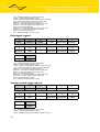
2.13. Recommended settings for testing
Parameter
Settings
Sleep mode
NO
Samples period storing
1 min
Wake-up period
0 min
Period between
communications
1 min
ANx – sample period
0 sec
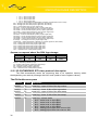
2.14. XC-CNT/RDS92 protocol description
The DA4 automatically sends all logs to dispatching by message with 0x30 code after
defined time (the DA4 logs request about storage). The dispatching confirms every logging
by message with 0x31 code (answer on request about the DA4 logs storage) in which it can
specify time, after which the DA4 will stay in receive yet. In case of need the dispatching have
possibility to send message with 0x06 code (data request) or 0x08 code (data logging request)
for snapping or the DA4 parameters set up.
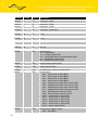
Request about the DA4 logs storage
27
1
1
2
1
1
1
Type
Address
Length
Code
PIN
RecLen
2
4
2
2
2
2
ID
Time
Alarms
DCVoltage
BIN
AN1
2
4
2
2
2
2
AN2
CNT1
CNT1FAct
CNT1FAvg
CNT1FMin
CNT1FMax
4
2
2
2
2
2
CNT2
CNT2FAct
CNT2FAvg
CNT2FMin
CNT2FMax
ACVoltage
2
2
2
2
2
2
Temperature
CIO1
CIO2
CIO3
CIO4
CIO5
8 to 54
8 to 54
...
1
2. log
3. log
...
Sum
GSM DATALOGGER DESCRIPTION
Type – RDS92 message type (1 byte). 0x44 always.
Address – station interface address (1 byte).
Length – RDS92 message data part length (2 bytes, lower first).
Code – request code about the DA4 logs storage (1 byte). 0x30 always.
PIN – packet identification number (1 byte).
RecLen – one log length (1 byte).
8 bytes – every log contents ID to Alarms array
16 bytes – every log contents ID to AN2 array
28 bytes – every log contents ID to CNT1FMax array
40 bytes – every log contents ID to CNT2FMax array
54 bytes – every log contents ID to CIO5 array
ID – log number (2 bytes, higher first).
Time – time stamp – seconds number from 1.1.1970 (4 bytes, higher first).
Alarms – alarms actual state bits array (2 bytes, higher first).
bit 0 – active level on input BIN1
bit 1 – active level on input BIN2
bit 2 – active level on input BIN3
bit 3 – active level on input BIN4
bit 4 – analogy input upper limit overrun AN1
bit 5 – analogy input lower limit overrun AN1
bit 6 – analogy input upper limit overrun AN2
bit 7 – analogy input lower limit overrun AN2
bit 8 – limit frequency overrun CNT1
bit 9 – limit frequency overrun CNT2
bit 10 – active level on input CIO1
bit 11 – active level on input CIO2
bit 12 – active level on input CIO3
bit 13 – active level on input CIO4
bit 14 – active level on input CIO5
bit 15 – power supply failure
DCVoltage – power supply in tens mV (2 bytes, higher first).
BIN – binary inputs states (2 bytes, higher first).
bit 0 – level on input BIN1
bit 1 – level on input BIN2
bit 2 – level on input BIN3
bit 3 – level on input BIN4
bit 6 – level on output BOUT1
bit 10 – level on input CIO1
bit 11 – level on input CIO2
bit 12 – level on input CIO3
bit 13 – level on input CIO4
bit 14 – level on input CIO5
bit 15 – value validity CIO (DCVoltage, ACVoltage, Temperature and CIO1 to CIO5)
AN1 – analogy input value AN1 (2 bytes, higher first, with marker).
AN2 – analogy input value AN2 (2 bytes, higher first, with marker).
CNT1 – counter status CNT1 (4 bytes, higher first).
CNT1FAct – counter actual frequency CNT1 (2 bytes, higher first).
CNT1FAvg – counter average frequency CNT1 (2 bytes, higher first).
CNT1FMin – counter minimal frequency CNT1 (2 bytes, higher first).
CNT1FMax – counter maximal frequency CNT1 (2 bytes, higher first).
CNT2 – counter status CNT2 (4 bytes, higher first).
CNT2FAct – counter actual frequency CNT2 (2 bytes, higher first).
CNT2FAvg – counter average frequency CNT2 (2 bytes, higher first).
CNT2FMin – counter minimal frequency CNT2 (2 bytes, higher first).
CNT2FMax – counter maximal frequency CNT2 (2 bytes, higher first).
ACVoltage – line voltage in tens mV (2 bytes, higher first).
Temperature – station temperature in decimals ºC (2 bytes, higher first, with marker).
CIO1 – analogy input value CIO1 (2 bytes, higher first).
CIO2 – analogy input value CIO2 (2 bytes, higher first).
CIO3 – analogy input value CIO3 (2 bytes, higher first).
CIO4 – analogy input value CIO4 (2 bytes, higher first).
CIO5 – analogy input value CIO5 (2 bytes, higher first).
Sum – RDS92 message check sum (1 byte).
28
GSM DATALOGGER DESCRIPTION
Answer on request about the DA4 logs storage
1
1
2
1
1
1
Type
Address
Length
Code
PIN
Time
1
Sum
Type – RDS92 message type (1 byte). 0x44 always.
Address – interface station address (1 byte).
Length – RDS92 message data part length (2 bytes, lower first). 0x03 always.
Code – confirmation code of the DA4 logs storage (1 byte). 0x31 always.
PIN – confirmations packet identification number (1 byte).
Time – seconds number after which the DA4 will stay in receive after confirmation receiving (1 byte).
Sum – RDS92 message check sum (1 byte).
Data request
1
1
2
1
2
2
Type
Address
Length
Code
2
...
2
2
...
1
BlockLen1
...
BlockAdrX
BlockLenX
...
Sum
2
2
BlockCount BlockAdr1
Type – RDS92 message type (1 byte). 0x44 always.
Address – interface station address (1 byte).
Length – RDS92 message data part length (2 bytes, lower first).
Code – data request code (1 byte). 0x06 always.
BlockCount – block number (2 bytes, higher first).
BlockAdr1 – first block start address (2 bytes, higher first).
BlockLen1 – first block length (2 bytes, higher first).
BlockAdrX – X-th block start address (2 bytes, higher first).
BlockLenX – X-th block length (2 bytes, higher first).
Sum – RDS92 message check sum (1 byte).
Answer on data request
29
1
1
2
1
Type
Address
Length
Code
2
N
...
2
2
N
BlockLen1
Data1
...
BlockAdrX
BlockLenX
DataX
...
1
...
Sum
BlockCount BlockAdr1
GSM DATALOGGER DESCRIPTION
Type – RDS92 message type (1 byte). 0x44 always.
Address – interface station address (1 byte).
Length – RDS92 message data part length (2 bytes, lower first).
Code – Data request answer code (1 byte). 0x07 always.
BlockCount – block number (2 bytes, higher first).
BlockAdr1 – first block start address (2 bytes, higher first).
BlockLen1 – first block length (2 bytes, higher first).
Data1 – first block data (N bytes).
BlockAdrX – X-th block start address (2 bytes, higher first).
BlockLenX – X-th block length (2 bytes, higher first).
DataX – X-th block length (N bytes).
Sum – RDS92 message check sum (1 byte).
Data loggin reguest
1
1
2
1
2
2
Type
Address
Length
Code
2
N
...
2
2
N
BlockLen1
Data1
...
BlockAdrX
BlockLenX
DataX
...
1
...
Sum
2
2
BlockCount BlockAdr1
Type – RDS92 message type (1 byte). 0x44 always.
Address – interface station address (1 byte).
Length – RDS92 message data part length (2 bytes, lower first).
Code – request code about data loggin (1 byte). 0x08 always.
BlockCount – block number (2 bytes, higher first).
BlockAdr1 – first block start address (2 bytes, higher first).
BlockLen1 – first block length (2 bytes, higher first).
Data1 – first block data (N bytes).
BlockAdrX – X-th block start address (2 bytes, higher first).
BlockLenX – X-th block length (2 bytes, higher first).
DataX – X-th block length (N bytes).
Sum – RDS92 message check sum (1 byte).
Answer on data loggin reguest
1
1
2
1
Type
Address
Length
Code
2
N
...
2
2
N
BlockLen1
Data1
...
BlockAdrX
BlockLenX
DataX
...
1
...
Sum
Type – RDS92 message type (1 byte). 0x44 always.
Address – interface station address (1 byte).
Length – RDS92 message data part length (2 bytes, lower first).
30
BlockCount BlockAdr1
GSM DATALOGGER DESCRIPTION
Code – request code about data loggin (1 byte). 0x09 always.
BlockCount – block number (2 bytes, higher first).
BlockAdr1 – first block start address (2 bytes, higher first).
BlockLen1 – first block length (2 bytes, higher first).
Data1 – first block data (N bytes).
BlockAdrX – X-th block start address (2 bytes, higher first).
BlockLenX – X-th block length (2 bytes, higher first).
DataX – X-th block length (N bytes).
Sum – RDS92 message check sum (1 byte).
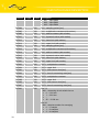
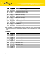
The DA4 addresses space
31
Address Length
Access Description
0x0200
1
-/W
binary output control
0x0500
4
-/W
counter status set up CNT1
0x0600
4
-/W
counter status set up CNT2
0x1000
4
R/-
actual log – ID
0x1004
4
R/-
actual log – Time
0x1008
2
R/-
actual log – Alarms
0x100A
2
R/-
actual log – DCVoltage *
0x100C
2
R/-
actual log – BIN *
0x100E
2
R/-
actual log – AN1
0x1010
2
R/-
actual log – AN2
0x1012
4
R/-
actual log – CNT1
0x1016
2
R/-
actual log – CNT1Freq
0x1018
2
R/-
actual log – CNT1FreqAvg
0x101A
2
R/-
actual log – CNT1FreqMin
0x101C
2
R/-
actual log – CNT1FreqMax
0x101E
4
R/-
actual log – CNT2
0x1022
2
R/-
actual log – CNT2Freq
0x1024
2
R/-
actual log – CNT2FreqAvg
0x1026
2
R/-
actual log – CNT2FreqMin
0x1028
2
R/-
actual log – CNT2FreqMax
0x102A
2
R/-
actual log – ACVoltage *
0x102C
2
R/-
actual log – Temperature *
0x102E
2
R/-
actual log – CIO1 *
0x1030
2
R/-
actual log – CIO2 *
GSM DATALOGGER DESCRIPTION
32
Address Length
Access Description
0x1032
2
R/-
actual log – CIO3 *
0x1034
2
R/-
actual log – CIO4 *
0x1036
2
R/-
actual log – CIO5 *
0x1038
8
R/-
actual log – reservation
0x1040
64
R/-
2. log
0x1080
64
R/-
3. log
...
...
...
...
0xEFC0
64
R/-
896. log
0xF000
1
R/W
sign bits array
bit 0 – sleep mode
bit 1 – send all values CIO
bit 2 – send SMS behind communication failure
bit 3 – send alarms status only
bit 4 – send alarm end at once
0xF001
2
R/W
sample storage period [min]
0xF003
2
R/W
wake up period [min]
0xF005
2
R/W
period between communications [min]
0xF007
2
R/W
permit alarms
• bit 0 – active level on input BIN1
• bit 1 – active level on input BIN2
• bit 2 – active level on input BIN3
• bit 3 – active level on input BIN4
• bit 4 – analogy input upper limit overrun AN1
• bit 5 – analogy input lower limit overrun AN1
• bit 6 – analogy input upper limit overrun AN2
• bit 7 – analogy input lower limit overrun AN2
• bit 8 – limit frequency overrun CNT1
• bit 9 – limit frequency overrun CNT2
• bit 10 – active level on input CIO1
• bit 11 – active level on input CIO2
• bit 12 – active level on input CIO3
• bit 13 – active level on input CIO4
• bit 14 – active level on input CIO5
• bit 15 – power supply failure
0xF009
1
R/W
binary inputs negative logical
• bit 0 – input BIN1
GSM DATALOGGER DESCRIPTION
Address Length
Access Description
•
•
•
bit 1 – input BIN2
bit 2 – input BIN3
bit 3 – input BIN4
0xF00A
2
R/W
AN1 - sampling period [sec]
0xF00C
2
R/W
AN1 - multiplicative constant (with marker)
0xF00E
2
R/W
AN1 - aditive constant (with marker)
0xF010
2
R/W
AN1 - hysteresis value (with marker)
0xF012
2
R/W
AN1 - lower limit (with marker)
0xF014
2
R/W
AN1 - upper limit (with marker)
0xF016
2
R/W
AN2 - sampling period [sec]
0xF018
2
R/W
AN2 - multiplicative constant (with marker)
0xF01A
2
R/W
AN2 - aditive constant (with marker)
0xF01C
2
R/W
AN2 - hysteresis value (with marker)
0xF01E
2
R/W
AN2 - lower limit (with marker)
0xF020
2
R/W
AN2 - upper limit (with marker)
0xF022
2
R/W
CNT1 - multiplicative constant
0xF024
2
R/W
CNT1 - upper limit
0xF026
2
R/W
CNT1 - limit overrun time [sec]
0xF028
1
R/W
CNT1 - time for measuring reset [sec]
0xF029
2
R/W
CNT2 - multiplicative constant
0xF02B
2
R/W
CNT2 - upper limit
0xF02D
2
R/W
CNT2 - limit overrun time [sec]
0xF02F
1
R/W
CNT2 - time for measuring reset [sec]
0xF030
1
R/W
bits 7-3:
AN1 - measuring circuit switch time on
• 0 → 1/64 sec
• 1 → 2/64 sec
• ...
• 30 → 31/64 sec
bits 2-0:
AN1 - samples number for averaging
• 0 → 1 sample
• 1 → 2 samples
• 2 → 4 samples
33
GSM DATALOGGER DESCRIPTION
Address Length
Access Description
•
•
0xF031
1
R/W
4 → 8 samples
5 → 16 samples
bits 7-3:
AN2 - measuring circuit switch time on
• 0 → 1/64 sec
• 1 → 2/64 sec
• ...
• 30 → 31/64 sec
bits 2-0:
AN2 - samples number for averaging
• 0 → 1 sample
• 1 → 2 samples
• 2 → 4 samples
• 4 → 8 samples
• 5 → 16 samples
0xF032
1
R/W
communication repeat period [min]
0xF033
1
R/W
data sending attempts number
0xF034
1
R/W
active mode time [min]
0xF035
1
R/W
quiescent level of binary outputs
• bit 0 – output OUT1
0xF036
2
R/W
dispenser – impulse number on input BIN1/CNT1
0xF038
1
R/W
dispenser – impulse lenght on output OUT1 [1/8 sec]
0xFF00
2
-/W
time on which the DA4 will stay on receiving yet
* CIO value validity is indicates by BIN array 15th bit.
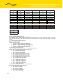
2.15. XC-CNT/MODBUS RTU master protocol description
The DA4 automatically sends all logs to dispatching by message 0x10 code (entry
values to more registers) after defined time and awaits appropriate confirmation
from dispatching.
DA4 logs storage request
34
1
1
2
2
1
2
Address
FC
RN
RC
BC
RecLen
GSM DATALOGGER DESCRIPTION
2
4
2
2
2
2
ID
Time
Alarms
DCVoltage
BIN
AN1
2
4
2
2
2
2
AN2
CNT1
CNT1FAct
CNT1FAvg
CNT1FMin
CNT1FMax
4
2
2
2
2
2
CNT2
CNT2FAct
CNT2FAvg
CNT2FMin
CNT2FMax
ACVoltage
2
2
2
2
2
40
Temperature
CIO1
CIO2
CIO3
CIO4
CIO5
2
CRC
Address – dispatching address (1 byte)
FC – function code (2 bytes, higher first). 0x10 always.
RN – referential number (2 bytes, higher first). It specifies the data space start in which the data are written. Every master
have dedicated space of the 256 registers where the first space register has number equal 256-multiple of the master
address.
RC – registers number (2 bytes, higher first).
BC – bytes number (1 bytes).
RecLen – log length (1 byte).
8 bytes – every log contents ID to Alarms array
16 bytes – every log contents ID to AN2 array
28 bytes – every log contents ID to CNT1FMax array
40 bytes – every log contents ID to CNT2FMax array
54 bytes – every log contents ID to CIO5 array
ID – log number (2 bytes, higher first).
Time – time stamp – seconds number from 1.1.1970 (4 bytes, higher first).
Alarms – alarms actual state bits array (2 bytes, higher first).
bit 0 – active level on input BIN1
bit 1 – active level on input BIN2
bit 2 – active level on input BIN3
bit 3 – active level on input BIN4
bit 4 – analogy input upper limit overrun AN1
bit 5 – analogy input lower limit overrun AN1
bit 6 – analogy input upper limit overrun AN2
bit 7 – analogy input lower limit overrun AN3
bit 8 – limit frequency overrun CNT1
bit 9 – limit frequency overrun CNT2
bit 10 – active level on input CIO1
bit 11 – active level on input CIO2
bit 12 – active level on input CIO3
bit 13 – active level on input CIO4
bit 14 – active level on input CIO5
bit 15 – power supply failure
DCVoltage – power supply in tens mV (2 bytes, higher first).
BIN – binary inputs states (2 bytes, higher first).
bit 0 – level on input BIN1
bit 1 – level on input BIN2
bit 2 – level on input BIN3
bit 3 – level on input BIN4
bit 6 – level on output BOUT1
bit 10 – level on input CIO1
35
GSM DATALOGGER DESCRIPTION
bit 11 – level on input CIO2
bit 12 – level on input CIO3
bit 13 – level on input CIO4
bit 14 – level on input CIO5
bit 15 – value validity CIO (DCVoltage, ACVoltage, Temperature a CIO1 to CIO5)
AN1 – analogy input value AN1 (2 bytes, higher first, with marker).
AN2 – analogy input value AN2 (2 bytes, higher first, with marker).
CNT1 – counter status CNT1 (4 bytes, higher first).
CNT1FAct – counter actual frequency CNT1 (2 bytes, higher first).
CNT1FAvg – counter average frequency CNT1 (2 bytes, higher first).
CNT1FMin – counter minimal frequency CNT1 (2 bytes, higher first).
CNT1FMax – counter maximal frequency CNT1 (2 bytes, higher first).
CNT2 – counter status CNT2 (4 bytes, higher first).
CNT2FAct – counter actual frequency CNT2 (2 bytes, higher first).
CNT2FAvg – counter average frequency CNT2 (2 bytes, higher first).
CNT2FMin – counter minimal frequency CNT2 (2 bytes, higher first).
CNT2FMax – counter maximal frequency CNT2 (2 bytes, higher first).
ACVoltage – line voltage in tens mV (2 bytes, higher first).
Temperature – station temperature in decimals ºC (2 bytes, higher first, with marker).
CIO1 – analogy input value CIO1 (2 bytes, higher first).
CIO2 – analogy input value CIO2 (2 bytes, higher first).
CIO3 – analogy input value CIO3 (2 bytes, higher first).
CIO4 – analogy input value CIO4 (2 bytes, higher first).
CIO5 – analogy input value CIO5 (2 bytes, higher first).
CRC – 16-bit check sum of data packet (2 bytes).
Answer on request about the DA4 logs storage
1
1
2
2
2
Address
FC
RN
RC
CRC
Address – dispatching address (1 byte)
FC – function code (2 bytes, higher first). 0X10 always.
RN – referential number (2 bytes, higher first).
RC – registers number (2 bytes, higher first).
CRC – 16-bit check sum of data packet (2 bytes).
2.16. XC-CNT/MODBUS RTU slave protocol description
The DA4 automatically stores the measuring data to its operation memory which
the dispatching can reads by message with 0x03 code (reads of more registers values).
The DA4 addresses space
36
Address
Access Description
0x1000
R/-
actual log – upper 16 bits of the log number
0x1001
R/-
actual log – lower 16 bits of the log number
0x1002
R/-
actual log – upper 16 bits of the time stamp
0x1003
R/-
actual log – lower 16 bits of the time stamp
0x1004
R/-
actual log – alarms status
• bit 0 – active level on input BIN1
• bit 1 – active level on input BIN2
• bit 2 – active level on input BIN3
• bit 3 – active level on input BIN4
• bit 4 – analogy input upper limit overrun AN1
• bit 5 – analogy input lower limit overrun AN1
GSM DATALOGGER DESCRIPTION
Address
Access Description
•
•
•
•
•
•
•
•
•
•
37
bit 6 – analogy input upper limit overrun AN2
bit 7 – analogy input lower limit overrun AN2
bit 8 – limit frequency overrun CNT1
bit 9 – limit frequency overrun CNT2
bit 10 – active level on input CIO1
bit 11 – active level on input CIO2
bit 12 – active level on input CIO3
bit 13 – active level on input CIO4
bit 14 – active level on input CIO5
bit 15 – power supply failure
0x1005
R/-
actual log – power supply in tens mV *
0x1006
R/-
actual log – binary inputs states
• bit 0 – input BIN1
• bit 1 – input BIN2
• bit 2 – input BIN3
• bit 3 – input BIN4
• bit 6 – level on output BOUT1
• bit 10 – level on input CIO1 *
• bit 11 – level on input CIO2 *
• bit 12 – level on input CIO3 *
• bit 13 – level on input CIO4 *
• bit 14 – level on input CIO5 *
• bit 15 – validity of CIO value
0x1007
R/-
actual log – precalculate value AN1 (with marker)
0x1008
R/-
actual log – precalculate value AN2 (with marker)
0x1009
R/-
actual log – upper 16 bits CNT1
0x100A
R/-
actual log – lower 16 bits
0x100B
R/-
actual log – actual frequency CNT1
0x100C
R/-
actual log – average frequency CNT1
0x100D
R/-
actual log – minimal frequency CNT1
0x100E
R/-
actual log – maximal frequency CNT1
0x100F
R/-
actual log – upper 16 bits CNT2
0x1010
R/-
actual log – lower 16 bits CNT2
0x1011
R/-
actual log – actual frequency CNT2
0x1012
R/-
actual log – average frequency CNT2
0x1013
R/-
actual log – minimal frequency CNT2
0x1014
R/-
actual log – maximal frequency CNT2
GSM DATALOGGER DESCRIPTION
Address
Access Description
0x1015
R/-
actual log – line voltage in tens mV *
0x1016
R/-
actual log – station temperature in decimals ºC *
0x1017
R/-
actual log – analogy input value CIO1 *
0x1018
R/-
actual log – analogy input value CIO2 *
0x1019
R/-
actual log – analogy input value CIO3 *
0x101A
R/-
actual log – analogy input value CIO4 *
0x101B
R/-
actual log – analogy input value CIO5 *
0x101C
R/-
actual log – reserve
0x101D
R/-
actual log – reserve
0x101E
R/-
actual log – reserve
0x101F
R/-
actual log – reserve
0x1020
R/-
2. log
0x1040
R/-
3. log
...
...
...
0xAFE0
R/-
1280. log
* CIO value validity is indicates by BIN array 15th bit.
38
GSM DATALOGGER DESCRIPTION
2.17. XC-CNT/IEC 60870-5-104 protocol description
The DA4 automatically sends all logs to dispatching in M_SP_TB_1, M_ME_TF_1
and M_IT_TB_1 types telegrams after connection established. The DA4 can work up received
commands C_IC_NA_1 (general inquiry), C_CS_NA_1 (time synchronization), C_SC_NA_1
(1-bit command without time) and C_SC_TA_1 (1-bit command with time).
Data points
39
IOA
Type
Description
101
M_SP_TB_1
alarm – active level on input BIN1
102
M_SP_TB_1
alarm – active level on input BIN2
103
M_SP_TB_1
alarm – active level on input BIN3
104
M_SP_TB_1
alarm – active level on input BIN4
105
M_SP_TB_1
alarm – analogy input upper limit overrun AN1
106
M_SP_TB_1
alarm – analogy input lower limit overrun AN1
107
M_SP_TB_1
alarm – analogy input upper limit overrun AN2
108
M_SP_TB_1
alarm – analogy input lower limit overrun AN2
109
M_SP_TB_1
alarm – limit frequency overrun CNT1
110
M_SP_TB_1
alarm – limit frequency overrun CNT2
201
M_SP_TB_1
input level BIN1
202
M_SP_TB_1
input level BIN2
203
M_SP_TB_1
input level BIN3
204
M_SP_TB_1
input level BIN4
301
M_ME_TF_1
analogy input value AN1
302
M_ME_TF_1
analogy input value AN2
401
M_IT_TB_1
counter status CNT1
402
M_IT_TB_1
counter status CNT2
411
M_ME_TF_1
counter actual frequency CNT1
412
M_ME_TF_1
counter actual frequency CNT2
421
M_ME_TF_1
counter average frequency CNT1
422
M_ME_TF_1
counter average frequency CNT2
431
M_ME_TF_1
counter minimal frequency CNT1
GSM DATALOGGER DESCRIPTION
IOA
Type
Description
432
M_ME_TF_1
counter minimal frequency CNT2
441
M_ME_TF_1
counter maximal frequency CNT1
442
M_ME_TF_1
counter maximal frequency CNT2
501
M_ME_TF_1
analogy input value CIO1
502
M_ME_TF_1
analogy input value CIO2
503
M_ME_TF_1
analogy input value CIO3
504
M_ME_TF_1
analogy input value CIO4
505
M_ME_TF_1
analogy input value CIO5
601
M_ME_TF_1
power supply [V]
602
M_ME_TF_1
link voltage [V]
603
M_ME_TF_1
station temperature [ºC]
Note.: The quantity of the send data points is depends on XC-CNT module firmware, alarms
permit of the singles inputs and parameters “send alarms status only” and “send all values
CIO”.
Commands
40
IOA
Type
Description
2201
C_SC_NA_1/
output control OUT1
C_SC_TA_1
2501
C_SC_NA_1/
output control CIO1
C_SC_TA_1
2502
C_SC_NA_1/
output control CIO2
C_SC_TA_1
2503
C_SC_NA_1/
output control CIO3
C_SC_TA_1
2504
C_SC_NA_1/
output control CIO4
C_SC_TA_1
2505
C_SC_NA_1/
output control CIO5
C_SC_TA_1
GSM DATALOGGER DESCRIPTION
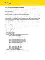
2.18. XC-CNT/myIO protocol description
The XC-CNT MyIO protocol is communications protocol of the XC-CNT firmware for
data transmition on web dispatching. By the help of this protocol the dispatching software
configures the module software, read her buffer, controls binary output and switches off main
station power supply.
The XC-CNT MyIO protocol is client/server type. It behaves as client which it connects
on dispatching server by the help of TCP connection in periodic time. As transport layer is
used HTTP protocol. Dispatching server has the static IP address.
The one communications relation has the following process: the client establish HTTP
connection on server and by the help of method POST it send all its data. Server receive data
and it send answer which it has up to 3 independent blocs: confirmation, output set up
and configuration. The compulsory is only confirmation block, other blocks the server sends
if it is need. In the end the client finish connection and it start count out time to next relation.
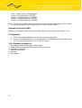
2.19. XC-CNT/SMS protocol description
The DA4 automatically sends all logs in SMS messages on telephone number after
defined time.
Outgoing SMS format
YYYY-MM-DD hh:mm:ss A=alarms V=voltage B1=bin B2=bin B3=bin B4=bin A1=analog
A2=analog C1=count,freqact,freqavg,freqmin,freqmax
C2=count,freq,freqavg,freqmin,freqmax
YYYY – year (1900-2036).
MM – month (01-12).
DD – day (01-31).
hh – hours (00-23).
mm – minutes (00-59).
ss – seconds (00-59).
alarms – alarms status in hexadecimal format (0000-FFFF).
bit 0 – active level on input BIN1
bit 1 – active level on input BIN2
bit 2 – active level on input BIN3
bit 3 – active level on input BIN4
bit 4 – analogy input upper limit overrun AN1
bit 5 – analogy input lower limit overrun AN1
bit 6 – analogy input upper limit overrun AN2
bit 7 – analogy input lower limit overrun AN2
bit 8 – limit frequency overrun CNT1
bit 9 – limit frequency overrun CNT2
bit 10 – active level on input CIO1
bit 11 – active level on input CIO2
bit 12 – active level on input CIO3
bit 13 – active level on input CIO4
bit 14 – active level on input CIO5
bit 15 – power supply failure
voltage – power supply in volts (0.00-21.45).
bin – binary input status (0-1).
analog – precalculate analogy input value (-32768 – 32767).
41
GSM DATALOGGER DESCRIPTION
count – counter status (0-4294967295).
freqact – actual frequency (0-65535).
freqavg – average frequency (0-65535).
freqmin – minimal frequency (0-65535).
freqmax – maximal frequency (0-65535).
Note.: The date, time, alarms status and power supply are sends in SMS always. Other values
are sends only if given input is supports by XC - CNT module firmware.
Example of the send SMS:
2006-01-16 09:15:40 A=0008 V=15.62 B1=1 B2=1 B3=0 A1=35 A2=3527 C1=12614,4,4,3,5
Configuration
●
GPRS connection establishing can disallow by entry empty APN.
●
In case of the SMS illegality on some telephones, it is possibility switch the SMS format
on 7-bit (only for firmware from 16.10.2007 and older)
2.20. Standard accessories
1.
2.
3.
4.
5.
6.
42
RJ12 supply connector for supply voltage cable.
Three RJ45 connectors for data cables and CIO connection.
Compliance certificate.
Complaint procedure.
Warranty.
User manual
GSM DATALOGGER DESCRIPTION
2.21. Additional accessories
1. Supply adapter
2. AO-DA4-PWRC supply cable
3. AO-AGSM-FME-V antenna
43
GSM DATALOGGER DESCRIPTION
2.22. Assembly procedure
GSM Datalogger DA4 is designed as a standard for:
1. Assembly to a panel using the through holes.
Through holes for montage
44
GSM DATALOGGER DESCRIPTION
2. DIN 35 mm rail assembly using plastic grips.
3. To be put on a worktop
45
GSM DATALOGGER DESCRIPTION
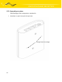
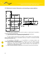
2.23. Mechanical external dimensions and mounting recommendations
For the majority of applications with a built-in modem in a switch board it is possible to
recognize two sorts of environments :
● non public and industry environment of low voltage with high interference,
● public environment of low voltage without high interference.
For both of these environments it is possible to mount modems to the switch board,
which it doesn't need to have no examination immunity or issues in connection with EMC
according to EN 60439-1+A1.
For compliance of EN 60439 - 1 + A1 specification it is necessary observe next
assembly of the modem to the switch - board:
● round antenna we recommend to observe a distance of 6 cm from cables and metal
surfaces on every side according to the next picture due to the elimination
of interference, while using an external antenna except for the switch-board it is
necessary to fit a lightening conductor,
● before mounting a modem on sheet-steel we recommend using an external antenna,
46
GSM DATALOGGER DESCRIPTION
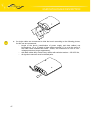
●
47
for single cables we recommend to bind the bunch according to the following picture,
for this use we recommend:
•
length of the bunch (combination of power supply and data cables) can
be maximum 1,5 m, if length of data cables exceeds 1,5 m or in the event of,
the cable leads towards the switch - board, we recommend to use fit over voltage protectors (surge suppressors),
•
with data cables they mustn't carry cables with reticular tension ~ 230 V/50 Hz,
•
all signals to sensors must be twisted pairs.
GSM DATALOGGER DESCRIPTION
48
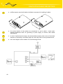
●
sufficient space must be left before individual connectors for handling of cables,
●
for correct function of the modem we recommend to use in switch - board earthbonding distribution frame for grounding of power supply of modem, data cables
and antenna,
●
in case of optical sensors usage, we recommended properly close covers of a sensors
because of overload by surrounding light, this case may result in wrong measurement,
●
the circuit diagram of the modem is on the following pictures.
GSM DATALOGGER DESCRIPTION
2.24. Product marking
G
S
Communications GSM-GPRS
M
Protocol MODBUS RTU
R
Protocol RDS 92
I
Protocol IEC 60870-5-104
X
Other – the customers specification
Communications GSM-SMS
S
Protocol SMS1
M
Serial interface M-BUS
V
HW interface inputs and outputs withs configuration
1a Input AN1 - analogue
1n Input AN1 - disabled
2a Input AN2 - analogue
2n Input AN2 - disabled
3b Input BIN1 - binary
3c Input BIN1 - counter
3d Input BIN1 + Input BIN2 – bidirectional counter
3n Input BIN1 - disabled
4b Input BIN2 - binary
4c Input BIN2 - counter
4d Input BIN1 + Input BIN2 – bidirectional counter
4n Input BIN2 - disabled
5b Input BIN3 - binary
5n Input BIN3 - disabled
6b Input BIN4 - binary
6n Input BIN4 - disabled
7o Output OUT1 - enabled
7d Output OUT1 - injector by counter at BIN1
7n Output OUT1 - disable
S
Basic mounting, IP20
Z
Pillar SIS 1h to field applications
R Small switch board IP54
L
Switching board IP54 on post or wall
V
Big switch board IP54
O Pb accumulator, eff. life min. 10 years, charging 2
years
L
Lithium battery, eff. Life 4 years for outdoor
applications
V Power supply from street lighting
N Power supply from LV (low voltage)
Examples: GMV-1n2n3c4n5n6n7o-SO or SSM-RL
49
GSM DATALOGGER DESCRIPTION
2.25. GSM Datalogger DA4 production label
2.26. Production label of interfaces PORT2
50
SWITCH BOARDS
3.
Switch boards
The GSM Datalogger DA4 is possible place to few switch boards.
R type board
205x220x140mm
ZN type board
205x319x118mm
51
VN type board
275x370x140mm
ZV, LV type board
205x319x118mm
VV type board
275x370x140mm
ZL, LL, ZO, LO type board
205x319x118mm
CONFIGURATION SETTING
4.
Configuration setting
Attention! If the SIM card isn’t included in the GSM Datalogger DA4, it is impossible
for the GSM Datalogger DA4 to operate. The Included SIM card must be activated for GPRS
transmissions. Insert the SIM card when the GSM Datalogger DA4 is switched off.
For monitoring of status, configuration and administration of the GSM Datalogger DA4
is RADWIN program [3]. In left top of the program window is main menu. In right under main
menu is function list which can do on GSM Datalogger. More informations is in help for this
program.
Main menu
Function list
Choice function
52
CONFIGURATION SETTING
4.1. The basic configuration of the GSM Datalogger DA4
The basic configuration is in Function list where it is choose function Configuration
(shortcut Ctrl + F1). After double click on parameter it is possible value change.
Protocol XC-CNT parameters description
Name
Value
Description
NA (HEX)/IA 1
Set network
address
Protocol
Name of the user's protocol (XC-CNT)
Port type
Modem port type information
Firmware type
Firmware type in XC-CNT module
Firmware configuration
Inputs and outputs configuration firmware
in XC-CNT module
Firmware version
YYYYMMDD
address
and
interface
Firmware version date in XC-CNT module
Communication protocol
Communicates protocol, which will send
or read data
Download configuration from server
After configuration set via web interface,
53
CONFIGURATION SETTING
target IP address set and this parameter
set the configuration will download from
server and upload to the DA4
RF channel acknowledge
YES, NO
Message
confirmation
on AGNEP protocol level
permitting
Send alarm termination
immediately
YES, NO
If it is alarm end, record will permitting to
send at once
Send only alarms
YES, NO
Permitting of the switch alarm on status
sending only
Send all CIO values
YES, NO
Permitting of the all measured CIO values
send (temperature, 2x voltage,
5x input analogy) in the each record (SMS
protocol out of own line)
Send actual data only
YES, NO
Permitting of actual data sending only
Target interface address
0 – 65534
Target modem address, on which
datalogger will send read data, or ASDU
address in protocol IEC 60870-5-104
Target IP address
xxx.xxx.xxx.xxx
The IP address of the server from which
DA4 configuration will download
TCP port
0 – 65535
TCP port of the IEC 60870-5-104 protocol
Phone number
12 point
number without
introductory +
Telephone number, where it will send
read data in case of SMS protocol choice
or
informative
SMS
in
case
of communication failed
Send SMS when communication
fail
YES, NO
Permitting of the “GPRS FAILURE” SMS
in case of communication failed (SMS
protocol out of own line)
Low power mode
YES, NO
Permitting of the switch sleep mode
on (XC-CNT
module
automatically
switches main power supply off)
Data sampling period
0 – 65535 min
Period, which XC-CNT module stores
samples to our buffer. After buffer
saturation it is switch main modem power
supply on short time and data are read
to redundancy RAM memory. If it is not
activate sleep mode, then data will read
continuously
Modem wake-up period
0 – 65535 min
Period, after which main power supply is
switch on by XC-CNT module. Parameter
will have mean, if it is need supplement
CIO values to measured samples
with defined period
Communications period
0 – 65535 min
Period, which the read data are send.
54
CONFIGURATION SETTING
Period isn't comply only in case that it is
record
new alarm, which it is send
at once
Retry communication period
0 – 255 min
Period, which the read data will resend,
if data aren't permit or it isn't exhaust
maximal attempt number
Max transmit retry
1–5
Maximal attempts number of the data
send to target modem
Online time
0 – 255 min
Time, which main modem power supply
will switch on
BINx – allow
YES, NO
Binary input permitting (according to
firmware
configuration
in
XC-CNT
module)
BINx – active level
Log1, Log0
Logical level, which it is signals alarm
BINx – alarm on active level
YES, NO
Permitting of alarm elicitation behind
active level
ANx – allow
YES, NO
Analogy input permitting (according to
firmware
configuration
in
XC-CNT
module)
ANx – sample period *
0 – 65535 sec
Input value sampling period. In case
of zero value, measuring circuit is switch
on permanently and input is samples
every
seconds. In case of non-zero
value, measuring circuit is switch on only
in defined time by following parameter
ANx – switch meas. circuit on time
*
16 – 375 msec
Measuring circuit switch on time and A/D
converter activation
ANx – sample number for
averaging
1 – 16
Samples number from which average
value is quantifies
ANx – multiplicative constant
1 – 65535
Calibration coefficient
ANx – additive constant
-32768 – 32767 Calibration coefficient
ANx – hysteresis
0 – 32000
ANx – lower limit
-32768 – 32767 Lower limit of signal alarm
ANx – upper limit
-32768 – 32767 Upper limit of signal alarm
ANx – lower limit overrun alarm
YES, NO
Permitting of the overrun limit alarm
invoking
ANx – upper limit overrun alarm
YES, NO
Permitting of the overrun limit alarm
invoking
CNTx – allow
YES, NO
Counter input permitting (according to
firmware
configuration
in
XC-CNT
55
Hysteresis
value
for
of the defined limits overrun
evaluation
CONFIGURATION SETTING
module)
CNTx – full duplex
YES, NO
Full duplex counter input permitting
(according to firmware configuration
in XC-CNT module)
CNTx – multiplicative constant
1 – 65535
Coefficient for flow calculation calibration
CNTx – flow upper limit
0 – 65535
Flow upper limit of signal alarm
CNTx – limit overrun time
0 – 65535 sec
Time after which must be overrun flow
upper limit to alarm signal
CNTx – time for measurement
reset
0 – 255 sec
Time after which will zero momentary
flow, if input status is unchanged
CNTx – upper limit overrun alarm
YES, NO
Permitting of the overrun limit alarm
invoking
OUT1 – enabled
YES, NO
Binary output permitting (according to
firmware
configuration
in
XC-CNT
module)
OUT1 – idle level
Log1, Log0
Logical level, to which is return output
after power supply failure
OUT1 – automatic feeder control
YES, NO
Automatic injector control permitting
(according to firmware configuration
in XC-CNT module)
OUT1 – number of impulses on
BIN1/CNT1
1 – 65535
Impulses number on BIN1/CNT1 input
after it is created impulse on output
OUT1 – impulse duration
0,125 – 8 sec
Created impulse length
CIOx – alarm on active level
YES, NO
Permitting of alarm elicitation behind
active level
PWR – alarm on active level
YES, NO
Permitting of alarm elicitation behind
active level
External configuration of protocol
Setting of sending information SMS, see
the chapter 3.2
* both XC-CNT module analogy inputs are sampling at once – it is use smaller from set
sample period and bigger from set measuring circuit switch time on.
56
CONFIGURATION SETTING
4.2. External protocol XC-CNT configuration
The external protocol XC-CNT configuration enables set informations SMS sending
parallel with set protocol in configuration on the PORT2.
The SMS are sent at alarms on binary/counter and analogy inputs, on CIO or at power
supply fail. It can send the SMS up to six telephone numbers when it is possible independent
define on which telephone number will send alarms. The every alarms can has a name.
Sent SMS has form:
<Object name> <Alarm issue/termination name> <Alarm name>
where the items are from itself separated by space and every item can has maximal 80
characters. The all SMS can has maximal 160 characters. In case of item Alarm
issue/termination name undefined is send alarm issue only.
Attention! For saving of SMS sending settings is important use the database or enter
interface address on PORT2 (the interface address configuration is in function Configuration
in Addresses tap).
After parameter select, for example Enable sending, in left part of protocol
configuration, is in right part editable field where is possible parameter editing.
The parameter Transmition limitation [s] set time, after which it wait than
the information SMS will send. This parameter is efficient set in cases when it isn't desired
sending of the few same information SMS, e.g. during oscillating of the switch on the binary
input. Maximal value of this parameter is 255 s.
Enable of SMS sending
Set of time which it wait
than the information
SMS message will send
Editable field
Define up to six tel. numbers
Object name
and issue/termination alarm
Analogy inputs alarm
Alarm name
Definition on
which tel. number
will send alarm
57
Editable field
CONFIGURATION SETTING
Counters inputs alarms
Alarm name
Definition on
which tel. number
will send alarm
Editable field
CIO alarms
Alarm name
Definition on
which tel. number
will send alarm
Editable field
Power supply alarms
Alarm name
Editable field
Definition on
which tel. number
will send alarm
After enter the interface
address it is possible
save all settings
by this button
After settings saving
is external configuration
finish by this button
The telephone numbers, on which are send information SMS, is possible configure by
the help of configuration SMS send on appropriate GSM Datalogger DA4. The configuration
SMS has form:
<password> SET<x> <number>
where: <password> is password to GSM Datalogger DA4 (implicitly it is serial
number),
SET<x> set appropriate telephone number,
<number> is new telephone number on which the information SMS will send.
Example: 123456 SET2 420123456789
where 123456
on 420123456789.
58
is
password
to
station,
SET2
set
2nd
telephone
number
CONFIGURATION SETTING
4.3. GSM Datalogger DA4 monitoring
In main menu Service item DA4 is possible see GSM Datalogger DA4 status.
This window has few parts:
59
●
Binary inputs – there is active inputs signalization, eventually alarm on active
level signalization.
●
Diagnostic – there is DC voltage status, in the case of power supply backup
AC voltage status and temperature inside modem.
●
Set output – possibility to switch on or switch off output, switch on or switch off
is signalized in information line in window bottom.
●
Analogy inputs – there are actual statuses on analogy inputs, in the case
of upper or lower limit overrun is can see alarm field.
CONFIGURATION SETTING
60
●
CIO – there is I/O signals status.
●
History – there are all last possible obtained statuses of the GSM Datalogger
DA4, at click on log it can see statuses of the inputs and outputs.
●
Counter inputs – there is counter state which after click on button Setting is
possible set (reset), flow, average flow, minimal and maximal flow, eventually
alarms at flow overrun.
●
Read new value – GSM Datalogger DA4 status is possible read only one shot
or cyclic. The period of read is set in Setting -> Properties -> Common tap ->
Rep. period.
●
Read history – pro find simplification of the GSM Datalogger DA4 status is
possible move in history after ten logs. By button First 10 is in panel History
ten the newest actual data. By button Next 10 is can see older data.
●
By button Configuration is possible basic configuration of the GSM Datalogger
DA4, see chapter 3.1.
●
By button Quit is the GSM Datalogger DA4 status and monitoring finished.
●
Information line – display informations
successful/unsuccessful data read and clock.
about
switch
on/switch
off,
CONFIGURATION SETTING
4.4. Upload firmware to GSM Datalogger DA4
The firmware actualization
in the GSM Datalogger DA4.
is
complex
function
which
do
program
update
The new firmware (files CGVL.bin and CGVM.bin) is necessary copy to directory BIN
in file where is installed RADWIN program in order to program RADWIN upload firmware into
GSM Datalogger DA4.
Attention! Do not switch off station power at firmware upload to station else the GSM
Datalogger DA4 can be damaged.
The function Upload firmware is in function list, see chapter 3.1.
In window for upload firmware are set values and properties for firmware upload.
In field File information is file name and date which is choose for upload into station. In field
Station information is firmware date in station before upload, station type and address
from them the firmware will upload. If in station is user created firmware then after date is
character (u). In field State and Progress are next diagnostic data. In part Total is can see
how long the upload is in progress.
61
CONFIGURATION SETTING
Button description
Button
Description
Start
Start firmware upload, version of firmware is compared.
In case, when station firmware is newest or same as file
in PC, dialogue give you chance to stop upload or
continue next
Start from origin
Complete overwrite firmware in station
Setting
Setting of firmware upload
Quit
Close dialogue
After click on button Setting is next window:
Parameters description
Parameter
Description
Source
Select file type, typically MAIN for main file with full
functionality and LOAD file with minimum functionality
(only for firmware upload)
Nr. of blocks
Number of block before Radwin send upload state
request
Confirm message
Select type of confirming. Unchecked means that
Radwin checked only at the end of upload, checked
means that Radwin checked every message
Block length
Number of bytes in message
Timeout
Timeout in ms for message delivery. If acknowledge is
not delivered in this timeout, error message is displayed
in dialogue and message is send again
62
CONFIGURATION SETTING
After click on button Start is firmware uploaded into GSM Datalogger DA4, after
successful firmware upload into station is can see next window:
By button Quit is firmware actualization of the GSM Datalogger DA4 finished.
63
CONFIGURATION SETTING
4.5. Programming XC-CNT firmware
PORT2 CNT of the GSM Datalogger DA4 is possible configure by the help of firmware,
which can activate or disactivate appropriate input/output.
Firmware name has form V1x2x3x4x5x6x7x.hex where number description is:
Pin
number
Description
1a
Input AN1 - analogy – switch on
1n
Input AN1 - switch off
2a
Input AN2 - analogy – switch on
2n
Input AN2 - switch off
3b
Input BIN1 - binary – switch on
3c
Input CNT1 - counter – switch on
3d
Input CNT1 + CNT2 – bidirect flow
3n
Input BIN1/CNT1 - switch off
4b
Input BIN2 - binary – switch on
4c
Input CNT2 - counter – switch on
4d
Input CNT1 + CNT2 – bidirect flow
4n
Input BIN2/CNT2 - switch off
5b
Input BIN3 - binary – switch on
5n
Input BIN3 - switch off
6b
Input BIN4 - binary – switch on
6n
Input BIN4 - switch off
7o
Output OUT1 – switch on
7d
OUT1, control feeder according to input 3
7n
Output OUT1 – switch off
Example: after firmware upload V1a2a3b4b5b6b7o.hex the PORT2 CNT will have
configuration:
Pin
number
64
Description
1a
Input AN1 - analogy – switch on
2a
Input AN2 - analogy – switch on
3b
Input BIN1 - binary – switch on
4b
Input BIN2 - binary – switch on
5b
Input BIN3 - binary – switch on
6b
Input BIN4 - binary – switch on
7o
Output OUT1 – switch on
CONFIGURATION SETTING
The function Programming XC-CNT firmware is in main menu Service, see
chapter 3.1.
In the window for programming firmware is by button File choice appropriate
configuration firmware for the PORT2 CNT. In field State are other diagnostic states with rail
where is programming time.
After successful Programming XC-CNT firmware is function finished by button Quit.
65
OPTICAL SENSORS INSTALLATION
5. Optical sensors installation
Optical sensor set to flowmeter Sensus (Meinecke or Spanner - Pollux) for scanning of
the IS2-12 flow by following way:
5.1. Flowmeter WP, WS type
1. Safety screw screw out in place of joint cover.
2. Gold cover uncover.
3. The cover frame lift slightly on side of joint cover and at the same time the frame is
turn to left when two tongues are free from bayonets pits on the bottom side
of the frame in the flowmeter body.
4. The optical sensor set to fishtail by cable down on transparent chassis of gear box.
5. The sensor cable one turn round bottom border of gear box and lead out by one
from two rough channels on body of the flow meter, on side of the safety screw.
6. Repeatedly the cover frame set to bayonet (attention on nip cable off).
7. Screw up the screw in place of joint cover.
8. The cover cover up back, herewith stop crossluminance to sensor.
5.2. Flowmeter WPD, WSD type
1. By the screw driver break out rough window on the side of flowmeter head, box
knife to get rid of burrs .
2. Turn the blue plastic collar, black head to the meter to the left to achieve that locking
knob on the collar outside the box for the sensor (right of him).
3. Infrasenzor attached oblique projections on its upper edge of the upper edge of the
box and meter enclose (back of the sensor down) into the right position to meter.
4. Turn the blue plastic collar, black head to the meter to the right will deliver the
sensor that is recessed locking collar meter fits into recess at the bottom of the
sensor.
5. The cover cover up back, herewith stop crossluminance to sensor.
6. When removing do everything in reverse order, ie. turning the collar on the left
trigger the sensor, the fork up and get away from the upper edge of the meter box.
66
REFERENCES AND LINKS
6. References
[1]
Conel s.r.o.: Application CGU Server, 2004
[2]
Conel s.r.o.: ARNEP Protocol description, 2005
[3]
Conel s.r.o.: RADWIN Programme for control AGNES, 2008
[4]
Conel s.r.o.: CIO 2 – Users manual, 2008
7. Links to related products of the manufacturer
Related products and materials with a reference can be found on the manufacturer’s
website – Conel company:
www.conel.cz
There are another links on Siemens company website, MC39i module:
www.siemens.de
www.siemens.com
7.1. Systems
AGNES – Advanced GPRS Network System – represents a solution for private
data network structures for industrial applications and technological systems.
7.2. Protocols
AGNEP – Advanced GPRS Network Protocol – one of the AGNES system
protocols.
7.3. Software
RADWIN – the software provides for creation, installation and administration
of AGNES system GPRS data networks.
7.4. Products
CGU 04 – GPRS modem.
CGU 04i – GPRS modem with sleep mode.
CGU Server – hardware and software equipment connecting AGNES system
and company LAN with the possibility of GPRS network control and diagnostics.
67
PRODUCT DISPOSAL
8. Product disposal instructions
The WEEE (Waste Electrical and Electronic Equipment: 2002/96/EC) directive has
been introduced to ensure that electrical/electronic products are recycled using the best
available recovery techniques to minimise the impact on the environment. This product
contains high quality materials and components which can be recycled. At the end of it’s life
this product MUST NOT be mixed with other commercial waste for disposal. Check with the
terms and conditions of your supplier for disposal information.
68
COMPLAINTS PROCEDURE
9. Complaints procedure
Dear customer,
The product you have purchased had passed manufacturer’s tests and its functions
had been checked by our technician before sale. In case any defect shows up during
the guarantee period that prevents normal use we ask you to follow the Complaints procedure
when registering your claim.
To make a possible complaint procedure easier please make sure when taking over
the product your vendor has duly filled in all the relevant parts of the warranty, including date,
seal and signature.
This complaints procedure relates to the purchased products. This complaints
procedure does not relate to the services provided.
Guarantee period of the products
Guarantee period of 24 months from the date of purchase is provided for the device,
source, antenna, data cable and possible accessories. The date of purchase is at the same
time date of takeover.
Registering a claim
It is necessary to register your claim at the vendor where the subject of the complaint
has been purchased. The customer shall present duly filled warranty and the complete subject
of the complaint. Subject of the complaint shall be presented in a condition adequate to that
at the moment of purchase.
Caution!
The vendor is not responsible for keeping default settings or data saved in the subject
of the complaint.
The customer is obliged to clarify the defect or how it is displayed and what claim
he intends to register.
Processing the complaint
The vendor shall provide a free remedy depending on particular conditions, or replace
the subject of the complaint for a new product, or settle the matter in another manner
in compliance with the Civil Code and the Act on consumer’s protection.
As of the moment the claim is registered by the customer and the subject
of the complaint is taken over by the vendor the guarantee period stops running.
The guarantee period continues on the date of takeover of the repaired subject
of the complaint or replaced faultless product by the customer, or should it not be taken over
on the date the customer is obliged to take over the repaired or replaced product. In case
the vendor replaces the subject of the complaint for a new product (including IMEI
replacement) the original subject of the complaint becomes property of the vendor
and the new product becomes property of the purchaser. Since takeover of the new product
a new guarantee period starts. In the cases when the vendor settles the matter after
agreement with the customer by replacement of the subject of the complaint for a faultless
product the new guarantee expires.
1. After 12 months since the replaced product was taken over by the customer.
69
COMPLAINTS PROCEDURE
2. On the date when the original guarantee period (subject of the complaint) would
have expired should it not have been replaced, whichever comes first.
3. The claim is deemed unsubstantiated when the defect is not found by the vendor
processing the complaint or the defect is not covered by the guarantee under
Article 3 of the procedure.
4. In case the claimed defect is not found and functionality is proven to the customer,
the customer is obliged to pay demonstrable cost related to expert assessment
of the claimed defect.
5. In case defect is found when processing the complaint that is not covered by
the guarantee (extra-warranty repair), the vendor shall inform the customer
and the customer shall inform the vendor whether he/she wishes to have the
defect repaired for the price set. A protocol shall be made on exact conditions
of the extra-warranty repair and signed by both the customer and the vendor.
Should the customer not require remedy through an extra-warranty repair under
the conditions, the device shall be returned to him/her after he/she pays
the demonstrable cost of expert assessment.
The guarantee does not cover defects incurred due to
1. Mechanical damage (fall and the like).
2. Use of inadequate, or not recommended sources and other accessories.
3. Connection of the product with non-standard accessories.
4. Installation or use of the product conflicting with the Manual or use for other
purposes than usual for this type.
5. Improper manipulation, or an intervention of unauthorised person or other service
than authorised by the manufacturer.
6. Effects of natural forces (flood, fire etc.) or other local phenomena (storm,
overvoltage and the like).
7. Storage under unauthorised temperatures.
8. Operation in a chemically aggressive environment.
Other conditions
The fact that the subject of the complaint does not conform to parameters set for other
similar product types shall not be considered a fault. To assess whether it is a case of covered
fault the parameters stated in the technical documentation for the product are decisive.
The guarantee expires in any case of changes to the subject of the complaint,
or damaged or otherwise unreadable serial number.
70
WARRANTY
10. Warranty
Device type
Serial number
Guarantee period (months)
Vendor
Date of purchase
Seal of the vendor
71
WARRANTY
1
Date of complaint
registration
Complaint
protocol number
Date of reception
of the device in
repair shop
Date of finished
repair
Number of repair
sheet
Warranty repair
New serial
number of the
device (IMEI)
Notes
Seal of the repair
shop
72
2
3
4
5