1
GSM DATALOGGER DESCRIPTION
2.7.4.
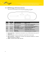
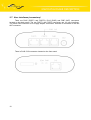
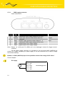
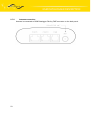
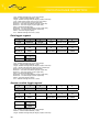
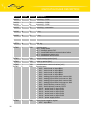
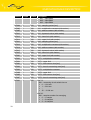
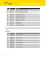
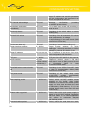
PWR supply connector
Panel socket RJ12
Pin
Signal
Description
number mark
1
+UN
Positive pole of DC supply voltage (10 to 30 V)
2
PWRSV Output open collector (Power Save) See CIO
description
3
INAC Network supply presence check. Range 0 – V
4
+UN
Positive pole of DC supply voltage (10 to 30 V)
5
GND Negative pole of DC supply voltage
6
GND Negative pole of DC supply voltage
Direction
Output
Input
Note: Clamps 1-4 (+UN) and 5-6 (GND) are in the datalogger connect for bigger current
overload.
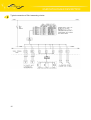
On the power supply connector it is possible to use the signal INAC (NAP230) for
present AC voltage monitoring for power supply (it can be functional only in case of supply
accumulator backup).
Beware, on INAC (NAP230) input it isn't possible connect link voltage 230 V direct !
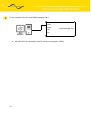
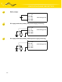
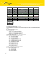
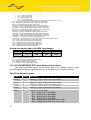
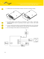
Circuit example:
DC supply
+
DC
21
Pin 1 – +UN
Pin 2 – NC
Pin 3 – INAC
Pin 4 – +UN
Pin 5 – GND
Pin 6 – GND
GSM Datalogger DA4