1
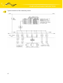
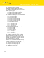
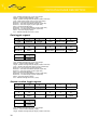
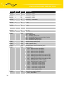
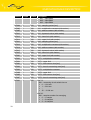
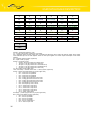
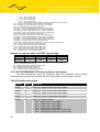
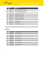
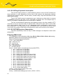
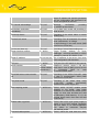
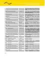
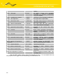
GSM DATALOGGER DESCRIPTION Type – RDS92 message type (1 byte). 0x44 always. Address – station interface address (1 byte). Length – RDS92 message data part length (2 bytes, lower first). Code – request code about the DA4 logs storage (1 byte). 0x30 always. PIN – packet identification number (1 byte). RecLen – one log length (1 byte). 8 bytes – every log contents ID to Alarms array 16 bytes – every log contents ID to AN2 array 28 bytes – every log contents ID to CNT1FMax array 40 bytes – every log contents ID to CNT2FMax array 54 bytes – every log contents ID to CIO5 array ID – log number (2 bytes, higher first). Time – time stamp – seconds number from 1.1.1970 (4 bytes, higher first). Alarms – alarms actual state bits array (2 bytes, higher first). bit 0 – active level on input BIN1 bit 1 – active level on input BIN2 bit 2 – active level on input BIN3 bit 3 – active level on input BIN4 bit 4 – analogy input upper limit overrun AN1 bit 5 – analogy input lower limit overrun AN1 bit 6 – analogy input upper limit overrun AN2 bit 7 – analogy input lower limit overrun AN2 bit 8 – limit frequency overrun CNT1 bit 9 – limit frequency overrun CNT2 bit 10 – active level on input CIO1 bit 11 – active level on input CIO2 bit 12 – active level on input CIO3 bit 13 – active level on input CIO4 bit 14 – active level on input CIO5 bit 15 – power supply failure DCVoltage – power supply in tens mV (2 bytes, higher first). BIN – binary inputs states (2 bytes, higher first). bit 0 – level on input BIN1 bit 1 – level on input BIN2 bit 2 – level on input BIN3 bit 3 – level on input BIN4 bit 6 – level on output BOUT1 bit 10 – level on input CIO1 bit 11 – level on input CIO2 bit 12 – level on input CIO3 bit 13 – level on input CIO4 bit 14 – level on input CIO5 bit 15 – value validity CIO (DCVoltage, ACVoltage, Temperature and CIO1 to CIO5) AN1 – analogy input value AN1 (2 bytes, higher first, with marker). AN2 – analogy input value AN2 (2 bytes, higher first, with marker). CNT1 – counter status CNT1 (4 bytes, higher first). CNT1FAct – counter actual frequency CNT1 (2 bytes, higher first). CNT1FAvg – counter average frequency CNT1 (2 bytes, higher first). CNT1FMin – counter minimal frequency CNT1 (2 bytes, higher first). CNT1FMax – counter maximal frequency CNT1 (2 bytes, higher first). CNT2 – counter status CNT2 (4 bytes, higher first). CNT2FAct – counter actual frequency CNT2 (2 bytes, higher first). CNT2FAvg – counter average frequency CNT2 (2 bytes, higher first). CNT2FMin – counter minimal frequency CNT2 (2 bytes, higher first). CNT2FMax – counter maximal frequency CNT2 (2 bytes, higher first). ACVoltage – line voltage in tens mV (2 bytes, higher first). Temperature – station temperature in decimals ºC (2 bytes, higher first, with marker). CIO1 – analogy input value CIO1 (2 bytes, higher first). CIO2 – analogy input value CIO2 (2 bytes, higher first). CIO3 – analogy input value CIO3 (2 bytes, higher first). CIO4 – analogy input value CIO4 (2 bytes, higher first). CIO5 – analogy input value CIO5 (2 bytes, higher first). Sum – RDS92 message check sum (1 byte). 28