1
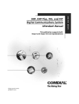
Installing the Bridged Console
Introducing the Bridged Console
You can bridge DSS/BLF console models IB24X and IB48X to model 8324F, 8324S, 8312S, and 8212S Impact
telephones. When you connect a DSS/BLF console to the bridged console port of these telephones, you are
actually connecting the console to the same physical station port as the telephone is connected. Taking this action
adds a console to the system without dedicating a physical station port for its installation. The controlling
software allows up to 16 of the IB24X or IB48X consoles to a system.
In the bridged mode, the console requires external power applied by an AC wall transformer assembly. An
exception to this requirement is at installations that also have the IMIST device installed in the host telephone’s
adjustable pedestal. With those installations, the AC wall transformer assembly for the IMIST device also
supplies power for the bridged console through wiring internal to the telephone. Conversely, the AC wall
transformer assembly for the bridged console arrangement will also supply power for the IMIST device if you
wish to make that arrangement instead. Either way, you need only one AC wall transformer assembly to power
both features when you install them both on the same host telephone.
Bridged console operation is fully functional with the FX Series systems equipped with an expanded digital
station board (FXLDS).
To support bridged console operation DXP and DXP Plus systems must conform to the following common
equipment configurations:
Common Equipment Requirements to Make Bridged Console Feature Functional
DXP
•
•
•
Requires 13A software (Systems with software
releases before 10A requires the DXPSW-DLRP
assembly that consists of 13A software plus a
DXRAM-EXPC memory board.)
DXP Plus
•
•
Requires 13A software
•
•
•
Requires DXCPU-PLS revision F board
Requires DXCPU-68K revision E board
Requires DXDLT revision A board
Assumes installed DXPSW-PLS4 RAM card
(DXPSW-PLS2 RAM cards will support 13A
software but available SMDR records decrease to
200)
Requires DXINT-PLSM1 revision C board
Requires DXDLT revision A board
The bridged console feature is not functional with the DSU and DSU II common equipment cabinets.
This manual has been developed by Comdial Corporation (the “Company”) and is intended for the use of its customers and service personnel. The information in this manual is subject to change
without notice. While every effort has been made to eliminate errors, the Company disclaims liability for any difficulties arising from the interpretation of the information contained herein.
The information contained herein does not purport to cover all details or variations in equipment or to provide for every possible contingency to be met in connection with installation, operation, or
maintenance. Should further information be desired, or should particular problems arise which are not covered sufficiently for the purchaser’s purposes, contact Comdial, Inside Sales Department,
Charlottesville, Virginia 22906.
Printed in U.S.A.
IMI89–283.02
1/00
IMI89–283
Installing the Bridged Console
Installing the Bridged Console
Use the installation kit (product code: IBKIT) to bridge the console to its host Impact telephone. The IBKIT
contains the following items:
•
•
6-conductor line cord,
AC wall transformer assembly.
To bridge the DSS/BLF console to the host Impact telephone,
1. Disconnect the host telephone from the common equipment cabinet.
2. Thread one end of the kit-supplied, 6-conductor line cord through the same opening in the telephone’s
adjustable pedestal that accommodates the telephone’s existing line cord. Mate the 6-conductor line cord’s
connector to the Bridged Console jack on the host telephone.
3. Connect the other end of the kit-supplied, 6-conductor line cord to Bridged Console jack on the underside of
the DSS/BLF console housing.
4. Unless the host telephone already includes an IMIST device in its adjustable pedestal, which includes its
own AC wall transformer assembly, you must connect the kit-supplied AC wall transformer to the DSS/BLF
console’s power jack.
5. Reconnect the host telephone to the common equipment cabinet, connect the AC wall transformer to the AC
power receptacle, take the necessary programming steps to enable bridged console operation, and test the
installation for proper operation.
Bridged Console
(IB48X Shown for example)
Typical Impact Telephone
(8324S-xx shown for example)
IB48X-XX
!
AC Wall
Transformer
Assembly
6-Conductor
Line Cord
!
jack1.cdr
Installing The Bridged Console
2 – Installing the Bridged Console
Installing the Bridged Console
IMI89–283
Programming for Bridged Console Operation
Once you have completed the installation and connected all necessary wiring, use VMMI programming to enable
the bridged console operation. Do this from the following menu: Stations/Station Programming/Options1.
From this programming menu, bridge Impact DSS/BLF console models IB24X and IB48Xs to Impact telephone
models 8324F, 8324S, 8312S, and 8212S.
To enable bridged console operation, the system must be equipped with an expanded digital station board
(FXLDS boards for FX systems, or DXDLT revision A boards for DXP and DXP Plus systems) to support the
host telephone. After you install the expanded digital station board, you must assign it to the system using the
Board Configuration programming menu.
Programming for Bridged Console Operation – 3
R
Charlottesville, Virginia 22901-2829
World Wide Web: http://www.comdial.com/