1
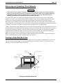
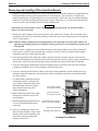
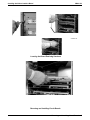
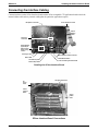
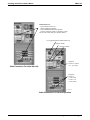
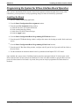
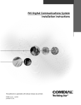
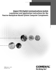
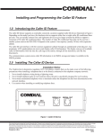
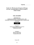
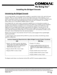
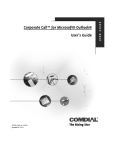
Installing the SCbus Interface Board
in the Impact FXS Digital Communications System
Introducing the SCbus Interface Board
The SCbus interface board allows Computer Telephony (CT) applications to connect one or more SCbus
compatible circuit boards in the Impact FXS computer (for example; network, voice, facsimile, speech
recognition, video, and so forth) to the Impact FXS’ digital station or trunk ports through time division
multiplexing (TDM) on the SCbus.
SCbus is a TDM bus for communications within a node of the Signal Computing System Architecture (SCSA).
(The SCSA standard specifies the signal processing system for PC-based voice and call processing, and telecom
switching.) The SCbus features an architecture that includes a serial message path for signaling and control and a
16-wire parallel Time Division Multiplexing (TDM) data path.
The conversion of a CTI application from traditional loop start ports to digital SCbus ports provides a more
effective and efficient operation than that provided by analog ports, which historically have been used in the CTI
industry.
CTI applications use the Enterprise or wideopen.office® toolkit in order to perform switching operations and call
processing on the Impact FXS SCbus interface board that is plugged into the Impact FXS proprietary telecom
backplane. These toolkits consist of PC software libraries that provide the instructions to the FX system for
performing these functions.
When installing more than one SCbus interface board, install the first one in the 6th (top) universal board slot of
the Impact FXS telephony portion and the next one in the 5th universal board slot, and so forth. Connect the
SCbus interface board’s ribbon cable to the CTI application board that is plugged onto the Impact FXS
computer’s motherboard. The internal cable connection between the SCbus board and the CTI application board
routes the voice-path between the two locations. Attach the PC power cable from the power supply to the SCbus
interface board to the first SCbus interface board you installed. Any subsequent SCbus interface boards you install
do not require the power connection. In addition to these internal cables, the installation requires external cabling
between the Impact FXS system’s computer and telephony portion. The particular external cabling required is
dependent upon the CTI application being operated. For example, when using a voice mail application, a cable is
required to connect the computer’s COM 2 port to the telephony’s COM 2 port. The cabling requirements are
illustrated in the figure on page 7 of this instruction.
An SCbus installation includes the following items:
• SCbus Interface Board (product code FXSCBUS),
• SCbus Application Board or Boards (as needed),
• Enterprise ToolKit Software including all required disks (product code ENTRP-SW).
wideopen.office® is a registered trademark of Comdial Corporation, Charlottesville, VA
This manual has been developed by Comdial Corporation (the “Company”) and is intended for the use of its customers and service personnel. The information in this manual is subject to change without notice. While every effort
has been made to eliminate errors, the Company disclaims liability for any difficulties arising from the interpretation of the information contained herein.
The information contained herein does not purport to cover all details or variations in equipment nor to provide for every possible contingency to be met in connection with installation, operation, or maintenance. Should further
information be desired, or should particular problems arise which are not covered sufficiently for the purchaser’s purposes, contact Comdial, Inside Sales Department, Charlottesville, Virginia 22906.
Printed in U.S.A.
IMI89–313.01
2/99
IMI89–313
Installing the SCbus Interface Board
Reviewing Technical Specifications
• Runs in SCbus mode—does not support the Pulse Code Modulation Expansion Bus (PEB) mode
• Runs at 4MHz bus speed with 8MHz clock speed
• Provides non-blocking switching between 32 full-duplex Impact FXS telecom ports on the interface board
and the 1024 SCbus time slots. This means that the switch block can connect any of the 32 receive or
transmit FX backplane time slots to any of the 1024 time slots on the SCbus.
• Runs as SCbus clock master or clock slave. The clock slave configuration requires a Sync card on the Impact
FXS (or an AUX board), and two elastic buffer integrated circuit components (IC chips) installed on the
SCbus interface board. The elastic buffers are not required for the clock master configuration.
• Interface cable has 21-inch maximum length per SCbus standard. Cable allows SCbus interface board to
support maximum of 32 installed SCbus boards. Standard default cable shipped with board provides for four
SCbus boards in the Impact FXS computer portion and three SCbus interface boards in the Impact FXS
telephony portion.
Considering Related Publications
• Installing The Impact FXS Common Equipment Cabinet, Comdial pub number IMI66–134
• The SCSA Hardware Model Specification, Version 3.0, 11/94, Dialogic* pub number 05-0104-007
* Dialogic Corporation, Parsippy NJ 07054
Complying with Underwriters Laboratories Regulations
Per The Underwriters Laboratories regulation 1950, be aware of the following precautions when installing
telephone equipment that is to be directly connected to the telephone company network:
• never install telephone wiring during a lightning storm,
• never install telephone jacks in wet locations unless the jack is specifically designed for wet locations,
• never touch uninsulated telephone wires or terminals unless the telephone line has been disconnected at the
network interface,
• use caution when installing or modifying telephone lines,
• avoid using a telephone (other than a cordless type) during an electrical storm—there may be a remote risk of
electrical shock from lightning,
• do not use the telephone to report a gas leak in the vicinity of the leak.
2 – Introducing the SCbus Interface Board
Installing the SCbus Interface Board
IMI89–313
Removing and Installing Circuit Boards
CAUTION
Circuit boards for the Impact FXS system are susceptible to damage caused by electrostatic discharge,
and you must keep this fact in mind as you handle the circuit boards. Refer to the Comdial publication
IMI01-005, Handling Of Electrostatically Sensitive Components, for general information Specific
handling precautions are also included in this installation instruction.
The Impact FXS system may include some installed circuit boards when it arrives at your site. The system
consists of two parts—the computer portion and the telephony portion. In the telephony portion of the Impact
FXS system, the equipment cabinet provides universal slots that will accept either line or station boards.
When removing or installing circuit boards in the Impact FXS cabinet, you must install a static discharge wrist
strap on your bare wrist, and adjust it for a snug fit. Be sure that the strap is touching bare skin and is not isolated
by clothing. Connect the wrist strap cord between the wrist strap and a AC or earth ground.
Unless a circuit board has a pre-charge port on its front panel, disconnect the AC power cord from the AC service
outlet and disconnect the cable between the cabinet and any external battery back-up assembly before you remove
or install the circuit board. However, if the board does include a pre-charge port, you can connect a standard
telephone handset cord between the pre-charge port on the circuit board and the pre-charge port on the power
supply assembly and remove or install the circuit board while the system is operating.
Whenever you remove a circuit board from the cabinet, immediately place the board in a static protection bag
while you still have your wrist strap in place and properly grounded.
Creating a Static-Safe Work Area
When removing circuit boards from an installation location for servicing, always transport them to a static-safe
work area in static protection bags. If you do not already have a static-safe work area, you can create one by
arranging a work area as detailed in the illustration.
Static
Wrist
Strap
Common Point Ground
ESD Protective
Mat
Typical Earth
Ground
ESD Protective
Worksurface
Static 2
ESD Protective
Mat
Creating a Static-Safe Work Area
Removing and Installing Circuit Boards – 3
IMI89–313
Installing the SCbus Interface Board
Removing and Installing SCbus Interface Boards
1. Normally you should disconnect the AC power cord from the AC outlet and disconnect the optional battery
back-up assembly from the power supply; however, when necessary, you can remove or install some
printed wiring boards in an operating system. If you must do this, connect one end of a standard telephone
handset coil cord to the precharge port on the power supply. During step 5, you will connect the other end
of this coil cord to the precharge jack on the printed wiring board.
CAUTION
If the board you need to install or remove does not include a precharge jack, you must not install or
remove it in a powered system.
2. Install your static discharge wrist strap on your bare wrist; adjust it for a snug fit. Be sure that the strap is
touching bare skin and is not isolated by clothing. Connect the wrist strap cord between the wrist strap and
an AC or earth ground
NOTE: With the common equipment in the installed position, the ground lug on the side of the cabinet is an
appropriate grounding point since it should have a heavy ground wire connected between it and a good
earth ground.
3. Each new board is supplied in a static protection bag for safe keeping. When you are ready to install the
board, remove it from its static protection bag. Conversely, when you remove a board from the cabinet,
immediately place it in a static protection bag.
4. Locate the proper board slot. (Most line, station, and special purpose interface boards use the universal
slots.) When installing the first SCbus board, use the 6th (top) universal slot to insure a proper connection to
the PC power cable. Any subsequent SCbus boards installed do not require the PC power connection.
5. If you are removing or installing the board in an operating system, connect the free end of the precharge
cord that you installed in step 1 to the precharge jack on the line board.
6. If you are removing boards from the cabinet, remove the retaining hardware, pull the boards toward you
until their board edge connectors separate from the cabinet’s backplane connection, and slide the boards
free of the cabinet.
7. To install boards, orient them with the
left and right guides in cabinet board
cage. and press the boards firmly until
their board edge connectors properly
mate with the connection on the
cabinet’s backplane.
8. Make a final inspection to ensure that
all boards are oriented correctly and
mated properly.
9. Install and tighten the supplied screws
to secure the installed boards to the
board cage.
10. If you are installing line boards, note
that each board includes a ferrite collar.
Snap the ferrite collar around the cable
to provide protection against radio
frequency interference.
4 – Removing and Installing Circuit Boards
Power Supply Assembly
Pre-charge Port Location
Typical Circuit Board
Pre-charge Port Location
Universal Board Slots 1 through 6
(Used for Line or Station Boards)
Dedicated CPU Board Slot
Dedicated Auxiliary Board Slot
fulbox2.cdr
Locating Circuit Boards
Installing the SCbus Interface Board
IMI89–313
screws2.cdr
Locating the Board-Retaining Hardware
remove.cdr
Removing and Installing Circuit Boards
Removing and Installing Circuit Boards – 5
IMI89–313
Installing the SCbus Interface Board
Connecting the Interface Cabling
Connections between the SCbus Interface board and the SCbus compatible CTI application board include the
internal ribbon cable and any external cabling that the particular application requires.
Backplane Connector
To PC Board Connector
SCbus
Ribbon
Cable
PC Power
Connector
Elastic Buffers
(optional) for
SCbus Clock
Slave Configuration
scbus_1.cdr
Precharge Jack
SCbus Ribbon Cable Connector
Status LED
Transmit Slip LED
Receive Slip LED
Board Reset Button
Loss Of Clock Synch Alarm LED
Detailing the SCbus Interface Board
CTI Application Board
PC
Power
Cable
SCbus
Interface
Board
SCbus
Ribbon
Cable
scbus_2.cdr
SCbus Interface Board Connections
6 – Connecting the Interface Cabling
Installing the SCbus Interface Board
IMI89–313
Maintenance Port
- System Software Turn On
- Initial VMMI Programming
- pcANYWHERE for Remote Operation
Connect Computer COM1 To Telephony COM1
(See text for remote data pipe operation details.)
CTI Application Key/Parallel Printer Port
Computer COM 1
Computer COM 2
Cable Connection For Initial Start-Up
Computer
COM 5- 8 (4 Port)
or 5 - 12 (8 Port)
Telephony
COM 1- 6
(1 Com card)
or Com 1 -10
(2 Com cards)
pc_conn6.cdr
Cable Connections For Normal Operation
Connecting the Interface Cabling – 7
IMI89–313
Installing the SCbus Interface Board
Programming the System for SCbus Interface Board Operation
Once you have installed the SCbus interface board in the equipment cabinet and made the necessary cable
connections, you must perform several programming changes to make the board fully operational.
Installing the Board
1. Start the VMMI programming application.
2. Go to the Board Configuration/Slot Assignment location.
3. From the open Slot Assignment dialog window,
(a) click the slot where you installed the board,
(b) click open the board type dialog,
(c) click on the FX-SCB SC Bus board type,
(d) click the Apply button.
4. Go to the Board Configuration/Board Programming/PCTB Boards location.
5. From the open PCTB Boards dialog window, configure the master clock setting as needed. Refer to the next
section.
6. Go to the Board Configuration/Board Programming/SC Bus Ports location.
7. From the open SC Bus Ports dialog window, configure each SC port for Port Type and OAI Link. Refer to
the next section.
8. Test the installation to determine that the board is synchronized with Impact FXS’ CPU board.
Once installed, the system creates 32 additional station ports that correspond with the 32 telecom ports on the
SCbus interface board. (Future software and hardware revisions will enable installers to program these telecom
ports to be either station or line boards. At present, these ports can only be programmed for station boards or
disabled.)
8 – Programming the System for SCbus Interface Board Operation
Installing the SCbus Interface Board
IMI89–313
Configuring the Clock
For proper operation, you must only configure one SCbus board as the master clock on a given SCbus ribbon
cable. This means that while you must configure one SCbus interface board as a clock master, you also must
configure any other SCbus boards that you connect along the same ribbon cable as clock slaves. This requirement
includes other SCbus interface boards that you install in the Impact FXS telephony portion as well as any SCbus
compatible application boards that you install in the Impact FXS computer portion. You will need to consult the
literature that accompanies the SCbus application boards to learn how to configure them as clock slaves or
masters.
If you configure all the SCbus compatible application boards that you have installed in the Impact FXS telephony
portion as clock slaves, you must configure at least one SCbus compatible application board that you install in the
Impact FXS computer portion as a clock master. That clock configuration arrangement also requires you to make
the following hardware considerations:
• you must install a T1 Sync card on the Impact FXS AUX board (reset the Impact FXS system after installing
the Sync card to cause the system to recognize it),
• you must configure one of the SCbus interface boards as a clock master,
• install the two elastic buffer ICs on each SCbus interface board.
NOTE: Currently, if you have a requirement for this clock configuration, you must obtain from your Comdial
supplier a different SCbus interface board that includes the optional IC chip set.
Further, if you do not properly configure the SCbus clock, the system turns the red SYNC ALARM
indicator on steady.
Configuring the SCbus Interface Board as the Master Clock
As a default, the master clock is disabled on a newly installed SCbus interface board. If you plan for that board to
serve as the master clock you must configure it as such.
1. Start the VMMI programming application.
2. Go to the Board Configuration/Board Programming/PCTB Boards location.
3. From the open PCTB Boards dialog window, click the SCbus board that you need to configure.
4. From the dialog window for the selected board, select the master clock mode to be enabled or disabled as
needed.
5. Click the Apply button.
Configuring the SCbus Speed
At present, the SC bus speed is set for 4.096 Mbps and cannot be changed. The maximum SCbus time slot value
corresponding to this speed is 1023.
Programming the System for SCbus Interface Board Operation – 9
IMI89–313
Installing the SCbus Interface Board
Configuring the SCbus Ports
You configure the 32 SC ports as station ports or disabled ports.
1. Start the VMMI programming application.
2. Go to the Board Configuration/Board Programming/SC Bus Ports location.
3. From the open SC Bus Port dialog window, click the SCbus board that you need to configure.
4. From the dialog window for the selected board, select the Port Type. At present, the only choices are
Station or None.
5. Select the OAI Link by clicking on the box to expand the menu. At present, the choices are None and 1
through 10. The OAI Link allows you to specify an optional default link for personal computer applications
that use preconfigured ports.
Configuring the SCbus Time Slots
The Impact FXS' SCbus interface board is compatible with the Dialogic standards for SCbus technology. The
Comdial Enterprise Toolkit provides two utilities that allow the Impact FXS system to comply with the Dialogic
standards.
• FXTSREQ.EXE—this utility determines the number of SCbus transmit time slots needed by an Impact FXS
system. Each installed SCbus interface board requires 32 transmit SCbus time slots.
• FXTSMAP.EXE—this utility assigns 32 SCbus transmit time slots to each installed SCbus interface board.
These two utilities are part of the Enterprise ToolKit developer software. You must copy them from their source
location to the BIN directory of the Dialogic system software (for example: C:\DLGCDEV\DIALOGIC\BIN if
you installed the Dialogic system software in C:\DLGCDEV).
CAUTION
You must run the FXTSREQ.EXE utility before you start the Dialogic service. Refer to the Dialogic
documentation for start and stop details. The Dialogic system software calls the FXTSMAP.EXE utility
software when it needs to do so. Never run FXTSMAP.EXE manually. It’s the Dialogic system
software’s responsibility to call FXTSMAP.EXE with the proper arguments.
Currently, the utility is not a Windows* NT* service; therefore, you must start the Dialogic service
manually rather that automatically. This requirement is so that the FXTSREQ.EXE utility can run
before you start the Dialogic service software. After the utility becomes Windows NT compliant, the
only requirement will be that the utility runs to completion before the Dialogic system software starts.
*Windows and Windows NT are registered trademarks of Microsoft Corp., Redmond WA.
R
Charlottesville, Virginia 22901-2829
World Wide Web: http://www.comdial.com/