1
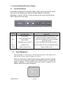
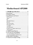
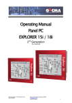
USER’S MANUAL
for the
Model CFP24W2
24 INCH AMLCD FLAT PANEL COLOR
MONITOR
Document # 150-CF24-101
Nov 2009
1 Riga Lane, Birdsboro, PA 19508 USA
Telephone: 610-404-7400 * Fax: 610-404-8190 * www.aydindisplays.com
Table of Contents
1.
2.
3.
Introduction.......................................................................................................3
Specifications ...................................................................................................3
Front Panel Buttons/On-Screen Display...........................................................4
3.1. Front Panel Buttons...................................................................................4
3.2. Power Management ..................................................................................4
4. On-Screen Control Function Items ...................................................................6
4.1. OSD (ON SCREEN DISPLAY) – PRE ADJUSTMENT NOTICE ..............6
4.1.1. OSD Timeout Period ..........................................................................6
4.1.2. OSD Activation...................................................................................6
4.1.3. OSD Menu: ........................................................................................6
4.2. OSD (ON SCREEN DISPLAY) – STORED VALUES ...............................7
4.3. OSD MENU NAVIGATION – MAIN MENU (VGA or DVI Main Source)....7
4.4. OSD MENU NAVIGATION – IMAGE MENU (MAIN VGA MODE)............8
4.5. OSD MENU NAVIGATION – PIP MENU ................................................10
4.6. OSD MENU NAVIGATION – COLOR MENU .........................................11
4.7. OSD MENU NAVIGATION – CONTROLS MENU ..................................12
4.8. OSD MENU NAVIGATION – OSD/RESET MENU – FACTORY RESET13
4.9. OSD MENU NAVIGATION – OSD/RESET MENU – STANDARD
FUNCTIONS ......................................................................................................15
4.10.
OSD MENU – SAMPLE IMAGES........................................................16
5.0 Touch Screen Drivers………………………………………………………………18
6.0 Maintenance……………………………………………………………………..…19
150-CF24-101
2 of 19
1.
Introduction
The Model CFP24W2 AMLCD Monitor is a 24” diagonal display with a native
resolution of 1600 x 1200 (WUXGA). The display is designed to operate from
115/220 VAC, 60Hz, single phase. Inputs are provided for DVI-D, VGA and Video.
Generally all VESA compatible video formats are supported. If a mode isn’t
supported, the factory can add special modes. Picture-in Picture (PIP) mode can
be provided as an option.
2.
Specifications
Specifications
Environmental
Display Type: 24.0” WUXGA TFT
Active Display Area: 20.41”(w) x 12.76”(h)
(518.4 x 324.0mm)
Pixel Pitch: .270 mm
Brightness: 500 nits
Viewing Angle: Left/Right 89º/89º
Up/Down 89º/89º
Contrast Ratio: 1000:1
Response Time: Tr=16; Tf=8
Display Colors: 16.7M
Horizontal: 31.5 to 80kHz
Synchronization
Range:
Vertical: 60 to 76Hz
Input Signal:
Video: Analog 0.7V p-p/75 !
Sync: Separate sync. TTL level
Horizontal Sync: Positive/Negative
Vertical Sync: Positive/Negative
Composite Sync: Positive/Negative
Sync on Green (Video 0.7Vp-p
and Sync 0.3Vp-p)
Input Interface: VGA (HD-15), DVI-D, NTSC (RCA),
S-Video (5 pin DIN)
Video Input 75 Ohms
Impedance:
Resolutions
640 x 480
Supported:
800 x 600
1024 x 768
1280 x 1024
1600 x 1200
150-CF24-101
Temperature:
Humidity:
(Non-Condensing)
Altitude:
Shock:
Vibration:
Power
Requirements:
Dimensions
(w/o stand):
Touch Option:
Touch Interface:
@ 60, 72, 75, 85
@ 60, 70, 72, 75, 85
@ 60, 70, 72, 75
@ 60, 70, 75, 85
@ 60 (native)
3 of 19
Operating: 0°C to 50°C
Storage: -20°C to +70°C
Operating: 10 to 90%
Storage: 10 to 90%
Operating: 0 to 12,000 ft.
Storage: 0 to 40,000 ft.
30g, 11ms, ! Sine
1g RMS 20-500Hz
Voltage: Internal 88-264 Volts
VAC auto ranging @
47-63 Hz
Power: 100 W Nominal
Current: 1.2 @ 120 V (Typical)
Height: 16.61” (421.9 mm)
Width: 24.27” (616.5 mm)
Depth: 3.1270” (79.43 mm)
Weight: 20 lbs (9.07 kg)
Resistive
USB, Serial
3. Front Panel Buttons/On-Screen Display
3.1.
Front Panel Buttons
Press MENU to display the On-Screen-Display (OSD). Use the ▲ and ▼ to move
the cursor to the desired menu selection and press MENU to access the
adjustment or function. With the √ button you can exit the current function and go
back to the previous menu point.
BUTTON
▼
OPERATION PERFORMED IF OSD
NOT DISPLAYED
DECREASES BACKLIGHT
BRIGHTNESS
OPERATION PERFORMED WHEN OSD
DISPLAYED
SELECTS NEXT MENU OPTION OR NEXT SUBMENU OPTION OR DECREASE SELECTED VALUE
SELECTS PREVIOUS MENU OPTION OR
PREVIOUS SUB-MENU OPTION OR INCREASE
SELECTED VALUE
▲
INCREASES BACKLIGHT
BRIGHTNESS
√
PERFORMS AUTO ADJUST
EXITS SUB-MENU OPTION OR EXITS OSD
MENU
ENABLES OSD
SELECTS MENU OPTION OR SUB-MENU OPTION
POWER
TURNS POWER ON/OFF
TURNS POWER ON/OFF
3.2.
Power Management
When Horizontal or Vertical Sync is not detected, the amber SAVE indicator will
light and the No Sync symbol will appear (see below).
When the Horizontal or Vertical Synchronization frequencies being supplied
to the unit are not within the range of the AMLCD monitor, or when No
Signal is applied, or if the wrong video input source is selected in the
display, the No Sync symbol will appear.
No
Sync!
150-CF24-101
4 of 19
To extinguish the No Sync symbol and display an image, do one of the
following:
-
Supply a format with Horizontal or Vertical Synchronization frequencies
that are compatible with the display.
-
Connect a video source to the selected video input on the display
-
Enable the correct video input source by pushing the ‘√’ button and
select the desired video input source using the OSD.
150-CF24-101
5 of 19
4.
On-Screen Control Function Items
4.1.
OSD (ON SCREEN DISPLAY) – PRE ADJUSTMENT NOTICE
4.1.1.
OSD Timeout Period
The OSD (On Screen Display) has a user-selectable Timeout Period.
If the OSD is activated and no front panel keys are depressed for a period of 5 to
60 seconds, the OSD will automatically deactivate. Any adjustments made prior to
timeout will be stored.
If the Timeout Period is set to zero, the OSD will remain continuously enabled,
until deactivated by one of the following conditions:
•
Pressing the “√” key as often as required to reach and exit the Top Level
menu
•
Unit power is turned off
The Timeout Period function is accessed via the OSD/RESET menu.
4.1.2.
OSD Activation
If the OSD (On Screen Display) is not visible, press the “MENU” key, once, to
activate the OSD.
4.1.3.
OSD Menu:
Observe the following Top-Level Menu Selection Tabs on the OSD Menu:
•
•
•
•
•
•
MAIN
IMAGE (Not shown when DVI input selected)
PIP
COLOR
CONTROLS
OSD/RESET
MAIN is the default foreground menu; the active menu will always appear in the
foreground.
The Selection Tab of the active menu will be highlighted in blue.
Press the “√” key once to deactivate the OSD.
See the OSD – SAMPLE IMAGES section of this document for sample images of
OSD menus.
150-CF24-101
6 of 19
4.2.
OSD (ON SCREEN DISPLAY) – STORED VALUES
Values chosen during OSD interaction are stored in memory under the following
conditions:
•
•
The “√” is pressed
Timeout period expires
Values chosen during OSD interaction are not stored in memory under the
following conditions:
•
Unit power is turned off prior to pressing the “√” key
•
Unit power is turned off prior to the expiration of the timeout period
Values stored in memory are retained indefinitely. Unit power is not required to
retain stored values.
4.3.
OSD MENU NAVIGATION – MAIN MENU (VGA or DVI Main
Source)
If the OSD is not visible, press the “MENU” key once to activate the OSD.
Observe the following choices in the MAIN Menu Selection List:
Source - (Multiple Sub-Function Selection Buttons)
NOTE:
MAIN Source and PIP Source, VGA and DVI selections, are mutually
exclusive. MAIN Source and PIP Source cannot be set to same input
source with the OSD.
• Scaling - (Multiple Sub-Function Selection Buttons)
• Brightness - (Level Adjust Function)
• Contrast - (Level Adjust Function)
• Hue - (Level Adjust Function)
• Saturation - (Level Adjust Function)
• Black Level - (Level Adjust Function) (Not shown when DVI input
selected)
•
Press the “MENU” key again to activate the MAIN menu. The OSD will auto-index
to the first selection (Source) on the menu list. The selection will be highlighted
with a raised background and a blue indicator dot as per the example below.
Source
Press the [▼] or [▲] keys to navigate through the Selection List
When the desired selection is highlighted, press the “MENU” key to access the
highlighted selection
After the desired selection is activated, press the [▼] or [▲] keys to perform the
following:
150-CF24-101
7 of 19
1) Choose the desired Sub-Function.
The currently selected Sub-Function will be distinguished by the white font
color displayed on the Selection Button.
Example:
Source
VGA
DVI
After the desired Sub-Function is highlighted, press the “MENU” key to
activate the highlighted Sub-Function
Press the “√” key one time to resume navigation in the Menu Selection
List
2) Adjust the desired Level.
Example:
Adjustment Indicator
Bar
Brightness
After the desired selection is activated, press the [▼] or [▲] keys to set
the desired level.
Press the “√” key one time to activate the desired level and resume
navigation in the MAIN Menu Selection List
Press the “√” key one additional time to resume navigation in the Top- Level OSD
menu.
Pressing “√” while in the Top-Level of the OSD menu will deactivate the OSD.
4.4.
OSD MENU NAVIGATION – IMAGE MENU (MAIN VGA MODE)
If the OSD is not visible, press the “MENU” key, once, to activate the OSD.
Navigate to the MAIN menu and set the Source to “VGA”, before proceeding.
Press the [▼] or [▲] keys to navigate to the IMAGE menu
Observe the following choices in the IMAGE Menu Selection List:
•
•
•
•
•
•
150-CF24-101
Auto Adjust - (Single Sub-Function Selection Button)
Auto Gain - (Single Sub-Function Selection Button)
Phase - (Level Adjust Function)
Clock - (Level Adjust Function)
Horizontal Position - (Level Adjust Function)
Vertical Position - (Level Adjust Function)
8 of 19
When the IMAGE menu is highlighted, press the “MENU” key to access the
IMAGE menu. The OSD will auto-index to the first selection (Auto Adjust) on the
menu list. The selection will be highlighted with a raised background and a blue
indicator dot as per the example below.
Auto Adjust
Press the [▼] or [▲] keys to navigate through the Selection List
The Auto Adjust and Auto Gain selections have only one Sub-Function Selection
Button. The Sub-Function Selection Buttons for either of these modes are autoselected and highlighted in blue, when chosen from the selection list. See
examples below:
Auto Adjust
Select
Auto Gain
Select
When the desired selection is highlighted, press the “MENU” key to activate the
highlighted selection
The remaining items in the IMAGE Menu Selection List are associated with Level
Adjust Functions
Example:
Adjustment Indicator
Bar
Phase
Press the [▼] or [▲] keys to navigate through the Selection List.
Press the “MENU” key to activate the desired level function.
After the desired selection is activated, press the [▼] or [▲] keys to set
the desired level.
Press the “√” key one time to accept the desired level and resume
navigation in the IMAGE Menu Selection List.
Press the “√” key one additional time to resume navigation in the Top- Level OSD
menu.
Pressing “√” while in the Top-Level of the OSD menu will deactivate the OSD.
150-CF24-101
9 of 19
4.5.
OSD MENU NAVIGATION – PIP MENU
If the OSD is not visible, press the “MENU” key once to activate the OSD. Press
the [▼] or [▲] keys to navigate to the PIP menu
Observe the following choices in the PIP Menu Selection List:
Source - (Multiple Sub-Function Selection Buttons)
•
NOTE:
MAIN Source and PIP Source, VGA and DVI are mutually exclusive. MAIN
Source and PIP Source cannot be set to the same input source
• Enable - (Multiple Sub-Function Selection Buttons)
• Size - (Multiple Sub-Function Selection Buttons)
• Horizontal Position - (Level Adjust Function)
• Vertical Position - (Level Adjust Function)
• PIP Brightness - (Level Adjust Function)
• PIP Contrast - (Level Adjust Function)
Press the “MENU” key again to activate the PIP menu. The OSD will auto-index to
the first selection (Source) on the menu list. The selection will be highlighted with
a raised background and a blue indicator dot as per the example below:
Source
Press the [▼] or [▲] keys to navigate through the Selection List.
When the desired selection is highlighted, press the “MENU” key to access the
highlighted selection.
After the desired selection is activated, press the [▼] or [▲] keys to perform the
following:
1) Choose the desired Sub-Function.
The currently selected Sub-Function will be distinguished by the white font
color displayed on the Selection Button.
Example:
Source
VGA
DVI
After the desired Sub-Function is highlighted, press the “MENU” key to
activate the highlighted Sub-Function.
Press the “√” key one time to resume navigation in the Menu Selection
List.
150-CF24-101
10 of 19
2) Adjust the desired Level.
Example:
Adjustment Indicator
Bar
Brightness
After the desired selection is activated, press the [▼] or [▲] keys to set
the desired level.
Press the “√” key one time to accept the desired level and resume
navigation in the PIP Menu Selection List.
Press the “√” key one additional time to resume navigation in the Top Level OSD
menu.
Pressing “√” while in the Top-Level of the OSD menu will deactivate the OSD.
4.6.
OSD MENU NAVIGATION – COLOR MENU
If the OSD is not visible, press the “MENU” key once to activate the OSD. Press
the [▼] or [▲] keys to navigate to the COLOR menu.
Observe the following choices in the COLOR Menu Selection List:
•
•
•
•
•
sRGB - (Multiple Sub-Function Selection Buttons)
Color Temperature - (Multiple Sub-Function Selection Buttons)
Red - (Level Adjust Function)
Green - (Level Adjust Function)
Blue - (Level Adjust Function)
Press the “MENU” key again to activate the COLOR menu. The OSD will autoindex to the first selection (sRBG) on the menu list. The selection will be
highlighted with a raised background and a blue indicator dot as per the example
below:
sRGB
Press the [▼] or [▲] keys to navigate through the Selection List.
When the desired selection is highlighted, press the “MENU” key to access the
highlighted selection.
After the desired selection is activated, press the [▼] or [▲] keys to perform the
following:
150-CF24-101
11 of 19
1) Choose the desired Sub-Function.
The currently selected Sub-Function will be distinguished by the white font
color displayed on the Selection Button.
Example:
Off
sRGB
On
After the desired Sub-Function is highlighted, press the “MENU” key to
activate the highlighted Sub-Function.
Press the “√” key one time to resume navigation in the Menu Selection
List.
2) Adjust the desired Level.
Example:
Adjustment Indicator
Bar
Red
After the desired selection is activated, press the [▼] or [▲] keys to set
the desired level.
Press the “√” key one time to accept the desired level and resume
navigation in the COLOR Menu Selection List.
Press the “√” key one additional time to resume navigation in the Top- Level OSD
menu.
Pressing “√” while in the Top-Level of the OSD menu will deactivate the OSD.
4.7.
OSD MENU NAVIGATION – CONTROLS MENU
If the OSD is not visible, press the “MENU” key once to activate the OSD. Press
the [▼] or [▲] keys to navigate to the CONTROLS menu
Observe the following choices in the CONTROLS Menu Selection List:
• Backlight - (Level Adjust Function)
When the CONTROLS menu tab is highlighted, press the “MENU” key to access
the CONTROLS menu. The OSD will auto-index to the first selection (Back Light)
on the menu list. The selection will be highlighted with a raised background and a
blue indicator dot as per the example below:
Back Light
Press the [▼] or [▲] keys to navigate through the Selection List.
When the desired selection is highlighted, press the “MENU” key to access the
highlighted selection.
After the desired selection is activated, press the [▼] or [▲] keys to perform the
following:
150-CF24-101
12 of 19
1). Adjust the desired Level.
Example:
Adjustment Indicator
Bar
Back Light
After the desired selection is activated, press the [▼] or [▲] keys to set
the desired level.
Press the “√” key one time to accept the desired level and resume
navigation in the CONTROLS Menu Selection List.
Press the “√” key one additional time to resume navigation in the Top- Level OSD
menu.
Pressing “√” while in the Top-Level of the OSD menu will deactivate the OSD.
4.8.
OSD MENU NAVIGATION – OSD/RESET MENU – FACTORY
RESET
If the OSD is not visible, press the “MENU” key once to activate the OSD. Press
the [▼] or [▲] keys to navigate to the OSD/RESET menu
Observe the following choices in the OSD/RESET Menu Selection List:
•
•
•
•
•
Factory Reset - (Single Sub-Function Selection Button)
Horizontal - (Level Adjust Function)
Vertical - (Level Adjust Function)
Blend - (Level Adjust Function)
Time Out - (Time Adjust Function)
Press the “MENU” key again to activate the OSD/RESET menu. The OSD will
auto-index to the first selection (Factory Reset) on the menu list. The selection will
be highlighted with a raised background and a blue indicator dot. See example
below:
The Factory Reset selection has only one Sub-Function Selection Button. The
Sub-Function Selection Button for this mode is auto-selected and highlighted in
blue with a white font, when Factory Reset is chosen from the selection list. See
example below:
Factory Reset
Select
Pressing the “MENU” key when Factory Reset is highlighted will activate the
Factory Reset OSD. The Factory Reset OSD (On Screen Display) provides for
acceptance or rejection of the Factory Reset process. See Factory Reset OSD
example below:
150-CF24- 101
13 of 19
When the Factory Reset OSD is displayed, press the [▼] or [▲] keys to select
the following:
•
•
No (Default Selection) – Do Not Perform Factory Reset
Yes – Perform Factory Reset
If “No” is highlighted, press the “MENU” or “√” key to return to the OSD/RESET
menu.
If “Yes” is highlighted, press the “MENU” key to activate Factory Reset. All
previously saved settings will be lost when Factory Reset is activated.
150-CF24-101
14 of 19
4.9.
OSD MENU NAVIGATION – OSD/RESET MENU – STANDARD
FUNCTIONS
If the OSD is not visible, press the “MENU” key once to activate the OSD. Press
the [▼] or [▲] keys to navigate to the OSD/RESET menu
Observe the following choices in the OSD/RESET Menu Selection List:
Factory Reset - (Single Sub-Function Selection Button)
Horizontal - (Level Adjust Function)
Vertical - (Level Adjust Function)
Blend - (Level Adjust Function)
Time Out - (Time Adjust Function)
•
•
•
•
•
Press the “MENU” key again to activate the OSD/RESET menu. The OSD will
auto-index to the first selection (Factory Reset) on the menu list. The selection
will be highlighted with a raised background and a blue indicator dot. See example
below:
Factory Reset
Press the [▼] or [▲] keys to navigate through the Selection List.
When the desired (non Factory Reset) selection is highlighted, press the “MENU”
key to access the highlighted selection.
After the desired selection is activated, press the [▼] or [▲] keys to perform the
following:
1) Adjust the desired Level.
Example:
Adjustment Indicator
Bar
Horizontal
After the desired selection is activated, press the [▼] or [▲] keys to set
the desired level.
Press the “√” key one time to accept the desired level and resume
navigation in the COLOR Menu Selection List.
Press the “√” key one additional time to resume navigation in the Top- Level OSD
menu.
Pressing “√” while in the Top-Level of the OSD menu will deactivate the OSD.
150-CF24-101
15 of 19
4.10.
OSD MENU – SAMPLE IMAGES
MAIN - VGA
MAIN - DVI
IMAGE
PIP
COLOR
CONTROLS
150-CF24-101
16 of 19
OSD/RESET
150-CF24-101
17 of 19
5. Touch Screens
5.1 Drivers
Your newly purchased AMLCD display may have a Resistive Touch Option. If it does,
please install the following Touch Driver.
If you require further assistance, please contact Aydin Displays’ Customer Service at
610-404-7400 x 5322.
http://home.eeti.com.tw/web20/eg/drivers.htm
150-CF24-101
18 of 19
6. Maintenance
6.1 Preventive Maintenance
The only periodic maintenance recommended is exterior surface cleaning when
necessary.
The window and exterior surfaces may be cleaned with standard non-abrasive
glass cleaners applied with a soft cloth to avoid scratching the anti-reflective
coating on the glass panel.
6.2 Corrective Maintenance
The only field corrective maintenance recommended is fuse replacement . Any
other corrective maintenance should be deferred to the depot or factory.
6.3 Troubleshooting (No Picture)
a)
If no front panel indicators are lit the most likely cause is no power input:
1) Is power connected? (Make sure the power cord is fully seated.)
2) Is the POWER switch ON?
3) Is the fuse OK?
b)
If the Yellow NO SYNC indicator is lit, most likely the monitor is not
receiving a video input or that video input is not selected as the Main
Picture Channel Input. (See section 4.3)
6.4 Replaceable Parts
a spare fuse is provided with the LCD Display.
Fuse
Description:
150-CF24-101
Fuse, Glass, 3AG Slo-Blo, 2A/250V
19 of 19
Options
Bonded Faceplate
Touch Screen
Top Handles
Aydin Displays
CFP24W2 VESA Mount