1
Avaya
Installation and Configuration Guide
AVAYA P332G-ML
STACKABLE SWITCH
SOFTWARE VERSION 4.5
January 2004
avaya.com
© 2004 Avaya Inc. All rights reserved. All trademarks identified by the ® or TM are registered trademarks or
trademarks, respectively, of Avaya Inc. All other trademarks are the property of their respective owners
Document no. 10-300126
Contents
Preface
Section 1
Before you Install the P332G-ML.......................................................................I
Safety Information .............................................................................................. I
FCC Notice........................................................................................................... I
Conventions Used in the Documentation ....................................................... I
CLI Conventions ......................................................................................I
Notes, Cautions, and Warnings ........................................................... II
Warranty ............................................................................................................ II
Notice................................................................................................................. III
Avaya Support ................................................................................................. III
Overview
Chapter 1
Avaya P332G-ML Overview ............................................................................ 1
Introduction ........................................................................................................ 1
About the P332G-ML......................................................................................... 1
Avaya P332G-ML Highlights ........................................................................... 1
Layer 3 Features P330-ML ................................................................................ 2
Network Management and Monitoring ......................................................... 2
Device Manager (Embedded Web) ...................................................... 2
Command Line Interface (CLI) ............................................................. 2
Avaya Integrated Manager ................................................................... 3
Port Mirroring ......................................................................................... 3
SMON ....................................................................................................... 3
Fans, Power Supply, and BUPS-ML Monitoring ............................... 3
Chapter 2
Standards and Compatibility ........................................................................... 5
Avaya P330 Standards Supported................................................................... 5
IEEE .......................................................................................................... 5
IETF - Layer 2 .......................................................................................... 5
IETF - Layer 3 .......................................................................................... 5
IETF - Network Monitoring.............................................................................. 6
Chapter 3
Specifications ...................................................................................................... 7
P332G-ML Switch .............................................................................................. 7
Physical .................................................................................................... 7
Power Requirements ............................................................................. 7
Environmental ......................................................................................... 7
Safety ........................................................................................................ 8
Safety - AC Version ................................................................................ 8
Avaya P332G-ML User’s Guide
i
Table of Contents
Safety - DC Version .................................................................................8
EMC Emissions .......................................................................................8
Emissions ......................................................................................8
Immunity ......................................................................................8
Interfaces ..................................................................................................9
Basic MTBF ..............................................................................................9
Stacking Sub-module ......................................................................................... 9
Basic MTBF ..............................................................................................9
Approved SFF/SFP GBIC Transceivers........................................................ 10
Safety Information ................................................................................10
Laser Classification ....................................................................10
Usage Restriction .......................................................................10
Installation .............................................................................................11
Installing and Removing a SFF/SFP GBIC Transceiver ......11
Specifications .........................................................................................11
LX Transceiver ...........................................................................11
SX Transceiver ............................................................................11
Agency Approval ..................................................................................12
Gigabit Fiber Optic Cabling............................................................................ 12
Console Pin Assignments................................................................................ 13
Section 2
ii
Installation
Chapter 4
Installation......................................................................................................... 17
Required Tools.................................................................................................. 17
Site Preparation ................................................................................................ 17
Rack Mounting (Optional) .............................................................................. 19
Installing the X330STK-ML Stacking Sub-Module (Optional) .................. 20
Connecting Stacked Switches ......................................................................... 20
To connect stacked switches: ...............................................................20
Making Connections to Network Equipment .............................................. 23
Prerequisites ..........................................................................................23
Connecting Cables to Network Equipment ......................................23
Chapter 5
Powering Up the Avaya P330......................................................................... 25
Powering On – Avaya P330 Module AC ...................................................... 25
Powering On – Avaya P330 Switch DC ........................................................ 25
Post-Installation................................................................................................ 26
Chapter 6
Avaya P332G-ML Front and Rear Panels ..................................................... 27
Avaya P332G-ML Front Panel........................................................................ 27
Avaya P332G-ML Back Panel......................................................................... 30
BUPS-ML Input Connector ..................................................................31
Chapter 7
Establishing Switch Access ............................................................................. 33
Avaya P332G-ML User’s Guide
Table of Contents
Establishing a Serial Connection ................................................................... 33
Configuring the Terminal Serial Port Parameters ........................... 33
Connecting a Terminal to the Avaya P330 Serial port .................... 33
P330 Sessions .................................................................................................... 34
Assigning P330’s IP Stack Address ............................................................... 34
Establishing a Telnet Connection .................................................................. 35
Establishing an SSH Connection.................................................................... 35
Establishing a Modem (PPP) Connection with the P330 ........................... 36
Overview ................................................................................................ 36
Connecting a Modem to the Console Port ........................................ 36
Security Levels.................................................................................................. 37
Entering the Supervisor Level ............................................................ 37
Defining new local users .......................................................... 38
Exiting the Supervisor Level .................................................... 38
Entering the CLI .................................................................................... 38
Chapter 8
User Authentication......................................................................................... 39
Introduction ...................................................................................................... 39
SNMP Support ................................................................................................. 39
Introduction to SNMP .......................................................................... 39
SNMP Versions .......................................................................... 39
Managers and Agents ............................................................... 39
Manager/Agent Communication ........................................... 40
SNMPv1 ...................................................................................... 40
SNMPv2c .................................................................................... 41
SNMPv3 ...................................................................................... 41
SNMP Commands ................................................................................ 43
SSH Protocol Support...................................................................................... 46
Introduction to SSH .............................................................................. 46
SSH Commands .................................................................................... 47
SCP Protocol Support ...................................................................................... 48
RADIUS ............................................................................................................. 49
Introduction to RADIUS ...................................................................... 49
Radius Commands ............................................................................... 51
Telnet Client Support ...................................................................................... 52
Introduction to Telnet .......................................................................... 52
Telnet Commands ................................................................................ 52
Recovery Password.......................................................................................... 53
Introduction ........................................................................................... 53
Recovery Password Commands ......................................................... 53
Allowed Managers........................................................................................... 54
Allowed Managers Introduction ........................................................ 54
Allowed Managers CLI Commands .................................................. 54
Allowed Protocols............................................................................................ 55
Allowed Protocols Introduction ......................................................... 55
Avaya P332G-ML User’s Guide
iii
Table of Contents
Allowed Protocols CLI Commands ...................................................55
Section 3
Chapter 9
Configuration
P330 Default Settings ....................................................................................... 59
Configuring the Switch ................................................................................... 59
Avaya P330 Default Settings ...............................................................59
Chapter 10 Switch Configuration....................................................................................... 61
Introduction ...................................................................................................... 61
Basic Switch Configuration .................................................................61
System Parameter Configuration .......................................................62
Identifying the system ..............................................................62
Operating parameters ...............................................................62
Network Time Acquiring Protocols Parameter Configuration ......63
Uploading and Downloading Device Configurations and Images .......... 63
Layer 2 Configuration File ...................................................................64
Layer 3 Configuration File ...................................................................65
System Logging ................................................................................................ 67
System Logging Introduction ..............................................................67
System Logging Messages ........................................................67
Sinks .............................................................................................68
Applications ...............................................................................68
Syslog Servers ............................................................................69
Syslog Configuration CLI Commands ...................................70
Monitoring CPU Utilization ........................................................................... 71
Chapter 11 Avaya P330 Layer 2 Features.......................................................................... 73
Overview ........................................................................................................... 73
Ethernet.............................................................................................................. 74
Fast Ethernet ..........................................................................................74
Gigabit Ethernet ....................................................................................74
Configuring Ethernet Parameters .......................................................74
Auto-Negotiation .......................................................................74
Full-Duplex/Half-Duplex ........................................................74
Speed ...........................................................................................75
Flow Control ...............................................................................75
Priority ........................................................................................75
MAC Address ............................................................................76
CAM Table ..................................................................................76
Ethernet Configuration CLI Commands ...........................................77
Ethernet Implementation in the Avaya P332G-ML .........................78
VLAN Configuration ....................................................................................... 79
VLAN Overview ...................................................................................79
VLAN Tagging ......................................................................................80
iv
Avaya P332G-ML User’s Guide
Table of Contents
Multi VLAN Binding ........................................................................... 80
Automatic VLAN Learning ................................................................. 82
Ingress VLAN Security ........................................................................ 82
VLAN CLI Commands ........................................................................ 82
VLAN Implementation in the Avaya P332G-ML ............................ 83
Spanning Tree Protocol ................................................................................... 84
Overview ................................................................................................ 84
Spanning Tree Protocol ........................................................................ 84
Spanning Tree per Port ........................................................................ 84
Rapid Spanning Tree Protocol (RSTP) ............................................... 85
About the 802.1w Standard ..................................................... 85
Port Roles .................................................................................... 85
Spanning Tree Implementation in the P330 Family ........................ 86
Spanning Tree Protocol CLI Commands .......................................... 87
MAC Aging....................................................................................................... 89
Overview ................................................................................................ 89
Configuring the P330 for MAC Aging .............................................. 89
MAC Aging CLI Commands .............................................................. 90
LAG.................................................................................................................... 91
LAG Overview ...................................................................................... 91
LAG CLI Commands ........................................................................... 91
LAG Implementation in the Avaya P330 Family of Products ....... 92
Port Redundancy ............................................................................................. 93
Port Redundancy Operation ............................................................... 93
Intermodule Port Redundancy ........................................................... 94
Port Redundancy CLI Commands ..................................................... 94
IP Multicast Filtering ....................................................................................... 96
Overview ................................................................................................ 96
IP Multicast CLI Commands ............................................................... 97
IP Multicast Implementation in the Avaya P332G-ML ................... 97
RMON................................................................................................................ 98
RMON Overview .................................................................................. 98
RMON CLI Commands ....................................................................... 98
SMON .............................................................................................................. 100
SMON Overview ................................................................................ 100
Port Mirroring Configuration ...................................................................... 101
Port Mirroring Overview .................................................................. 101
Port Mirroring CLI commands ......................................................... 101
Port Mirroring Constraints ................................................................ 101
Weighted Queuing......................................................................................... 102
Implementation of Weighted Queuing in the P330-ML ............... 102
Weighted Queuing CLI Commands ................................................ 102
Port Classification .......................................................................................... 103
Overview .............................................................................................. 103
Avaya P332G-ML User’s Guide
v
Table of Contents
Port Classification CLI Commands ..................................................103
Stack Redundancy.......................................................................................... 104
Stack Health .................................................................................................... 104
Overview ..............................................................................................104
Implementation of Stack Health in the P330 Family .....................104
Stack Health CLI Commands ............................................................105
Chapter 12 Avaya P330 Layer 3 Features........................................................................ 107
Introduction .................................................................................................... 107
What is Routing? .................................................................................107
Routing Configuration .................................................................................. 109
Forwarding ..........................................................................................109
Multinetting (Multiple Subnets per VLAN) ...................................109
IP Configuration ............................................................................................. 110
IP Configuration CLI Commands ....................................................110
Assigning Initial Router Parameters ................................................111
Obtaining and Activating a License Key .........................................112
Obtaining a Routing License Key ..........................................113
Activating a Routing License Key .........................................115
License Key CLI Commands ..................................................115
RIP (Routing Interchange Protocol) Configuration................................... 117
RIP Overview ......................................................................................117
RIP2 .......................................................................................................118
RIP CLI Commands ............................................................................118
OSPF (Open Shortest Path First) Configuration ........................................ 120
OSPF Overview ...................................................................................120
OSPF CLI Commands ........................................................................121
Static Routing Configuration........................................................................ 122
Static Routing Overview ....................................................................122
Static Routing Configuration CLI Commands ...............................122
Route Preferences ................................................................................123
Route Redistribution...................................................................................... 124
Route Redistribution Commands .....................................................124
ARP (Address Resolution Protocol) Table Configuration ....................... 125
ARP Overview .....................................................................................125
The ARP Table .........................................................................126
ARP CLI Commands ..........................................................................126
BOOTP/DHCP (Dynamic Host Configuration Protocol) Relay
Configuration.................................................................................................. 127
BOOTP/DHCP Overview .................................................................127
BOOTP ......................................................................................127
DHCP ........................................................................................127
DHCP/BOOTP Relay .............................................................127
BOOTP/DHCP CLI Commands .......................................................128
NetBIOS Re-broadcast Configuration ......................................................... 129
vi
Avaya P332G-ML User’s Guide
Table of Contents
NetBIOS Overview ............................................................................. 129
NetBIOS Re-broadcast Configuration CLI Commands ................ 129
VRRP (Virtual Router Redundancy Protocol) Configuration ................. 130
VRRP Overview .................................................................................. 130
VRRP Configuration Example 1 ....................................................... 131
Case#1 ....................................................................................... 131
Case #2 ...................................................................................... 132
VRRP CLI Commands ....................................................................... 132
SRRP Configuration....................................................................................... 134
SRRP Overview ................................................................................... 134
SRRP Configuration Example ........................................................... 134
SRRP CLI Commands ........................................................................ 135
Policy Configuration ..................................................................................... 136
Policy Configuration Overview ........................................................ 136
Policy Configuration CLI Commands ............................................. 136
Policy Configuration Example .......................................................... 138
Policy Configuration Example .......................................................... 138
IP Fragmentation and Reassembly.............................................................. 140
IP Fragmentation and Reassembly Overview ................................ 140
IP Fragmentation/Reassembly CLI Commands ............................ 140
Section 4
Troubleshooting and Maintaining the
Chapter 13 Troubleshooting the Installation.................................................................. 143
Troubleshooting the Installation.................................................................. 143
Chapter 14 Maintenance.................................................................................................... 145
Introduction .................................................................................................... 145
Replacing the Stacking Sub-module ........................................................... 145
Chapter 15 Updating the Software .................................................................................. 147
Software Download ....................................................................................... 147
Obtain Software Online ..................................................................... 147
Downloading Software ...................................................................... 147
Download New Version without Overwriting Existing Version ........... 148
Avaya P332G-ML User’s Guide
vii
Table of Contents
viii
Avaya P332G-ML User’s Guide
Preface
Before you Install the P332G-ML
Safety Information
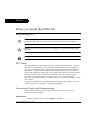
Caution: Avaya P330 switches and modules contain components sensitive to
electrostatic discharge. Do not touch the circuit boards unless instructed to do so.
Caution: Do not leave any slots open. Cover empty slots using the blanking plates
supplied.
Warning: The fans are on whenever the power is on in the chassis.
FCC Notice
This equipment has been tested and found to comply with the limits for a Class A
digital device, pursuant to part 15 of the FCC Rules. These limits are designed to
provide reasonable protection against harmful interference when the equipment is
operated in a commercial environment. This equipment generates, uses, and can
radiate radio frequency energy and, if not installed and used in accordance with the
instruction manual, may cause harmful interference to radio communications.
Operation of this equipment in a residential area is likely to cause harmful
interference in which case the user will be required to correct the interference at his
own expense.
Changes or modifications to this equipment not expressly approved by Avaya Inc.
could void the user’s authority to operate the equipment.
Conventions Used in the Documentation
Documentation for this product uses the following conventions to convey
instructions and information:
CLI Conventions
• Mandatory keywords are in the computer bold font.
Avaya P332G-ML User’s Guide
I
•
•
•
•
•
•
Information displayed on screen is displayed in computer font.
Variables that you supply are in pointed brackets <>.
Optional keywords are in square brackets [].
Alternative but mandatory keywords are grouped in braces {} and separated by
a vertical bar |.
Lists of parameters from which you should choose are enclosed in square
brackets [ ] and separated by a vertical bar |.
If you enter an alphanumeric string of two words or more, enclose the string in
inverted ”commas”.
Notes, Cautions, and Warnings
L Notes contain helpful information or hints or reference to material in other
documentation.
Caution: You should take care. You could do something that may damage
equipment or result in loss of data.
Warning: This means danger. Failure to follow the instructions or warnings may
result in bodily injury. You should ensure that you are qualified for this task and
have read and understood all the instructions
Warranty
Avaya Inc. provides a limited warranty on this product. Refer to your sales
agreement or other applicable documentation to establish the terms of the limited
warranty. In addition, Avaya’s standard warranty language as well as information
regarding support for this product, while under warranty, is available through the
following website: http://www.avaya.com/support.
II
Avaya P332G-ML User’s Guide
Notice
Every effort was made to ensure that the information in this document was
complete and accurate at the time of printing. However, information is subject to
change.
Avaya Support
Avaya provides a telephone number for you to use to report problems or to ask
questions about your contact center. The support telephone number is 1-800-2422121 in the United States. For additional support telephone numbers, see the Avaya
Web site: http://www.avaya.com
Avaya P332G-ML User’s Guide
III
IV
Avaya P332G-ML User’s Guide
Avaya
SECTION 1: OVERVIEW
Chapter 1
Avaya P332G-ML Overview
Introduction
The P332G-ML is a powerful Multilayer Policy Gigabit Ethernet stackable switch. It
enhances the P330 line to support high density multilayer Gigabit Ethernet
solutions.
The Avaya P330 family of stackable Ethernet workgroup switches includes a range
of modules with 10/100/1000 Mbps ports, a Layer 3 capability, and ATM and WAN
expansion modules.
An Avaya P330 stack can contain up to 10 switches and backup power supply units.
The stacked switches are connected using stacking Modules which plug into a slot
in the back of the Avaya P330. They are connected using the X330SC or X330LC
cable (if the stack is split between two racks). The Avaya X330RC cable connects the
top and bottom switches in the stack; this connection provides redundancy and
hot-swappability. A P330 stack is managed as a single IP entity.
About the P332G-ML
Basic information about the P332G-ML follows:
• The Avaya P332G-ML has 12 GBIC (SFP) fiber-optic ports, and provides Layer 2
and optional Layer 3 Ethernet switching. Like other members of the Avaya P330
family, the P332G-MLis available in AC and DC versions.
• Multilayer switching with QoS, Policy Management, and multiple levels of
security and redundancy make the AvayaP332G-ML an ideal part of a
converged network. The P332G-ML is ready for voice and data applications,
and supports IEEE standards for VLAN Tagging, Gigabit Ethernet, Spanning
Tree, and Flow Control.
The Avaya P332G-ML can be deployed with other products in the P330-ML family
in stacks of up to ten switches. This makes increasing port density or adding new
technologies as simple as “plug and play.”
Avaya P332G-ML Highlights
•
•
•
•
•
Up to 120 GBIC ports in a stack.
Octaplane™ 8 Gbps stacking fabric
Stack, Port & LAG Redundancy
Multiple VLANs per port
RADIUS protocol for security
Avaya P332G-ML User’s Guide
1
Chapter 1
Avaya P332G-ML Overview
•
•
•
•
•
•
Rapid spanning tree
IP Multicast filtering
Terminal and modem interface
AC and DC versions
Backup Power Supply
Layer 3 Features P330-ML
•
•
•
•
RIP v.1, RIP v.2, OSPF. ARP, ICMP, DHCP/BOOTP relay
VRRP and SRRP Redundancy
Quality of Service
Access control
Network Management and Monitoring
Comprehensive network management and monitoring are key components of
today’s networks. Therefore we have provided multiple ways of managing the
P330-ML to suit your needs.
Device Manager (Embedded Web)
The built-in P330 Device Manager (Embedded Web Manager) allows you to manage
a P330 stack using a Web browser without purchasing additional software. This
application works with the Microsoft Internet Explorer and Netscape Navigator
web browsers and Sun Microsystems Java Plug-in.
Command Line Interface (CLI)
The P330CLI provides a terminal type configuration tool for configuration of
P330-ML features and functions. You can access the CLI locally, through the serial
interface, or remotely via Telnet.
2
Avaya P332G-ML User’s Guide
Chapter 1
Avaya P332G-ML Overview
Avaya Integrated Manager
When you need extra control and monitoring or wish to manage other Avaya
equipment, then the Integrated Manager network management suite is the answer.
This suite provides the ease-of-use and features necessary for optimal network
utilization.
• MSNM is available for Microsoft Windows 95/NT/2000 and Solaris 2.8
• MSNM can operate in Stand-Alone mode with Windows NT/2000 and
Solaris 2.8.
• MSNM operates under HP OpenView for Windows 95/NT/2000
Port Mirroring
The P330-ML provides port mirroring for additional network monitoring
functionality. You can filter the traffic and mirror either incoming traffic to the
source port or both incoming and outgoing traffic. This allows you to monitor the
network traffic you need.
Ports which are members in a Link Aggregation Group (LAG) cannot also be used as
Port Mirroring Destination or Source ports.
SMON
The P330-ML switches support Avaya’s ground-breaking SMON Switched
Network Monitoring, which the IETF has now adopted as a standard (RFC2613).
SMON provides unprecedented top-down monitoring of switched network traffic
at the following levels:
• Enterprise Monitoring
• Device Monitoring
• VLAN Monitoring
• Port-level Monitoring
This top-down approach gives you rapid troubleshooting and performance
trending to keep the network running optimally.
L An Avaya Integrated Manager Licence is required to run SMON monitoring.
L You need to purchase one SMON License per P330 Stack
Fans, Power Supply, and BUPS-ML Monitoring
P330-ML switches have integrated sensors which provide advance warnings of fan
failure, power supply failure or Backup Power Supply (BUPS-ML) failure via
management.
Avaya P332G-ML User’s Guide
3
Chapter 1
4
Avaya P332G-ML Overview
Avaya P332G-ML User’s Guide
Chapter 2
Standards and Compatibility
Avaya P330 Standards Supported
The Avaya P330 complies with the following standards.
IEEE
•
•
•
•
•
•
•
802.3x Flow Control on all ports
802.1Q VLAN Tagging support on all ports
802.1p Priority Tagging compatible on all ports
802.1D Bridges and STA
802.1w Rapid Spanning Tree Protocol
802.1X Port Based Network Access Control
802.3z Gigabit Ethernet on all ports
•
•
•
•
MIB-II - RFC 1213
Structure and identification of management information for TCP/IP-based
Internet - RFC 1155
Simple Network Management Protocol version 1 (SNMPv1) - RFC 1157
Simple Network Management Protocol version 3 (SNMPv3) - RFC 2571 - 2576
PPP Internet Protocol Control Protocol (IPCP) - RFC 1332
PPP Authentication Protocols (PAP & CHAP) - RFC 1334
PPP - RFC 1661
ATM Management - RFC 1695
RMON - RFC 1757
SMON - RFC 2613
Bridge MIB Groups - RFC 2674 dot1dbase and dot1dStp fully implemented.
Support for relevant MIB objects: dot1q (dot1qBase, dot1qVlanCurrent)
The Interfaces Group MIB - RFC 2863
Remote Authentication Dial In User Service (RADIUS) - RFC 2865
•
•
•
•
Internet Protocol - RFC 791
Internet Control Message Protocol - RFC 792
Ethernet Address Resolution Protocol - RFC 826
Standard for the transmission of IP datagrams over Ethernet - RFC 894
IETF - Layer 2
•
•
•
•
•
•
•
•
•
IETF - Layer 3
Avaya P332G-ML User’s Guide
5
Chapter 2
Standards and Compatibility
•
•
•
•
•
•
•
•
•
•
•
•
•
•
•
•
•
•
Broadcasting Internet datagrams in the presence of subnets - RFC 922
Internet Standard Subnetting Procedure - RFC 950
Bootstrap Protocol - RCF 951
Using ARP to implement transparent subnet gateways - RFC 1027
Routing Information Protocol - RCF 1058
Hosts Extensions for IP Multicasting - RFC 1112
Requirements for Internet Hosts - Communications Layers - RFC 1122
DHCP Options and BOOTP Vendor Extensions - RFC 1533
Interoperation between DHCP and BOOTP - RFC 1534
Dynamic Host Configuration Protocol - RFC 1541
Clarifications and Extensions for the Bootstrap Protocol Information - RFC 1542
OSPF Version 2 - RFC 1583
RIP Version 2 Carrying Additional Information - RFC 1723
RIP Version 2 MIB Extension - RFC 1724
Requirements for IP Version 4 Routers - RFC 1812
OSPF Version 2 Management Information Base - RFC 1850
IP Forwarding Table MIB - RFC 2096
Virtual Router Redundancy Protocol - RFC 2338
IETF - Network Monitoring
• RMON (RFC 1757) support for groups 1,2,3, and 9
— Statistics
— History
— Alarms
— Events
• SMON (RFC 2613) support for groups
— Data Source Capabilities
— Port Copy
— VLAN and Priority Statistics
• Bridge MIB Groups - RFC 2674
— dot1dbase and dot1dStp fully implemented.
— Support for relevant MIB objects: dot1q (dot1qBase, dot1qVlanCurrent)
6
Avaya P332G-ML User’s Guide
Chapter 3
Specifications
P332G-ML Switch
Physical
Height
2U (88 mm, 3.5”)
Width
482.6 mm (19”)
Depth
450 mm (17.7”)
Weight
7.6 kg (16.8 lb)
Power Requirements
AC
DC
Input voltage
90 to 265 VAC, 50/60
Hz
-36 to -72 VDC
Power dissipation
100 W max
100 W (max.)
Input current
1.5 A@100 VAC
0.75 A@200VAC
4 A (max.)
Inrush current
15 A@100 VAC (max.)
30 A@200VAC (max.)
40 A (max.)
Operating Temp.
-5 to 50°C (23-122°F)
Rel. Humidity
5% to 95% non-condensing
Environmental
Avaya P332G-ML User’s Guide
7
Chapter 3
Safety
•
•
•
•
UL for US approved according to UL195O Std.
C-UL(UL for Canada) approved according to C22.2 No.950 Std.
CE for Europe approved according to EN 60950 Std.
Laser components are Laser Class I approved:
— EN-60825/IEC-825 for Europe
— FDA CFR 1040 for USA
Safety - AC Version
• Overcurrent Protection: A readily accessible Listed safety-approved protective
device with a 16A rating must be incorporated in series with building
installation AC power wiring for the equipment under protection.
Safety - DC Version
• Restricted Access Area: This unit must be installed in Restricted Access Areas
only.
• Installation Codes: This unit must be installed in accordance with the US
National Electrical Code, Article 110, and the Canadian Electrical Code,
Section 12.
• Conductor Ampacity: Per UL 1950, Annex NAE (NEC Article 645-5(a)), the
branch-circuit conductors supply shall have the ampacity of not less than 125
percent of the total connected load. For input leads use at least 18 AWG copper
conductors.
• Overcurrent Protection: Per UL 1950, Annex NAE (NEC Article 240-3), a readily
accessible listed branch-circuit overcurrent protective device rated maximum
10A must be incorporated into the building wiring.
EMC Emissions
Emissions
Approved according to:
• US - FCC Part 15 sub part B, class A
• Europe - EN55022 class A and EN61000-3-2
• Japan - VCCI-A
Immunity
Approved according to:
• EN 55024 and EN61000-3-3
8
Avaya P332G-ML User’s Guide
Chapter 3
Interfaces
•
•
P332G-ML: 12 x SFP pluggable Gigabit Ethernet fiber optic connectors.
RS-232 for terminal setup via RJ-45 connector on front panel.
•
•
P332G-ML: 106,086 hrs minimum.
P332G-ML and X330STK-ML: 101,936 hrs minimum.
Basic MTBF
Stacking Sub-module
Name
Number of
Ports
X330STK-ML
2
Basic MTBF
•
2,605,528 hrs minimum
Avaya P332G-ML User’s Guide
9
Chapter 3
Approved SFF/SFP GBIC Transceivers
The SFF/SFP GBIC (Gigabit Interface Converter) have been tested for use with the
Avaya P332G-ML Gigabit Ethernet ports. For a list of approved SFF/SFP GBIC
transceivers, see: www.avayanetwork.com/
L SFF/SFP GBIC transceivers are hot-swappable.
Safety Information
The SFF/SFP GBIC transceivers are Class 1 Laser products. They comply with
EN 60825-1 and Food and Drug Administration (FDA) 21 CFR 1040.10 and 1040.11.
The SFF/SFP GBIC transceivers must be operated under recommended operating
conditions.
Laser Classification
CLASS 1
LASER PRODUCT
LUOKAN 1
LASERLAITE
KLASS 1
LASER APPARAT
L Class 1 lasers are inherently safe under reasonably foreseeable conditions of
operation.
Caution: The use of optical instruments with this product will increase eye hazard.
Usage Restriction
When a SFF/SFP GBIC transceiver is inserted in the module but is not in use, the
Tx and Rx ports should be protected with an optical connector or a dust plug.
Caution: Use only approved SFF/SFP GBIC transceivers. All approved SFF/SFP
GBIC transceivers:
1) Are 3.3V. Do not insert a 5V SFF/SFP GBIC.
2) Use Serial Identification. Do not use a GBIC that utilizes Parallel Identification.
10
Avaya P332G-ML User’s Guide
Chapter 3
Installation
Installing and Removing a SFF/SFP GBIC Transceiver
Caution: Use only 3.3V Avaya-authorized SFF/SFP GBIC transceivers.
Use only SFF/SFP GBIC transceivers that use Serial Identification.
The SFF/SFP GBIC transceiver is fastened using a snap-in clip.
To Install the SFF/SFP GBIC transceiver:
• Insert the transceiver (take care to insert it the right way up) until it clicks in
place.
To Remove the SFF/SFP GBIC transceiver:
1 Press the clip on the bottom side of the transceiver.
2 Pull the transceiver out.
Specifications
LX Transceiver
A 9 µm or 10 µm single-mode fiber (SMF) cable may be connected to a 1000Base-LX
SFF/SFP GBIC port. The maximum length is 10 km (32,808 ft).
A 50 µm or 62.5 µm multimode (MMF) fiber cable may be connected to a 1000BaseLX SFF/SFP GBIC port. The maximum length is 550 m (1,804 ft.) for
50 µm and 62.5 µm cable.
The LX transceiver has a Wavelength of 1300 nm, Transmission Rate of 1.25 Gbps,
Input Voltage of 3.3V, and Maximum Output Wattage of -3 dBm.
SX Transceiver
A 50 µm or 62.5 µm multimode (MMF) fiber cable may be connected to a
1000Base-SX SFF/SFP GBIC port. The maximum length is 500 m (1,640 ft.) for
50 µm and 220 m (722 ft.) for 62.5 µm cable.
The SX transceiver has a Wavelength of 850 nm, Transmission Rate of 1.25 Gbps,
Input Voltage of 3.3V, and Maximum Output Wattage of -4 dBm.
Avaya P332G-ML User’s Guide
11
Chapter 3
Agency Approval
The transceivers comply with:
• EMC Emission: US – FCC Part 15, Subpart B, Class A;
Europe – EN55022 class A
• Immunity: EN50082-1
Safety: UL for US UL 1950 Std., C-UL (UL for Canada) C22.2 No.950 Std., Food and
Drug Administration (FDA) 21 CFR 1040.10 and 1040.11, and CE for Europe
EN60950 Std. Complies with EN 60825-1.
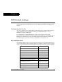
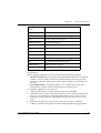
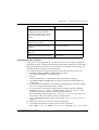
Gigabit Fiber Optic Cabling
12
Gigabit
Interface
Fiber
Type
Diameter
(µm)
Modal
Bandwidth
(MhzKm)
Maximum
Distance
(m)
Minimum
Wavelength
Distance
(nm)
(m)
1000BASE-SX
MM
62.5
160
220
2
850
1000BASE-SX
MM
62.5
200
275
2
850
1000BASE-SX
MM
50
400
500
2
850
1000BASE-SX
MM
50
500
550
2
850
1000BASE-LX
MM
62.5
500
550
2
1310
1000BASE-LX
MM
50
400
550
2
1310
1000BASE-LX
SM
9
NA
10,000
2
1310
1000BASEELX
SM
9
NA
70,000
2
1550
Avaya P332G-ML User’s Guide
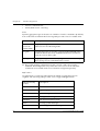
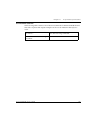
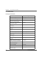
Chapter 3
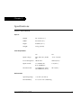
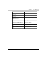
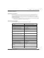
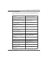
Console Pin Assignments
For direct Console communications, connect the Avaya P330 to the Console
Terminal using the supplied RJ-45 crossed cable and RJ-45 to DB-9 adapter.
Avaya P330 RJ-45 Pin
Name
(DCE View)
Terminal
DB-9 Pins
Modem
DB-25 Pins
1
For future use
NC
See note
2
TXD
(P330 input)
3
3
3
RXD
(P330 output)
2
2
4
CD
4
8
5
GND
5
7
6
DTR
1
20
7
RTS
8
4
8
CTS
7
5
L Pin 1 of the Modem DB-25 connector is internally connected to Pin 7 GND.
Avaya P332G-ML User’s Guide
13
Chapter 3
14
Avaya P332G-ML User’s Guide
SECTION 2: INSTALLATION
Chapter 4
Installation
The P332G-ML is ready to work after you complete the installation instructions
below.
Required Tools
Make sure you have the following tool at hand before undertaking the Installation
procedures:
• Phillips (cross-blade) screwdriver
Site Preparation
You can mount Avaya P330 switches alone or in a stack in a standard 19-inch
equipment rack in a wiring closet or equipment room. Up to 10 units can be stacked
in this way. When deciding where to position the unit, ensure that:
• It is accessible and cables can be connected easily and according to the
configuration rule.
• Cabling is away from sources of electrical noise such as radio transmitters,
broadcast amplifiers, power lines, and fluorescent lighting fixtures.
• Water or moisture cannot enter the case of the unit.
• There is a free flow of air around the unit and that the vents in the sides of the
case are not blocked.
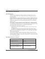
L Use Octaplane cables to interconnect with other switches.
• The environmental conditions match the requirements listed below:
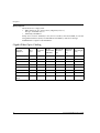
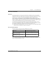
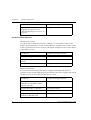
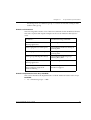
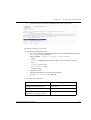
Table 4.1
Environmental Prerequisites
Operating Temp.
-5 to 50°C (23 to 122°F)
Relative Humidity
5% to 95% non-condensing
Avaya P332G-ML User’s Guide
17
Chapter 4
Installation
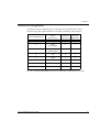
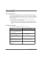
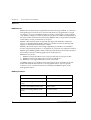
•
The power source matches the specifications listed below:
Table 4.2
Input voltage
90 to 265 VAC, 50/60 Hz
Power dissipation
100 W max
Input current
1.5 A
Table 4.3
18
Power Requirements – AC
Power Requirements – DC
Input voltage
-36 to -72 VDC
Power dissipation
100 W max
Input current
4 A max
Avaya P332G-ML User’s Guide
Chapter 4
Installation
Rack Mounting (Optional)
The P332G-ML case fits in most standard 19-inch racks. P332G-ML is 2U
(88 mm, 3.5”) high.
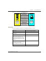
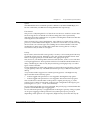
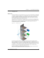
Place the P332G-ML in the rack as follows:
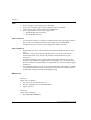
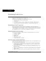
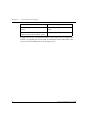
1 Snap open the ends of the front panel to reveal the fixing holes.
2 Insert the unit into the rack. Ensure that the four P332G-ML screw holes are
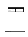
aligned with the rack hole positions as shown in Figure 4.1.
Figure 4.1
3
4
5
P332G-ML Rack Mounting
Secure the unit in the rack using the screws. Use two screws on each side. Do
not overtighten the screws.
Snap close the hinged ends of the front panel.
Ensure that ventilation holes are not obstructed.
Avaya P332G-ML User’s Guide
19
Chapter 4
Installation
Installing the X330STK-ML Stacking Sub-Module (Optional)
Caution: The stacking sub-modules contain components sensitive to electrostatic
discharge. Do not touch the circuit board unless instructed to do so.
To install the stacking sub-module in the P332G-ML:
1 Remove the blanking plate from the back of the P332GP332G-ML switch.
2 Insert the stacking sub-module gently into the slot, ensuring that the metal base
plate is aligned with the guide rails. The metal plate of the X330STK-ML (and
not the PCB) fits onto the guide rails.
3 Press the sub-module in firmly until it is completely inserted into the
P332GP332G-ML.
4 Gently turn the two screws on the side panel of the stacking sub-module until
they are secure.
L The P332GP332G-ML must not be operated with the back-slot open. The stacking
sub-module should be covered with the supplied blanking plate if necessary.
L Only use the X330STK-ML stacking module with the P332GP332G-ML.
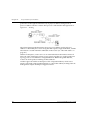
Connecting Stacked Switches
L The two ends of the Octaplane cable terminate with different connectors. Each
connector can only be connected to its matching port.
You can use the following cables to connect stacked switches:
• Short Octaplane cable (X330SC) – ivory-colored, used to connect adjacent
switches (Catalog No. CB0223) or switches separated by a BUPS unit.
• Long/Extra Long Octaplane cable (X330LC/X330L-LC) – ivory-colored, used to
connect switches from two different physical stacks, or switches separated by a
BUPS unit (Catalog No. CB0225/CB0270).
• Redundant/Long Redundant Octaplane cable (X330RC/X330L-RC) – black,
used to connect the top and bottom switches of a stack (Catalog No. CB0222/
CB0269).
These are the same cables that are used with all the P330 switches.
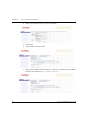
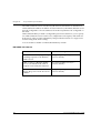
To connect stacked switches:
L When adding a module to an existing stack, first connect the stacking cables and
then power up the module.
1 Plug the light grey connector of the Short Octaplane cable into the port marked
“to upper unit” of the bottom P330 switch.
2 Plug dark grey connector of same Short Octaplane cable to the port marked “to
lower unit” in the unit above. The connections are illustrated in Figure 4.3.
3 Repeat Steps 1 and 2 until you reach the top switch in the stack.
20
Avaya P332G-ML User’s Guide
Chapter 4
4
5
Installation
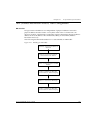
If you wish to implement stack redundancy, use the Redundant Cable to
connect the port marked “to lower unit” on the bottom switch to the port
marked “to upper unit” on top switch of the stack.
Power up the added modules.
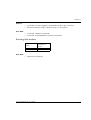
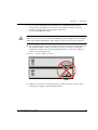
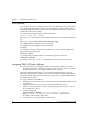
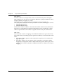
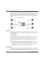
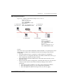
Caution: Do not cross connect two P330 switches with two Octaplane (light-colored)
cables. If you wish to cross-connect for redundancy, use one light-colored Octaplane
cable and one black redundancy cable. Figure 4.2 shows an incorrect connection.
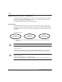
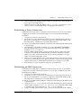
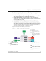
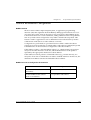
L You can build a stack of up to 10 P330 switches (any mixture of P330 and P330ML modules within a stack is possible). If you do not wish to stack all the
switches in a single rack, use long Octaplane cables to connect two physical
stacks as shown in Figure 4.3.
Figure 4.2
Incorrect Stack Connection
BUPS
Connector
Cable to
Lower Unit
Cable to
Upper Unit
Cable to
Lower Unit
Cable to
Upper Unit
Power Supply
Connector
BUPS
Connector
Power Supply
Connector
L Figures 4.2 and 4.3 show the back panel of a P330 switch AC version. These
drawings also apply to the P330-ML products.
Avaya P332G-ML User’s Guide
21
Chapter 4
Installation
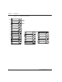
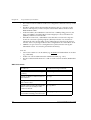
Figure 4.3
P330 Stack Connections
BUPS
Connector
BUPS
Connector
Cable to
Lower Unit
Cable to
Upper Unit
5
Power Supply
Connector
X330SC
BUPS
Connector
Cable to
Lower Unit
Cable to
Upper Unit
Cable to
Upper Unit
10
Cable to
Lower Unit
Cable to
Upper Unit
9
Cable to
Lower Unit
Cable to
Upper Unit
Cable to
Lower Unit
Cable to
Upper Unit
Cable to
Lower Unit
Cable to
Upper Unit
BUPS
Connector
4
Power Supply
Connector
Power Supply
Connector
BUPS
Connector
BUPS
Connector
Cable to
Lower Unit
Cable to
Upper Unit
3
Power Supply
Connector
8
Power Supply
Connector
BUPS
Connector
BUPS
Connector
Cable to
Lower Unit
Cable to
Upper Unit
2
Power Supply
Connector
Power Supply
Connector
BUPS
Connector
BUPS
Connector
X330RC
Power Supply
Connector
Cable to
Lower Unit
Power Supply
Connector
Cable to
Lower Unit
Cable to
Upper Unit
1
7
6
Power Supply
Connector
X330LC
22
Avaya P332G-ML User’s Guide
Chapter 4
Installation
Making Connections to Network Equipment
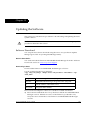
This section describes the physical connections that you can make between the
Avaya P330 switch and other network equipment.
Prerequisites
Make sure you have the following before attempting to connect network equipment
to the P330 switch:
• A list of network equipment to be connected to the P330 switch, detailing the
connector types on the various units
• All required cables (see below). Appropriate cables are available from your
local supplier.
Connecting Cables to Network Equipment
P332G-ML switches include the following types of ports (according to the speed
and standard they support): SFP GBIC
To connect the cables:
1 Insert an SFP GBIC (Small Form Factor Plugable Gigabit Interface Converter)
transceiver (not supplied) to the port housing. For a list of approved SFP GBIC
transceivers, see www.avayanetwork.com. For fiberoptic cable properties, see
Table 4.4.
L GBICs are 3.3V.
2 Connect the Ethernet fiberoptic cable (not supplied) to the GBIC transceiver on
the front panel of the Avaya P332G-ML. You can use LC or MT-RJ fiberoptic
cables depending on the GBIC transceiver you are using.
3 Connect the other end of the cable to the Ethernet port of the PC, server, router,
workstation, switch, or hub.
4 Check that the appropriate link (LNK) LED lights up.
Avaya P332G-ML User’s Guide
23
Chapter 4
Installation
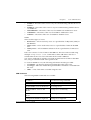
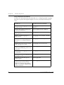
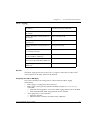
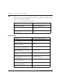
Table 4.4 displays the different types of SFP GBIC interfaces, their fiber type,
diameter, modal bandwidth, wavelengths, minimum and maximum distance.
Table 4.4
24
Gigabit Ethernet Cabling
Gigabit
Interface
Fiber
Type
Diameter
(µm)
Modal
Bandwidth
(MhzKm)
Maximum
Distance
(m)
Minimum
Wavelength
Distance
(nm)
(m)
1000BASE-SX
MM
62.5
160
220
2
850
1000BASE-SX
MM
62.5
200
275
2
850
1000BASE-SX
MM
50
400
500
2
850
1000BASE-SX
MM
50
500
550
2
850
1000BASE-LX
MM
62.5
500
550
2
1310
1000BASE-LX
MM
50
400
550
2
1310
1000BASE-LX
SM
9
NA
10,000
2
1310
1000BASE-ELX SM
9
NA
70,000
2
1550
Avaya P332G-ML User’s Guide
Chapter 5
Powering Up the Avaya P330
This section describes the procedures for powering up the Avaya P330 unit.
Powering On – Avaya P330 Module AC
For the AC input version of the Avaya P330, insert the AC power cord into the
power inlet in the back of the unit. The unit powers up.
If you are using a BUPS, insert a power cord from the BUPS into the BUPS-ML
connector in the back of the unit. The unit powers up even if no direct AC power is
applied to the unit.
After power up or reset, the Avaya P330 performs a self test procedure.
Caution: Ensure that you connect your P330-ML units to the BUPS-ML only. The
P330 BUPS is not compatible with P330-ML units.
Powering On – Avaya P330 Switch DC
For the DC input version of the Avaya P330, connect the power cable to the switch
at the input terminal block.
1 The terminals are marked “+”, “-“, and with the IEC 5019a Ground symbol.
2 The size of the three screws in the terminal block is M3.5.
3 The pitch between each screw is 9.5mm.
Connect the power cable to the DC power supply. After power up or reset, the
Avaya P330 performs a self test procedure.
Warning: Before performing any of the following procedures, ensure that DC power
is OFF.
Caution: This product is intended for installation in restricted access areas and is
approved for use with 18 AWG copper conductors only. The installation must
comply with all applicable codes.
Avaya P332G-ML User’s Guide
25
Chapter 5
Powering Up the Avaya P330
Warning: The proper wiring sequence is ground to ground, positive to positive and
negative to negative. Always connect the ground wire first and disconnect it last.
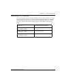
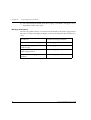
Post-Installation
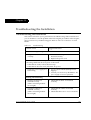
The following indicate that you have performed the installation procedure
correctly:
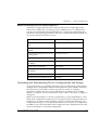
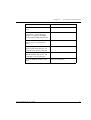
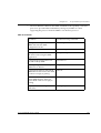
Table 5.1
Post-Installation Indications
Troubleshooting
Information
Procedure
Indication
Powering the P330
All front panel LEDs illuminate
briefly.
Page 143
Creating Stacks
The LED next to the
appropriate connection (“Cable
to upper unit” or “Cable to
lower unit”) is lit.
Page 143
If you do not receive the appropriate indication, please refer to “Troubleshooting
the Installation“.
26
Avaya P332G-ML User’s Guide
Chapter 6
Avaya P332G-ML Front and Rear Panels
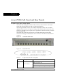
Avaya P332G-ML Front Panel
The P332G-ML front panel contains LEDs, controls, and connectors. The status
LEDs and control buttons provide at-a-glance information.
The front panel LEDs consist of Port LEDs and Function LEDs. The Port LEDs
display information for each port according to the illuminated function LED. The
function is selected by pressing the left or right button until the desired parameter
LED is illuminated.
The P332G-ML front panel shown below includes LEDs, buttons, SFP GBIC
transceiver housings and the RJ-45 console connector. The LEDs are described in
Table 6.1.
Figure 6.1
P332G-ML Front Panel
Figure 6.2
P332G-ML LEDs
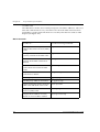
Table 6.1
Avaya P332G-ML LED Descriptions
LED Name
Description
LED Status
OFF – Power is off
PWR
Power Status
ON – Power is on
Blink – Using BUPS-ML power only
Avaya P332G-ML User’s Guide
27
Chapter 6
Avaya P332G-ML Front and Rear Panels
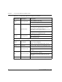
Table 6.1
Avaya P332G-ML LED Descriptions (Continued)
LED Name
Description
OPR
CPU Operation
LED Status
OFF – Module is booting
ON – Normal operation
OFF – Module is a slave in a stack
SYS
System Status
ON – Module is the master of the stack and
the Octaplane and Redundant (optional)
cable(s) are connected correctly.
This LED will also light in Standalone mode.
Blink – Box is the master of the stack and the
Octaplane is in redundant mode.
ROUT
Routing Mode
OFF – Layer 2 mode
ON – Router mode
The following Function LEDs apply to all ports
LNK
Port Status
ON – Link is OK
OFF – Port is disabled
Blink – Port is enabled, but Link is down
COL
Collision
Always OFF. All ports are full-duplex only.
OFF – No transmit activity
Tx
Transmit to line
ON – Data transmitted on line from the
module
OFF – No receive activity
28
Rx
Receive from line
ON – Data received from the line into the
module
FDX
Full Duplex mode
Always ON. All ports are full-duplex only.
Avaya P332G-ML User’s Guide
Chapter 6
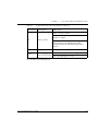
Table 6.1
Avaya P332G-ML Front and Rear Panels
Avaya P332G-ML LED Descriptions (Continued)
LED Name
Description
LED Status
OFF – No flow control.
ON – One of the three possible flow control
modes is enabled.
FC
Flow Control
Hspd
High Speed
Always ON – 1000 Mpbs mode only
LAG
Link Aggregation
Group (Trunking)
OFF – No LAG defined for this port
Note: FC LED for Gigabit Ethernet ports
reflect the last negotiated mode when
autonegotiation is enabled and the link is
down.
ON – Port belongs to a LAG
L All LEDs are lit during reset.
Avaya P332G-ML User’s Guide
29
Chapter 6
Avaya P332G-ML Front and Rear Panels
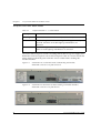
Avaya P332G-ML Back Panel
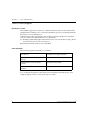
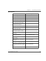
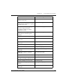
Table 6.2
Avaya P332G-ML <- -> Select buttons
Description
Function
Left/Right
Individual – select LED function (see table above)
Reset module
Press both right and left buttons together for approximately 2
seconds. All LEDs on module light up until buttons are
released.
Reset stack
Press both Right and Left buttons together for 4 seconds. All
LEDs on stack light up until buttons are released.
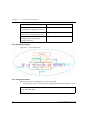
The P332G-ML back panel contains a Stacking Sub-module slot, power supply and
BUPS-ML connector. Figure 6.3 shows the back panel of the AC version switch and
Figure 6.4 shows the back panel of the DC version switch with a stacking submodule installed.
30
Figure 6.3
P332G-ML AC version Back Panel (with Stacking Sub-module,
BUPS-ML connector cover plate removed)
Figure 6.4
P332G-ML DC Back Panel (without Stacking Sub-module installed,
BUPS-ML connector cover plate shown)
Avaya P332G-ML User’s Guide
Chapter 6
Avaya P332G-ML Front and Rear Panels
BUPS-ML Input Connector
The BUPS-ML input connector is a 3.3 VDC and 5 VDC connector for use with the
P330 BUPS-ML unit only. A BUPS Input sticker appears directly above the
BUPS-ML input connector, which is covered with a metal plate.
Figure 6.5
BUPS-ML Input Connector Sticker
Avaya P332G-ML User’s Guide
31
Chapter 6
32
Avaya P332G-ML Front and Rear Panels
Avaya P332G-ML User’s Guide
Chapter 7
Establishing Switch Access
This chapter describes various methods for accessing the Avaya P330 CLI and
logging in with the appropriate security level.
Methods for accessing the Avaya P330 CLI include using:
• a terminal to the serial port on the switch
• P330 Sessions
• a workstation running a Telnet or SSH session connected via the network
• a remote terminal/workstation attached via a modem (PPP connection)
Establishing a Serial Connection
This section describes the procedure for establishing switch access between a
terminal and the Avaya P330 switch over the serial port provided on the front panel
of the P330 (RJ-45 connector labeled “Console”). For information on the console port
pin assignments, refer to “Console Pin Assignments“ on page 13.
Configuring the Terminal Serial Port Parameters
The serial port settings for using a terminal or terminal emulator are as follows:
• Baud Rate - 9600 bps
• Data Bits - 8 bits
• Parity - None
• Stop Bit - 1
• Flow Control - None
• Terminal Emulation - VT-100
Connecting a Terminal to the Avaya P330 Serial port
Perform the following steps to connect a terminal to the Avaya P330 Switch Console
port for accessing the text-based CLI:
1 The P330 device is supplied with a console cable and a RJ-45-to-DB-9 adaptor.
Use these items to connect the serial (COM) port on your PC/terminal to the
Avaya P330 console port.
2 Ensure that the serial port settings on the terminal are 9600 baud, 8 bits, 1 stop
bit and no parity.
3 When you are prompted for a Login Name, enter the default login. The default
login is root.
4 When you are promoted for a password, enter the user level password root.
Avaya P332G-ML User’s Guide
33
Chapter 7
Establishing Switch Access
P330 Sessions
You can use sessions to switch between the CLI of P330 modules, other stack entities
(for example, an X330 ATM or WAN entity plugged into a specific P330 switch or
with the G700 Media Gateway Processor), or to switch between Layer 2 and Layer 3
commands in the router module.
To switch between P330 modules use the command:
session [<mod_num>] <mode>.
The <mod_num> is the number of the module in the stack, counting from the bottom
up.
The <mode> can be either switch, router, wan, atm, mgp.
Use switch mode to configure layer 2 commands.
Use router mode to configure routing commands.
Examples:
To configure router parameters in the module that you are currently logged into,
type the following command:
session router.
To configure the switch parameters, on module 6, type the command:
session 6 switch.
L When you use the session command the security level stays the same.
Assigning P330’s IP Stack Address
L All P330 switches are shipped with the same default IP address. You must
change the IP address of the master P330 switch in a stack in order to guarantee
that the stack has its own unique IP address in the network.
The network management station or a workstation running Telnet session can
establish communications with the stack once this address had been assigned and
the stack has been inserted into the network. Use the CLI to assign the P330 stack an
IP address and net mask.
To assign a P330 IP stack address:
1 Establish a serial connection by connecting a terminal to the Master P330 switch
of the stack.
2 When prompted for a Login Name, enter the default name root
3 When you are prompted for a password, enter the password root. You are
now in Supervisor Level.
4 At the prompt, type:
set interface inband <vlan> <ip_address> <netmask>
Replace <vlan>, <ip_address> and <netmask> with the VLAN,
IP address, and net mask of the stack.
5 Press Enter to save the IP address and net mask.
34
Avaya P332G-ML User’s Guide
Chapter 7
6
7
Establishing Switch Access
At the prompt, type reset and press Enter to reset the stack. After the Reset,
log in again as described above.
At the prompt, type set ip route <dest> <gateway> and replace <dest>
and <gateway> with the destination and gateway IP addresses.
Establishing a Telnet Connection
Perform the following steps to establish a Telnet connection to the Avaya P330 for
configuration of Stack or Router parameters. You can Telnet the Stack Master
IP address:
1 Connect your station to the network.
2 Verify that you can communicate with the Avaya P330 using Ping to the IP of
the Avaya P330. If there is no response using Ping, check the IP address and
default gateway of both the Avaya P330 and the station.
L The Avaya P330 default IP address is 149.49.32.134 and the default subnet mask
is 255.255.255.0.
3 From the Microsoft Windows taskbar of your PC click Start and then Run (or
from the DOS prompt of your PC), then start the Telnet session by typing:
telnet <P330_IP_address>
If the IP Address in the Telnet command is the IP address of the stack, then
connection is established with the Switch CLI entity of the Master module.
When you see the “Welcome to P330” menu and are prompted for a Login
Name, enter the default name root
4 When you are prompted for a password, enter the User Level password root
in lower case letters (do NOT use uppercase letters). The User level prompt will
appear when you have established communications with the Avaya P330.
5 Press Enter to save the destination and gateway IP addresses.
Establishing an SSH Connection
Perform the following steps to establish an SSH connection to the Avaya P330 for
configuration of Stack or Router parameters. You can open an SSH session to the
Stack Master IP address:
1 Connect your station to the network.
2 Verify that you can communicate with the Avaya P330 using Ping to the IP of
the Avaya P330. If there is no response using Ping, check the IP address and
default gateway of both the Avaya P330 and the station.
L The Avaya P330 default IP address is 149.49.32.134 and the default subnet mask
is 255.255.255.0.
3 Using the show ip ssh command, ensure that an SSH key has been generated
on the switch using the crypto key generate dsa command and that SSH
is enabled on the switch using the ip ssh enable command.
4 Using your SSH client software, open a session to the Stack Master IP address.
Avaya P332G-ML User’s Guide
35
Chapter 7
Establishing Switch Access
5
When you are prompted for a password, enter the User Level password root
in lower case letters (do NOT use uppercase letters). The User level prompt will
appear when you have established communications with the Avaya P330.
Establishing a Modem (PPP) Connection with the P330
Overview
Point-to-Point Protocol (PPP) provides a Layer 2 method for transporting
multi-protocol datagrams over modem links.
Connecting a Modem to the Console Port
A PPP connection with a modem can be established only after the Avaya P330 is
configured with an IP address and net-mask, and the PPP parameters used in the
Avaya P330 are compatible with the modem’s PPP parameters.
1 Connect a terminal to the console port of the Avaya P330 switch as described in
Connecting a Terminal to the Avaya P330 Serial port.
2 When you are prompted for a Login Name, enter the default name root.
3 When you are prompted for a password, enter the password root. You are
now in Supervisor Level.
4 At the prompt, type:
set interface ppp <ip_addr> <net-mask>
with an IP address and netmask to be used by the Avaya P330 to connect via its
PPP interface.
L The PPP interface configured with the set interface ppp command must
be on a different subnet from the stack inband interface.
5 Set the baud rate, ppp authentication, and ppp time out required to match your
modem. These commands are described in the Avaya P330: Reference Guide.
6 At the prompt, type:
set interface ppp enable
The CLI responds with the following:
Entering the Modem mode within 60 seconds...
7
8
9
36
Please check that the proprietary modem cable is plugged
into the console port
Use the DB-25 to RJ-45 connector to plug the console cable to the modem’s
DB-25 connector. Plug the other end of the cable RJ-45 connector to the
Avaya P330 console’s RJ-45 port.
The Avaya P330 enters modem mode.
You can now dial into the switch from a remote station, and open a Telnet
session to the PPP interface IP address.
Avaya P332G-ML User’s Guide
Chapter 7
Establishing Switch Access
Security Levels
There are four security access levels – User, Privileged, Configure, and Supervisor.
• The User level (‘read-only’) is a general access level used to show system
parameter values.
• The Privileged level (‘read-write’) is used by site personnel to access stack
configuration options.
• The Configure level is used by site personnel for Layer 3 configuration.
• The Supervisor level (‘administrator’) is used to define user names, passwords,
and access levels of up to 10 local CLI users, configure SNMPv3, configure
RADIUS authentication, and control access protocols to the device.
L If you wish to define more than ten users per switch, or accounts for a user on
multiple switches, use RADIUS (Remote Authentication Dial-In User Service).
A login name and password are always required to access the CLI and the
commands. The login name, password, and access-type (i.e., security level) for a
user account are established using the username command.
Switching between the entities, does not effect the security level since security levels
are established specifically for each user. For example, if the operator with a
privileged security level in the Switch entity switches to the Router entity the
privileged security level is retained.
L If you wish to increase security, you can change the default user accounts and
SNMP communities.
L The Web management passwords are the same as those of the CLI. If you
change the passwords of the CLI then those passwords become active for Web
management as well.
Entering the Supervisor Level
The Supervisor level is the level in which you first enter P330 CLI and establish user
names for up to 10 local users. When you enter the Supervisor level, you are asked
for a Login name. Type root as the Login name and the default password root
(in lowercase letters):
Welcome to P330
Login: root
Password:****
Password accepted.
Cajun_P330-N(super)#
Avaya P332G-ML User’s Guide
37
Chapter 7
Establishing Switch Access
Defining new local users
Define new users and access levels using the following command in Supervisor
Level:
In order to...
Use the following command...
Add a local user account and
configure a user (name, password
and access level)
username
To remove a local user account
no username
Display the username, password
and access type for all users on the
switch
show username
Exiting the Supervisor Level
To exit the Supervisor level, type the command exit.
Entering the CLI
To enter the CLI, enter your username and password. Your access level is indicated
in the prompt as follows:
The User level prompt is shown below:
Cajun_P330-N>
The Privileged level prompt is shown below:
Cajun_P330-N#
The Configure level prompt for Layer 3 configuration is shown below:
P330-N(configure)#
The Supervisor level prompt is shown below:
Cajun_P330-N(super)#
38
Avaya P332G-ML User’s Guide
Chapter 8
User Authentication
Introduction
A secure system provides safeguards to insure that only authorized personnel can
perform configuration procedures. In Avaya P330, these safeguards form part of the
CLI architecture and control remote access via SNMP, Telnet, and SSH. In addition,
you can block any of the IP protocols supported by the P330.
SNMP Support
Introduction to SNMP
SNMP Versions
There are currently three versions of (Simple Network Management Protocol)
SNMP:
• SNMPv1
• SNMPv2c
• SNMPv3
The P330 supports device access using all three versions of SNMP.
Managers and Agents
SNMP uses software entities called managers and agents to manage network
devices. The manager monitors and controls all other SNMP-managed devices or
network nodes on the network. There must be at least one SNMP Manager in a
managed network. The manager is installed on a workstation located on the
network.
An agent resides in a managed device or network node. The agent receives
instructions from the SNMP Manager, generates reports in response to requests
from the SNMP Manager, and also sends management information back to the
SNMP Manager as events occur. Every P330 module has an agent. However, on
each P330 stack, one module is selected to be the master module. The stack is
managed via the master module’s agent.
There are many SNMP management applications, but all these applications perform
the same basic task. They allow SNMP managers to communicate with agents to
configure, get statistics and information, and receive alerts from network devices.
You can use any SNMP-compatible network management system to monitor and
Avaya P332G-ML User’s Guide
39
Chapter 8
User Authentication
control the P330.
Manager/Agent Communication
There are several ways that the SNMP manager and the agent communicate.
The manager can:
• Retrieve a value – a get action
The SNMP manager requests information from the agent, such as the link status
of an Ethernet port or the number of good packets received on the switch. The
agent gets the value of the requested MIB variable and sends the value back to
the manager.
• Retrieve the value immediately after the variable you name – a get-next action.
The SNMP manager retrieves values from the MIB tree. Using the get-next
function, you do not need to know the exact variable name you are looking for.
The SNMP manager takes the variable you name and then uses a sequential
search to find the desired variable.
• Retrieve a number of values – a get-bulk action
The get-bulk operation retrieves the specified number of instances of the
requested MIB variable. This minimizes the number of protocol exchanges
required to retrieve a large amount of data.
L Get-bulk is not supported in SNMPv1.
• Change a setting on the agent – a set action
The SNMP manager requests the agent to change the value of the MIB variable.
For example, you can enable or disable a port.
• An agent can send an unsolicited message to the manager at any time if a
significant, predetermined event takes place on the agent. This message is called
a trap.
When a trap condition occurs, the SNMP agent sends an SNMP trap message to
the specified trap receiver or trap host. The SNMP Administrator configures the
trap host, usually the SNMP management station, to perform the action needed
when a trap is detected.
SNMPv1
SNMPv1 uses community strings to limit access rights. Each SNMP device is
assigned to a read community and a write community. To communicate with a
switch, you must send an SNMP packet with the relevant community name.
By default, if you communicate with a switch using only the read community, you
are assigned the security name ’ReadCommN’. This security name is mapped to
the ’ReadCommG’ group by default. This allows you to view the agent’s MIB tree,
but cannot change any of the values in the MIB tree.
If you communicate with a switch using the write community, you are assigned the
security name ’WriteCommN’. This security name is mapped to the
40
Avaya P332G-ML User’s Guide
Chapter 8
User Authentication
’WriteCommG’ group by default. This allows you to view the agent’s MIB tree and
change any of the values in the MIB tree.
L If you delete the ReadCommN or WriteCommN users, the ReadCommG or
WriteCommG groups, or the SNMPv1View you may not be able to access the
switch using SNMPv1 or SNMPv2c.
In addition, traps are sent to designated trap receivers. Packets with trap
information also contains a trap community string.
SNMPv2c
SNMPv2c is very similar to SNMPv1. However, SNMPv2c adds support for the
get-bulk action and supports a different trap format.
SNMPv3
SNMPv3 enables the following features over SNMPv1 or v2c:
• User authentication with a username and password.
• Communication encryption between the Network Management Station (NMS)
and the SNMP agent at the application level
• Access control definition for specific MIB items available on the SNMP agent
• Notification of specified network events directed toward specified users
• Definition of roles using access control, each with unique access permissions
and authentication/encryption requirements
The basic components in SNMPv3 access control are users, groups, and views.
In addition. SNMPv3 uses an SNMP engine ID to identify SNMP identity. An
SNMP engine ID is assigned to each IP address of each device in the network. Each
SNMP engine ID should be unique in the network.
Users
SNMPv3 uses the User-based Security Model (USM) for security, and the
View-based Access Control Model (VACM) for access control. USM uses the
HMAC-MD5-96 and HMAC-SHA-96 protocols for user authentication, and the
CBC-DES56 protocol for encryption or privacy.
A maximum of 21 users, including local users and remote users getting notifications
can be defined on a stack. If the SNMP engine ID changes, all users other than the
default user for the stack are invalid and must be redefined. The SNMP engine ID
can be changed via the CLI. In addition, a change in the IP address of the stack
automatically changes the SNMP engine ID.
SNMPv3 supports three security levels:
• NoAuthNoPriv – This is the lowest level of SNMPv3 security. No (Message
Authentication Code) MAC is provided with the message, and no encryption is
performed. This method is maintains the same security level as SNMPv1, but
provides a method for limiting the access rights of a user.
Avaya P332G-ML User’s Guide
41
Chapter 8
User Authentication
•
•
AuthNoPriv – User authentication is performed based on MD5 or SHA
algorithms. The message is sent with an HMAC that is calculated with the user
key. The data part is sent unencrypted.
AuthPriv – User authentication is performed based on MD5 or SHA algorithms.
The message is sent in encrypted MAC that is calculated with the user key, and
the data part is sent with DES56 encryption using the user key.
To create an SNMPv3 user account, the following information must be provided:
• UserName – string representing the name of the user.
Maximum length: 32 characters.
• Authentication Protocol – The authentication protocol to use. Possible values
are: No auth, HMAC MD5, or HMAC SHA-1.
• Authentication Password – The authentication password is transformed using
the authentication protocol and the SNMP engine ID to create an authentication
key.
• Privacy Protocol – The privacy protocol to use. Possible values are: No privacy,
DES privacy.
• Privacy Password – The privacy password is transformed using the privacy
protocol and the SNMP engine ID to create a privacy key.
• GroupName – 32 character string representing the name of the group.
• SecurityModel – The security model to use. Possible values are: 1 (SNMPv1),
2 (SNMPv2c), 3 (USM).
Groups
In SNMPv3, each user is mapped to a group. The group maps its users to defined
views. These views define sets of access rights, including read, write, and trap or
inform notifications the users can receive.
The group maps its users to views based on the security mode and level with which
the user is communicating with the switch. Within a group, the following
combinations of security mode and level can be mapped to views:
• SNMPv1 – Anyone with a valid SNMPv1 community name.
• SNMPv2c – Anyone with a valid SNMPv2c community name.
• NoAuthNoPriv – An SNMPv3 user using the NoAuthNoPriv security level.
• AuthNoPriv – An SNMPv3 user using the AuthNoPriv security level.
• AuthPriv – An SNMPv3 user using the AuthPriv security level.
If views are not defined for all security modes and levels, a user can access the
highest level view below his security level. For example, if the SNMPv1 and
SNMPv2c views are undefined for a group, anyone logging in using SNMPv1 and
SNMPv2c cannot access the device. If the NoAuthNoPriv view is not defined for a
group, SNMPv3 users with a NoAuthNoPriv security level can access the SNMPv2c
view.
To create an SNMPv3 group, the following information must be provided:
• GroupName – 32 character string representing the name of the group.
42
Avaya P332G-ML User’s Guide
Chapter 8
•
•
•
•
•
User Authentication
SNMPv1 – The name of the view for anyone communicating with the device via
SNMPv1.
SNMPv2c – The name of the view for anyone communicating with the device
via SNMPv2c.
NoAuthNoPriv – The name of the view for SNMPv3 NoAuthNoPriv users.
AuthNoPriv – The name of the view for SNMPv3 AuthNoPriv users.
AuthPriv – The name of the view for SNMPv3 AuthPriv users.
Views
There are three types of views:
• Read Views – Allow read-only access to a specified list of Object IDs (OIDs) in
the MIB tree.
• Write Views – Allow read-write access to a specified list of OIDs in the MIB
tree.
• Notify Views – Allow SNMP notifications from a specified list of OIDs to be
sent.
Each view consists of a list of OIDs in the MIB tree. This list can be created using
multiple “snmp-server view” commands to either add OIDs to the list or
exclude OIDs from a list of all of the OIDs in the switch’s MIB tree.
You can use wildcards to include or exclude an entire branch of OIDs in the MIB
tree, using an asterisk instead of the specific node.
To create an SNMPv3 view, the following information must be provided:
• ViewName – 32 character string representing the name of the view.
• ViewType – Indicates whether the specified OID is included or excluded from
the view.
• OIDs – A list of the OIDs accessible using the view.
SNMP Commands
The following SNMP commands are available.
In order to...
Use the following command...
Enable SNMP access to the device
snmp-server enable
Disable SNMP access to the device
no snmp-server
Enable SNMPv1 access to the
device
snmp-server community
Disable SNMPv1 access to the
device
no snmp-server community
Configure the SNMPv3 engine ID
snmp-server engineID
Avaya P332G-ML User’s Guide
43
Chapter 8
44
User Authentication
In order to...
Use the following command...
Return the SNMPv3 engine ID to its
default
no snmp-server engineID
Create an SNMPv3 user
snmp-server user
Remove an SNMPv3 user
no snmp-server user
Create an SNMPv3 group
snmp-server group
Remove an SNMPv3 group
no snmp-server group
Create a view or add or exclude
OIDs from a view
snmp-server view
Delete an SNMPv3 view
no snmp-server view
Set a read/write/trap SNMPv1
community name
set snmp community
Display a list of SNMPv3 views
show snmp view
Display a table of SNMPv3 users
and the groups with which they are
mapped
show snmp userToGroup
Display the SNMPv3 engine ID
show snmp engineID
Display a list of SNMPv3 groups
show snmp group
Display a list of SNMPv3 users
show snmp user
Display a list of SNMPv3
notification receivers and SNMPv1
trap receivers
show snmp
Enable or disable link up/link
down notifications and traps
set port trap
Define SNMPv1 trap receivers or
configure the SNMPv1 traps sent
by the device
set snmp trap
Removes SNMPv1 trap receivers
clear snmp trap
Enable or disable SNMPv1 traps for
authentication failures
set snmp trap enable/disable auth
Avaya P332G-ML User’s Guide
Chapter 8
User Authentication
In order to...
Use the following command...
Enable SNMP notifications (traps
and inform)
snmp-server enable notifications
Disable SNMP notifications (traps
and inform)
no snmp-server notifications
Create an SNMPv3 remote user for
SNMP notifications
snmp-server remote-user
Remove an SNMPv3 remote user
for SNMP notifications
no snmp-server remote-user
Configure the SNMPv3 timeout
and retries for notifications
snmp-server informs
Define an SNMPv3 notification
host
snmp-server host
Remove an SNMPv3 notification
host
no snmp-server host
Avaya P332G-ML User’s Guide
45
Chapter 8
User Authentication
SSH Protocol Support
Introduction to SSH
SSH (Secure Shell) protocol is a security protocol that enables establishing a remote
session over a secured tunnel, also called a remote shell. SSH accomplishes this by
creating a transparent encrypted channel between the local and remote devices. In
addition to remote shell, SSH also provides secure file transfer between the local
and remote devices.
SSH uses password authentication.
A maximum of two SSH sessions can be active per router module in the stack, with
two additional active SSH sessions per stack. For example, if a stack contains three
router modules, a maximum of eight SSH sessions can be active on the stack.
The P330 agent reports SSH sessions opened to it. In addition, each router module
reports the SSH sessions opened to its router interface. The user can disconnect
selected SSH sessions.
The SSH session-establishment process is divided into the following stages, as
shown in Figure 8.1:
• SSH client connection:
— The P330 generates a key of variable length (512-2048 bits) using the DSA
encryption method. This is the private key.
— The P330 calculates an MD5 Hash of the public key, called a fingerprint. The
fingerprint is always 16 bytes long. This fingerprint is displayed.
— The P330 sends the public key (i.e., the fingerprint,) to the client computer.
This public key is used by the client to encrypt the data it sends to the P330.
The P330 decrypts the data using the private key.
— Both sides negotiate and must agree on the same chipper type. The P330
only supports 3DES-CBC encryption. The user on the client side accepts the
fingerprint. The client keeps an IP vs. fingerprint public key cache and
notifies the user if the cache changes.
— The client chooses a random number that is used to encrypt and decrypt the
information sent.
— This random number is sent to the P330, after encryption based on the
P330’s public key.
— When the P330 receives the encrypted random number, it decrypts it using
the private key. This random number is now used with the 3DES-CBC
encryption method for all encryption and decryption of data. The public
and private keys are no longer used.
• User Authentication:
— Before any data is transferred, the P330 requires the client to supply a user
name and password. This authenticates the user on the client side to the
P330.
46
Avaya P332G-ML User’s Guide
Chapter 8
Figure 8.1
User Authentication
SSH Session Establishment Process
SSHClientConnection
Device Dom ain
Host Dom ain
Establish Connection
Public Key and Encryptions List
Private Key and Encryptions List
SSH Client
Acknow ledgment (ACK)
SSH Server
Username
List
Host RSA
key
User Authentication
User Passw ords
Hostnames
List
Initiate CLI Session
SSH Commands
The following SSH commands are accessible from Supervisor level.
In order to...
Use the following command...
Enable SSH and configure SSH
parameters
ip ssh enable
Disable the SSH server
no ip ssh
Display active SSH sessions on the
device. This command is only
available from the master module
switch context and from all router
contexts.
show ip ssh
Disconnect an existing SSH session.
If an SSH session was entered from
the router, it can only be
disconnected from router mode.
disconnect ssh
Generate an SSH host key pair
crypto key generate dsa
Avaya P332G-ML User’s Guide
47
Chapter 8
User Authentication
SCP Protocol Support
In addition to data transfer via an SSH session, the SSH protocol is also used to
support SCP for secure file transfer. When using SCP, the P330 is the client, and an
SCP server must be installed on the management station. After defining users on the
SCP server, the device acts as an SCP client.
The procedure described in the “Introduction to SSH“ on page 46 is used with the
roles of the P330 and the client computer reversed.
To accomplish secured transfers, a P330 launches a local SSH client via the CLI in
order to establish a secured channel to the secured file server. The P330
authenticates itself to the server by providing a user name and password. With a
Windows-based SSH server (WinSSHD), the user name provided must be a defined
user on the Windows machine with read/write privileges. The files transferred via
SCP are saved in the “C:\Documents and Settings\username” directory.
The network element performs file transfer in unattended mode.
L The P330 doesn't block SCP traffic from users not on the allowed managers list,
because it is the SSH client. In addition, the P330 doesn't prompt the user to
accept the Server’s fingerprint nor warns the user if the fingerprint from an IP
address has changed.
For information on SCP file transfer commands, refer to “Uploading and
Downloading Device Configurations and Images“on page 63.
48
Avaya P332G-ML User’s Guide
Chapter 8
User Authentication
RADIUS
Introduction to RADIUS
User accounts are typically maintained locally on the switch. Therefore, if a site
contains multiple Avaya Switches, it is necessary to configure each switch with its
own user accounts. Additionally, if for example a 'read-write' user has to be
changed into a 'read-only' user, you must change all the 'read-write' passwords
configured locally in every switch, in order to prevent him from accessing this level.
This is obviously not effective management. A better solution is to have all of the
user login information kept in a central location where all the switches can access it.
P330 features such a solution: the Remote Authentication Dial-In User Service
(RADIUS).
A RADIUS authentication server is installed on a central computer at the customer's
site. On this server user authentication (account) information is configured that
provides various degrees of access to the switch. The P330 will run as a RADIUS
client. When a user attempts to log into the switch, if there is no local user account
for the entered user name and password, then the switch will send an
Authentication Request to the RADIUS server in an attempt to authenticate the user
remotely. If the user name and password are authenticated, then the RADIUS server
responds to the switch with an Authentication Acknowledgement that includes
information on the user's privileges ('administrator', 'read-write', or 'read-only'),
and the user is allowed to gain access to the switch. If the user is not authenticated,
then an Authentication Reject is sent to the switch and the user is not allowed access
to the switch's embedded management.
The Remote Authentication Dial-In User Service (RADIUS) is an IETF standard
(RFC 2138) client/server security protocol. Security and login information is stored
in a central location known as the RADIUS server. RADIUS clients, such as the P330,
communicate with the RADIUS server to authenticate users.
All transactions between the RADIUS client and server are authenticated through
the use of a “shared secret” which is not sent over the network. The shared secret is
an authentication password configured on both the RADIUS client and its RADIUS
servers. The shared secret is stored as clear text in the client’s file on the RADIUS
server, and in the non-volatile memory of the P330. In addition, user passwords are
sent between the client and server are encrypted for increased security.
Avaya P332G-ML User’s Guide
49
Chapter 8
User Authentication
Figure 8.2 illustrates the RADIUS authentication procedure:
Figure 8.2
RADIUS Authentication Procedure
User attempts login
Local User
account
authenticated in
switch?
No
Authentication
request sent to
RADIUS Server
User name and
password
authenticated?
Yes
Yes
No
Authentication Reject
sent to switch
User cannot access switch
embedded managegment
50
Perform log-in according
to user's priviliege level
to switch
Avaya P332G-ML User’s Guide
Chapter 8
User Authentication
Radius Commands
The following RADIUS commands are accessible from Supervisor level.
In order to...
Use the following command...
Enable or disable authentication for
the P330 switch. RADIUS
authentication is disabled by
default
set radius authentication
Set a primary or secondary
RADIUS server IP address
set radius authentication server
Configure a character string to be
used as a “shared secret” between
the switch and the RADIUS server
set radius authentication secret
Set the RFC 2138 approved UDP
port number.
set radius authentication udp-port
Set the number of times an access
request is sent when there is no
response
set radius authentication
retry-number
Set the time to wait before
re-sending an access request
set radius authentication retry-time
Remove a primary or secondary
RADIUS authentication server
clear radius authentication server
Display all RADIUS authentication
configurations. Shared secrets are
not displayed.
show radius authentication
For a complete description of the RADIUS CLI commands, including syntax and
output examples, refer to Avaya P330: Reference Guide.
Avaya P332G-ML User’s Guide
51
Chapter 8
User Authentication
Telnet Client Support
Introduction to Telnet
The P330ML supports invocation of a Telnet client from the CLI. The Telnet client
implementation enables you to control the destination port for connecting daemons
that listen on a non-default port.
Authentication when connecting to the switch via Telnet is identical to standard
console connection authentication (local or RADIUS).
L Enabling and disabling the Telnet-client service can only be done using a direct
console connection via the Console port.
By default the Telnet-client service is disabled.
Telnet Commands
The following Telnet commands are available.
In order to...
Use the following command...
Open a Telnet session to another
device.
telnet
Enable Telnet access from the
switch
ip telnet-client enable
Disable Telnet access from the
switch
no ip telnet-client
For a complete description of the Telnet CLI commands, including syntax and
output examples, refer to Avaya P330: Reference Guide.
52
Avaya P332G-ML User’s Guide
Chapter 8
User Authentication
Recovery Password
Introduction
The P330 provides a recovery password in the event that you have forgotten the
login password for the switch. The recovery password feature enables you to login
to the device in a super user mode and change the regular login password.
The recovery password feature can be disabled preventing unauthorized user to
login to the device using the recovery password. However, if the recovery password
feature is disables and you forget the login password, it will not be possible to log in
to the switch. By default the recovery password feature is enabled.
To use the recovery password feature, you must connect to the switch’s console
port. Log in using the user name “root” and password “ggdaseuaimhrke”. Use the
set username command to change the password for the user “root”.
L Enabling and disabling the Recovery Password protocol can only be done using
a direct console connection via the Console port.
Recovery Password Commands
The following recovery password commands are available.
In order to...
Use the following command...
Enable the recovery password
feature on the switch
terminal recovery password enable
Disable the recovery password
feature on the switch
no terminal recovery password
For a complete description of the recovery password commands, including syntax,
refer to Avaya P330: Reference Guide.
Avaya P332G-ML User’s Guide
53
Chapter 8
User Authentication
Allowed Managers
Allowed Managers Introduction
With the Allowed Managers feature, the network manager can determine who may
or may not gain management access to the switch. The feature can be enabled or
disabled (default is disabled). When enabled, only those users that are configured in
the Allowed Managers table are able to gain Telnet, HTTP, and SNMP management
access to the switch.
You can configure up to 20 Allowed Managers by adding or removing their
IP address from the Allowed Managers List.
L The identification of an “Allowed Manager” is done by checking the Source
IP address of the packets. Thus, if the Source IP address is modified on the way
(NAT, Proxy, etc.), even an “Allowed Manager” will not be able to access the
P330.
Allowed Managers CLI Commands
The following Allowed Managers commands are available.
54
In order to...
Use the following command...
When set to enabled - only
managers with IP address specified
in the allowed table will be able to
access the device
set allowed managers
Add/delete IP address of manager
to/from the allowed table
set allowed managers ip
Show the IP addresses of the
managers that are allowed to access
the device
show allowed managers table
Show whether the status of allowed
managers is enabled or disabled
show allowed managers status
Show the IP addresses of the
managers that are currently
connected
show secure current
Avaya P332G-ML User’s Guide
Chapter 8
User Authentication
Allowed Protocols
Allowed Protocols Introduction
With the Allowed Protocols feature, the network manager can determine the IP
protocols enabled on the switch. This feature can be used to block access to the
switch using specific IP protocols. Each protocol can be independently enabled or
disabled on the switch.
L Enabling and disabling the Recovery Password protocol can only be done using
a direct console connection via the Console port.
Allowed Protocols CLI Commands
The following Allowed Protocols commands are available.
In order to...
Use the following command...
Enable Telnet on the switch
ip telnet enable
Disable Telnet on the switch
no ip telnet
Enable HTTP on the switch
ip http enable
Disable HTTP on the switch
no ip http
Enable the switch agent to accept
ICMP redirect packets sent to it
ip icmp redirect
Enable the switch agent to ignore
ICMP redirect packets sent to it
no icmp redirect
Enable SNMP on the switch
snmp-server
Disable SNMP on the switch
no snmp-server
Enable SNMPv1 switch access
snmp-server community
Disable SNMPv1 switch access
no snmp-server community
Enable SSH on the switch
ip ssh enable
Disable SSH on the switch
no ip ssh
Enable Recovery Password on the
switch
terminal recovery password enable
Disable Recovery Password on the
switch
no terminal recovery password
Avaya P332G-ML User’s Guide
55
Chapter 8
56
User Authentication
In order to...
Use the following command...
Enable Telnet access from the
switch
ip telnet-client enable
Disable Telnet access from the
switch
no ip telnet-client
Avaya P332G-ML User’s Guide
SECTION 3: CONFIGURATION
Chapter 9
P330 Default Settings
This section describes the procedures for the first-time configuration of the
Avaya P330. The factory defaults are set out in detail in the tables included in this
chapter.
Configuring the Switch
The Avaya P330 may be configured using the text-based Command Line Interface
(CLI), the built-in Avaya P330 Device Manager (Embedded Web) or Avaya
MultiService Network Manager.
For instructions on the text-based CLI, see the Avaya P330 Reference Guide.
For instructions on installation of the graphical user interfaces, see Embedded Web
Manager. For instructions on the use of the graphical user interfaces, refer to the
Device Manager User Guide on the Documentation and Utilities CD.
Avaya P330 Default Settings
The default settings for the Avaya P330 switch and its ports are determined by the
Avaya P330 software. These default settings are subject to change in newer versions
of the Avaya P330 software. See the Release Notes for the most up-to-date settings.
Function
Default Setting
IP address
149.49.32.134
Subnet Mask
255.255.255.0
Default gateway
0.0.0.0
Management VLAN ID
1
Spanning tree
Enabled
Bridge priority for Spanning Tree
32768
Spanning tree version
Common spanning
tree
MAC aging
Enabled
MAC aging time
5 minutes
Avaya P332G-ML User’s Guide
59
Chapter 9
P330 Default Settings
Function
Default Setting
Keep alive frame transmission
Enabled
Network time acquisition
Enabled, Time
protocol
IP multicast filtering
Disabled
802.1x system-auth-control
Disabled
802.1x port-control
Auto
RADIUS server
Disabled
Time server IP address
0.0.0.0
Timezone offset
0 hours
SNMPv1 communities:
Read-only
Read-write
Trap SNMP
Public
Public
Public
SNMPv3 user name
password:
initial
No authentication
or privacy
password
SNMP authentication trap
Disabled
CLI timeout
15 Minutes
System logging
Disabled
Allowed protocols:
SNMP
Telnet
HTTP
Telnet
ICMP redirect
SSH
Telnet client
Recovery password
Enabled
Enabled
Enabled
Enabled
Enabled
Disabled
Disabled
Enabled
User Name/Password
root/root
L Functions operate in their default settings unless configured otherwise.
60
Avaya P332G-ML User’s Guide
Chapter 10
Switch Configuration
Introduction
This chapter describes the parameters you can define for the chassis, such as its
name and location, time parameters, and so on. In addition, this chapter describes
methods for saving and deploying device configurations and monitoring CPU
utilization.
Basic Switch Configuration
Use the CLI commands briefly described below for configuring the display on your
terminal or workstation.The rules of syntax and output examples are all set out in
detail in the Reference Guide.
In order to...
Use the following command...
Open a CLI session to a P330
module in the stack, ATM or WAN
expansion modules, and Media
Gateway Processor of G700.
session
Display or set the terminal width
(in characters)
terminal width
Display or set the terminal length
(in lines)
terminal length
Display or set the prompt
hostname
Return the prompt to its default
value
no hostname
Clear the current terminal display
clear screen
Set the number of minutes before
an inactive CLI session
automatically logs out
set logout
Display the number of minutes
before an inactive CLI session
automatically times out
show logout
Avaya P332G-ML User’s Guide
61
Chapter 10
Switch Configuration
In order to...
Use the following command...
Access Layer 3 configuration if not
logged in as supervisor (see
“Entering the Supervisor Level“ on
page 37)
configure
System Parameter Configuration
Identifying the system
In order to make a P330 switch easier to identify, you can define a name for the
switch, contact information for the switch technician, and the location of the switch
in the organization. The rules of syntax and output examples are all set out in detail
in the Reference Guide.
In order to...
Use the following command...
Configure the system name.
set system name
Configure the system contact
person
set system contact
Configure the system location
set system location
Operating parameters
You can use the following commands to configure and display the mode of
operation for the switch and display key parameters. The rules of syntax and output
examples are all set out in detail in the Reference Guide.
62
In order to...
Use the following command...
Configure the basic mode of
operation of a module to either
Layer 2 or Router
set device-mode
Display the mode of operation
show device-mode
Display system parameters
show system
Display module information for all
modules within the stack
show module
Avaya P332G-ML User’s Guide
Chapter 10
Switch Configuration
Network Time Acquiring Protocols Parameter Configuration
The P330 can acquire the time from a Network Time Server. P330 supports the
SNTP Protocol (RFC 958) over UDP port 123 or TIME protocol over UDP port 37.
Use the CLI commands briefly described below for configuring and display time
information and acquiring parameters. The rules of syntax and output examples are
all set out in detail in the Reference Guide.
In order to...
Use the following command...
Restore the time zone to its default,
UTC.
clear timezone
Configure the time zone for the
system
set timezone
Configure the time protocol for use
in the system
set time protocol
Enable or disable the time client
set time client
Configure the network time server
IP address
set time server
Display the current time
show time
Display the time status and
parameters
show time parameters
Display the current time zone offset
show timezone
Get the time from the time server
get time
Uploading and Downloading Device Configurations and Images
Avaya P330 allows you to backup and restore device configurations and configure
multiple devices using Simple Network Management Protocol (SNMP) and Trivial
File Transfer Protocol (TFTP) or Secure Copy Protocol (SCP) to exchange
information with the devices. For more information on SNMP, refer to “SNMP
Support“ on page 39. For more information on SCP, refer to “SCP Protocol Support“
on page 48.
When you make changes to a device’s configuration, you may find that the overall
effect of the configuration change may have a negative effect on the performance of
the device in your network. By uploading a device’s configuration file before any
configuration changes, you can easily restore the device to a previous configuration.
In addition, you can download the same configuration file to multiple devices in the
network, resulting in a consistent configuration.
Avaya P332G-ML User’s Guide
63
Chapter 10
Switch Configuration
You can also download image files to the switch. The image files provide the
switch’s embedded software, embedded Web software, and Power over Ethernet
(PoE) software.
L Only parameters that differ from the factory default settings for the switch are
included in the configuration file. Therefore, it is important to reinitialize the
NVRAM to the factory default settings before downloading configuration files
to the switch.
The P330 commands for uploading and downloading device configuration files
differ for the Layer 2 and Layer 3 configuration files.
L To upload or download files, you must log in to the device as a user with
Supervisor level privileges.
Layer 2 Configuration File
The Layer 2 configuration file contains the full Layer 2 configuration of the switch in
the format of the CLI commands necessary to configure the device to its current
configuration. The user can edit the file in a text editor, however, it is recommended
that configuration changes are performed using the MSNM P330 Device Manager
and/or the CLI. To upload or download Layer 2 configuration files, you must be in
a switch mode.
Use the CLI commands briefly described below for uploading and downloading
Layer 2 configuration files. The rules of syntax and output examples are all set out
in detail in the Reference Guide.
64
In order to...
Use the following command...
Download a module configuration
file to the device using SCP
copy scp module-config
Download a stack configuration file
to the device using SCP
copy scp stack-config
Download a module configuration
file to the device using TFTP
copy tftp module-config
Download a stack configuration file
to the device using TFTP
copy tftp stack-config
Download embedded software
using TFTP
copy tftp sw_image
Download embedded Web
software using TFTP
copy tftp ew_archive
Avaya P332G-ML User’s Guide
Chapter 10
Switch Configuration
In order to...
Use the following command...
Download PoE software using
TFTP
copy tftp sw_powerinline_image
Upload a module configuration file
from the device using SCP
copy module-config scp
Upload a stack configuration file
from the device using SCP
copy stack-config scp
Upload the running configuration
file from the device using SCP (only
applicable when the device mode is
Layer 2)
copy running-config scp
Upload a module configuration file
from the device using TFTP
copy module-config tftp
Upload a stack configuration file
from the device using TFTP
copy stack-config tftp
Layer 3 Configuration File
The Configuration File feature allows the user to read the routing configuration
parameters and save them to a file on the station. The routing configuration
commands in the file are in CLI format. The user can edit the file (if required) and
re-configure the router module by uploading the configuration file.
Although the file can be edited, it is recommended to keep changes to the file to a
minimum. The recommended configuration method is using MSNM P330 Device
Manager and/or the CLI. Changes to the configuration file should be limited to
those required to customize a configuration file from one router to suit another.
To upload or download Layer 3 configuration files, you must be in a router mode.
Use the CLI commands briefly described below for uploading and downloading
Layer 3 configuration files. The rules of syntax and output examples are all set out
Avaya P332G-ML User’s Guide
65
Chapter 10
Switch Configuration
in detail in the Reference Guide.
66
In order to...
Use the following command...
Download a startup configuration
file to the device using SCP
copy scp startup-config
Note:To use the startup
configuration file, run the
copy running-config
starting-config command
after the configuration file is
downloaded to the device.
Download a startup configuration
file to the device using TFTP
copy tftp startup-config
Note:To use the startup
configuration file, run the
copy running-config
starting-config command
after the configuration file is
downloaded to the device.
Upload a startup configuration file
from the device using SCP
copy startup-config scp
Upload the running configuration
file from the device using SCP
copy running-config scp
Upload a startup configuration file
from the device using TFTP
copy startup-config tftp
Upload the running configuration
file from the device using TFTP
copy running-config tftp
Avaya P332G-ML User’s Guide
Chapter 10
Switch Configuration
System Logging
System Logging Introduction
The Avaya P330 System Logging feature is capable of storing system messages on a
device, outputting messages to the CLI console, Telnet session, or SSH session, and
reporting remotely to a Syslog server. System Logging is an important tool used for
routine maintenance, auditing, and monitoring access to the device.
The components of System Logging include:
• Logging Messages
• Sinks
• Message filters based on application, severity, or access level
System Logging Messages
System logging messages provide the following information:
• Module ID – The number of the module from which the message originated.
• Event Time – The time the event occurred. The Event Time is included only if a
time server is configured for the device.
• Application – The software sub-system from which the message originated.
• Severity Level – The severity level of the message. Severity levels from the
highest severity to the lowest include: Emergency, Alert, Critical, Error,
Warning, Notification, Informational, Debug
• Message Content – A description of the event.
In order to reduce the number of collected and transmitted messages, filtering
options should be used. The filtering options are based on message classification by
application and severity. For a specified sink, you can define the threshold severity
for messages output by each application. Messages with a severity lower than the
defined threshold are not sent to the specified sink.
In addition, the session sink filters the messages using the access level of the user.
This filtering depends on the syslog sink type:
• Session – only messages the user is permitted to access (according to the user’s
access level) are output to the console or Telnet/SSH session.
• Log file – when displaying the contents of the log file, the user can see only
messages appropriate to their access level.
• Syslog server – the user should define the access level used when sending
messages to the syslog server. The user cannot specify an access level for the
syslog server higher than the level which has been assigned to the user.
You can define severity filters to overrule the default threshold. The following is a
list of default severity threshold for each syslog sink:
• Syslog server – Warning
• Log file – Informational
Avaya P332G-ML User’s Guide
67
Chapter 10
Switch Configuration
•
•
Console – Informational
Telnet/SSH session – Warning
Sinks
System logging messages can be sent via a number of ’sinks’ or methods. By default,
none of the sinks is enabled. The following table provides a list of available sinks.
Sink
Description
Session
(Console/
Telnet/SSH)
Logging messages are sent to the current console or a Telnet or
SSH session in non-blocking mode.
Log File
Logging messages are saved to a log file in the NVRAM of the
master module in the stack. NVRAM initialization and device
reset do not erase the log file.
Syslog server
Logging messages are sent to a Syslog server as ASCII text. Up to
three Syslog servers can be defined for a stack.
L The system logging configuration for the “session” sink is not saved to
NVRAM. The configuration only affects the active session from which the
commands are executed. Each session must be configured separately.
Applications
An application is a software sub-system from which a logging message can
originate. The following table provides a list of supported applications:
68
Message Facility
Codes
Description
BOOT
Reset events
SYSTEM
Operating system failures
ROUTER
Core routing system failures
CONFIG
Configuration changes
FILESYS
File System Problem (flash)
FAN
Cooling system messages
SUPPLY
Power supply system messages
Avaya P332G-ML User’s Guide
Chapter 10
Message Facility
Codes
Description
SECURITY
Authentication Failures
CASCADE
Stack CASCADE mechanism messages
QOS
Quality of Service messages
SWITCHFABRIC
Switch fabric failures
LAG
Link Aggregation package messages
VLAN
VLAN package messages
SNMP
SNMP agent messages
POLICY
Policy package messages
CLI
Command Line interpreter messages
STP
Spanning tree package messages
THRESHOLD
RMON alarms messages
CONSOLE
Console port events
Switch Configuration
Syslog Servers
Remote logging using Syslog servers provides the following advantages:
• History and archiving – Storing logs remotely shifts the burden of storing log
output to a device with an actual file system and cheap ample storage. This
provides an option to keep large logs files and the ability to archive and store
log files.
• Data Manipulation – Once the log data is on a system with tools that can
manipulate it, log data can be used to generate valuable reports.
To configure logging via a Syslog server:
1 Define a Syslog host. Up to three Syslog servers can be defined.
2 Define the syslog “facility” that the messages are sent to on the remote syslog
server. If a syslog facility is not defined, the default facility, local7, is used.
3 Define the syslog access-level. The default syslog server access level is readwrite.
4 Enable the Syslog server. Syslog server sinks are created as “disabled”.
5 Addition optional configuration includes setting the different logging filters.
Avaya P332G-ML User’s Guide
69
Chapter 10
Switch Configuration
Syslog Configuration CLI Commands
Use the CLI commands briefly described below for configuring System Logging.
The rules of syntax and output examples are all set out in detail in the Reference
Guide.
70
In order to...
Use the following command...
Enable or disable logging for the
current session
set logging session {enable |
disable}
Display the logging configuration
for the current session
show logging session condition
Define the IP addresses of the
Syslog servers
set logging server
Enable or disable logging for a
Syslog server
set logging server {enable | disable}
Update the server facility
parameter of a configured Syslog
server
set logging server facility
Defines the access level associated
with a Syslog server sink.
set logging server access-level
Display the logging configuration
for the specified Syslog server or for
all servers
show logging server condition
Enable or disable logging to a file
on NVRAM
set logging file {enable | disable}
Define a filter rule for logging
messages to a file
set logging file condition
Delete the log file and open an
empty log file
clear logging file
Outputs the messages logged in the
log file to the CLI console. The
output is arranged in descending
order of occurrence, with the most
recent events first.
show logging file content
Avaya P332G-ML User’s Guide
Chapter 10
Switch Configuration
Monitoring CPU Utilization
The Avaya P330 provides you with the ability to monitor CPU utilization on each
module of the stack. Use the CLI commands briefly described below for enabling
and disabling CPU utilization monitoring and viewing CPU utilization statistics.
The rules of syntax and output examples are all set out in detail in the Reference
Guide.
In order to...
Use the following command...
Enable CPU utilization monitoring
on a module or stack
set utilization cpu
Disable CPU utilization monitoring
on a module or stack
clear utilization cpu
Display CPU utilization statistics
for a module or stack
show utilization
Avaya P332G-ML User’s Guide
71
Chapter 10
72
Switch Configuration
Avaya P332G-ML User’s Guide
Chapter 11
Avaya P330 Layer 2 Features
This section describes the Avaya P330 Layer 2 features. It provides the basic
procedures for configuring the P330 for Layer 2 operation.
Overview
The P330 family supports a range of Layer 2 features. Each feature has CLI
commands associated with it. These commands are used to configure, operate, or
monitor switch activity for each of the Layer 2 features.
This section of the User’s Guide explains each of the features. Specifically, the topics
discussed here include:
• Ethernet
• VLAN
• Spanning Tree Protocol
• Rapid Spanning Tree Protocol
• MAC Security
• MAC Aging
• Link Aggregation Group (LAG)
• Port Redundancy
• IP Multicast Filtering
• RMON
• SMON
• Weighted Queuing
• Port Classification
• Stack Redundancy
• Stack Health
Avaya P332G-ML User’s Guide
73
Chapter 11
Avaya P330 Layer 2 Features
Ethernet
Ethernet is one of the most widely implemented LAN standards. It uses the Carrier
Sense Multiple Access with Collision Detection (CSMA/CD) access method to
handle simultaneous demands. CSMA/CD is a multi-user network allocation
procedure in which every station can receive the transmissions of every other
station. Each station waits for the network to be idle before transmitting and each
station can detect collisions by other stations.
The first version of Ethernet supported data transfer rates of 10 Mbps, and is
therefore known as 10BASE-T.
Fast Ethernet
Fast Ethernet is a newer version of Ethernet, supporting data transfer rates of 100
Mbps. Fast Ethernet is sufficiently similar to Ethernet to support the use of most
existing Ethernet applications and network management tools. Fast Ethernet is also
known as 100BASE-T (over copper) or 100BASE-FX (over fiber).
Fast Ethernet is standardized as IEEE 802.3u.
Gigabit Ethernet
Gigabit Ethernet supports data rates of 1 Gbps. It is also known as 1000BASE-T
(over copper) or 1000BASE-FX (over fiber).
Gigabit Ethernet is standardized as IEEE 802.3z.
Configuring Ethernet Parameters
Auto-Negotiation
Auto-Negotiation is a protocol that runs between two stations, two switches or a
station and a switch. When enabled, Auto-Negotiation negotiates port speed and
duplex mode by detecting the highest common denominator port connection for the
endstations. For example, if one workstation supports both 10 Mbps and 100 Mbps
speed ports, while the other workstation only supports 10 Mbps, then
Auto-Negotiation sets the port speed to 10 Mbps.
For Gigabit ports, Auto-Negotiation determines the Flow Control configuration of
the port.
Full-Duplex/Half-Duplex
Devices that support Full-Duplex can transmit and receive data simultaneously, as
opposed to half-duplex transmission where each device can only communicate in
turn.
Full-Duplex provides higher throughput than half-duplex.
74
Avaya P332G-ML User’s Guide
Chapter 11
Avaya P330 Layer 2 Features
Speed
The IEEE defines three standard speeds for Ethernet: 10, 100 and 1000 Mbps (also
known as Ethernet, Fast Ethernet and Gigabit Ethernet respectively).
Flow Control
The process of adjusting the flow of data from one device to another to ensure that
the receiving device can handle all of the incoming data. This is particularly
important where the sending device is capable of sending data much faster than the
receiving device can receive it.
There are many flow control mechanisms. One of the most common flow control
protocols, used in Ethernet full-duplex, is called xon-xoff. In this case, the receiving
device sends a an xoff message to the sending device when its buffer is full. The
sending device then stops sending data. When the receiving device is ready to
receive more data, it sends an xon signal.
Priority
By its nature, network traffic varies greatly over time, so short-term peak loads may
exceed the switch capacity. When this occurs, the switch must buffer frames until
there is enough capacity to forward them to the appropriate ports.
This, however, can interrupt time-sensitive traffic streams, such as Voice and other
converged applications. These packets need to be forwarded with the minimum of
delay or buffering. In other words, they need to be given high priority over other
types of network traffic.
Priority determines in which order packets are sent on the network and is a key part
of QoS (Quality of Service). The IEEE standard for priority on Ethernet networks is
802.1p.
Avaya P330 switches supports two internal priority queues – the High Priority
queue and the Normal Priority queue.
• Packets tagged with priorities 4-7 are mapped to the High Priority queue.
• Packets tagged with priorities 0-3 are mapped to the Normal Priority queue.
This classification is based either on the packet’s original priority tag, or, if the
packet arrives at the port untagged, on the priority configured for the ingress port
(set using the set port level CLI command).
In cases where the packet was received tagged, this priority tag is retained when the
packet is transmitted through a tagging port.
In cases where the priority is assigned based on the ingress priority of the port, then
on an egress tagging port the packet will carry either priority 0 or priority 4,
depending on the queue it was assigned to (High Priority=4, Normal Priority=0).
Avaya P332G-ML User’s Guide
75
Chapter 11
Avaya P330 Layer 2 Features
MAC Address
The MAC address is a unique 48-bit value associated with any network adapter.
MAC addresses are also known as hardware addresses or physical addresses. They
uniquely identify an adapter on a LAN.
MAC addresses are 12-digit hexadecimal numbers (48 bits in length). By
convention, MAC addresses are usually written in one of the following two formats:
• MM:MM:MM:SS:SS:SS
• MM-MM-MM-SS-SS-SS
The first half of a MAC address contains the ID number of the device manufacturer.
These IDs are regulated by an Internet standards body. The second half of a MAC
address represents the serial number assigned to the device by the manufacturer.
CAM Table
The CAM Table contains a mapping of learned MAC addresses to port and VLANs.
The switch checks forwarding requests against the addresses contained in the CAM
Table:
• If the MAC address appears in the CAM Table, the packet is forwarded to the
appropriate port.
• If the MAC address does not appear in the CAM Table, or the MAC Address
mapping has changed, the frame is duplicated and copied to all the ports. Once
a reply is received, the CAM table is updated with the new address/VLAN port
mapping.
76
Avaya P332G-ML User’s Guide
Chapter 11
Avaya P330 Layer 2 Features
Ethernet Configuration CLI Commands
The following table contains a list of the configuration CLI commands for the
Ethernet feature. The rules of syntax and output examples are all set out in detail in
the Reference Guide.
In order to...
Use the following command...
Set the auto negotiation mode of a
port
set port negotiation
Administratively enable a port
set port enable
Administratively disable a port
set port disable
Set the speed for a 10/100 port
set port speed
Configure the duplex mode of a
10/100BASE-T port
set port duplex
Configure a name for a port
set port name
Set the send/receive mode for flowcontrol frames for a full duplex port
set port flowcontrol
Set the flow control advertisement
for a Gigabit port when performing
autonegotiation
set port auto-negotiationflowcontrol-advertisement
Set the priority level of a port
set port level
Display settings and status for all
ports
show port
Display per-port status information
related to flow control
show port flowcontrol
Display the flow control
advertisement for a Gigabit port
used to perform auto-negotiation
show port auto-negotiationflowcontrol-advertisement
Display the CAM table entries for a
specific port
show cam
Display the CAM table entries for a
specific MAC address
show cam mac
Clear all the CAM entries.
clear cam
Display the autopartition settings
show autopartition
Avaya P332G-ML User’s Guide
77
Chapter 11
Avaya P330 Layer 2 Features
Ethernet Implementation in the Avaya P332G-ML
This section describes the implementation of the Ethernet feature in the Avaya
P332G-ML:
• Speed — 1G
• Priority queuing — 2 queues
• CAM size — 4K addresses
78
Avaya P332G-ML User’s Guide
Chapter 11
Avaya P330 Layer 2 Features
VLAN Configuration
VLAN Overview
A VLAN is made up of a group of devices on one or more LANs that are configured
so that they operate as if they form an independent LAN, when in fact they may be
located on a number of different LAN segments. VLANs can be used to group
together departments and other logical groups, thereby reducing network traffic
flow and increasing security within the VLAN.
The figure below illustrates how a simple VLAN can connect several endpoints in
different locations and attached to different hubs. In this example, the Management
VLAN consists of stations on numerous floors of the building and which are
connected to both Device A and Device B.
Figure 11.1
VLAN Overview
In virtual topological networks, the network devices may be located in diverse
places around the LAN—such as in different departments, on different floors or in
different buildings. Connections are made through software. Each network device is
connected to a hub, and the network manager uses management software to assign
each device to a virtual topological network. Elements can be combined into a
VLAN even if they are connected to different devices.
VLANs should be used whenever there are one or more groups of network users
that you want to separate from the rest of the network.
Avaya P332G-ML User’s Guide
79
Chapter 11
Avaya P330 Layer 2 Features
In Figure 11.2, the switch has three separate VLANs: Sales, Engineering, and
Marketing (Mktg). Each VLAN has several physical ports assigned to it with PC’s
connected to those ports. When traffic flows from a PC on the Sales VLAN for
example, that traffic is only forwarded out the other ports assigned to that VLAN.
Thus, the Engineering and Mktg VLANs are not burdened with processing that
traffic.
Figure 11.2
VLAN Switching and Bridging
Sales
Mktg
Sales
Engineering
Mktg
Engineering
VLAN Tagging
VLAN Tagging is a method of controlling the distribution of information on the
network. The ports on devices supporting VLAN Tagging are configured with the
following parameters:
• Port VLAN ID
• Tagging Mode
The Port VLAN ID is the number of the VLAN to which the port is assigned.
Untagged frames (and frames tagged with VLAN 0) entering the port are assigned
the port's VLAN ID. Tagged frames are unaffected by the port's VLAN ID.
The Tagging Mode determines the behavior of the port that processes outgoing
frames:
• If Tagging Mode is set to “Clear”, the port transmits frames that belong to the
port's VLAN table. These frames leave the device untagged.
• If Tagging Mode is set to “IEEE-802.1Q”, all frames keep their tags when they
leave the device. Frames that enter the switch without a VLAN tag will be
tagged with the VLAN ID of the port they entered through.
Multi VLAN Binding
Multi VLAN binding (Multiple VLANs per port) allows access to shared resources
by stations that belong to different VLANs through the same port. This is useful in
applications such as multi-tenant networks, where each user has his a VLAN for
80
Avaya P332G-ML User’s Guide
Chapter 11
Avaya P330 Layer 2 Features
privacy, but the whole building has a shared high-speed connection to the ISP.
In order to accomplish this, P330 allows you to set multiple VLANs per port. The
three available Port Multi-VLAN binding modes are:
• Bind to All - the port is programmed to support the entire 3K VLANs range.
Traffic from any VLAN is forwarded through a port defined as “Bind to All”.
This is intended mainly for easy backbone link configuration
• Bind to Configured - the port supports all the VLANs configured in the
switch/stack. These may be either Port VLAN IDs (PVID) or VLANs that were
manually added to the switch.
• Statically Bound - the port supports VLANs manually configured on it.
L VLAN Binding — The forwarding mechanism of the P330-ML switches is
based on frame’s VLAN and MAC address. If a frame is destined to a known
MAC address but arrives on a different VLAN than the VLAN on which this
MAC address was learnt, this frame will be flooded as unknown to all ports that
are bound to its VLAN. Hence, VLAN binding should be executed with care,
especially on ports connected to workstations or servers.
Figure 11.3 illustrates these binding modes in P330.
Figure 11.3
Multiple VLAN Per-port Binding Modes
Static Binding
The user manually
specifies the
list of VLAN IDs to be
bound to the
port, up to 253 VLANs
Default mode for every
Bind to All
Any VLAN in the range
of 1-4094
will be allowed access
through this
Avaya P332G-ML User’s Guide
Bind to Configured
The VLAN table of the
port will
support all the Static
VLAN
entries and all the ports’
VLAN
IDs (PVIDs) present in
the switch
81
Chapter 11
Avaya P330 Layer 2 Features
Automatic VLAN Learning
The Avaya P330-ML learns the VLANs automatically from traffic received on ports
in “bind-to-all” mode. The maximum number of VLANs, 253, includes these
dynamically learned VLANs and any VLANs you added manually.
When the VLAN list for the switch is full, no further dynamic learning or manual
VLAN configuration will be possible until the dynamically learned VLANs are
deleted from the table. This is accomplished with the clear dynamic-vlans CLI
command.
Ingress VLAN Security
When a VLAN-tagged packet arrives at a port, only the packets with the VLAN tag
corresponding to the VLANs which are configured on the port will be accepted.
Packets with other VLAN tags will be dropped.
VLAN CLI Commands
The following table contains a list of the CLI commands for the VLAN feature. The
rules of syntax and output examples are all set out in detail in the Reference Guide.
82
In order to...
Use the following command...
Assign the Port VLAN ID (PVID)
set port vlan
Define the port binding method
set port vlan-binding-mode
Define a static VLAN for a port
set port static-vlan
Configure the tagging mode of a
port
set trunk
Create VLANs
set vlan
Display the port VLAN binding
mode settings
show port vlan-binding-mode
Display VLAN tagging information
of the ports, port binding mode,
port VLAN ID and the allowed
VLANs on a port
show trunk
Display the VLANs configured in
the switch.
show vlan
Clear VLAN entries
clear vlan
Avaya P332G-ML User’s Guide
Chapter 11
Avaya P330 Layer 2 Features
In order to...
Use the following command...
Clear a VLAN statically configured
on a port
clear port static-vlan
Clear the dynamic vlans learned by
the switch from incoming traffic
clear dynamic vlans
Display the MAC addresses
learned on a specific VLAN
show cam vlan
VLAN Implementation in the Avaya P332G-ML
This section describes the implementation of the VLAN feature in the Avaya
P332G-ML:
• No. of VLANs — 253 tagged VLANs ranging from 1 to 3071
Avaya P332G-ML User’s Guide
83
Chapter 11
Avaya P330 Layer 2 Features
Spanning Tree Protocol
Overview
Avaya P330 devices support both common Spanning Tree protocol (802.1d) and the
enhanced Rapid Spanning Tree protocol (802.1w). The 802.1w is a faster and more
sophisticated version of the 802.1d (STP) standard. Spanning Tree makes it possible
to recover connectivity after an outage within a minute or so. RSTP, with its “rapid”
algorithm, can restore connectivity to a network where a backbone link has failed in
much less time.
In order to configure the switch to either common Spanning Tree or Rapid Spanning
Tree protocol, use the set spantree version command.
Spanning Tree Protocol
The Spanning Tree Algorithm ensures the existence of a loop-free topology in
networks that contain parallel bridges. A loop occurs when there are alternate
routes between hosts. If there is a loop in an extended network, bridges may
forward traffic indefinitely, which can result in increased traffic and degradation in
network performance.
The Spanning Tree Algorithm:
• Produces a logical tree topology out of any arrangement of bridges. The result is
a single path between any two end stations on an extended network.
• Provides a high degree of fault tolerance. It allows the network to automatically
reconfigure the spanning tree topology if there is a bridge or data-path failure.
The Spanning Tree Algorithm requires five values to derive the spanning tree
topology. These are:
1 A multicast address specifying all bridges on the extended network. This
address is media-dependent and is automatically determined by the software.
2 A network-unique identifier for each bridge on the extended network.
3 A unique identifier for each bridge/LAN interface (a port).
4 The relative priority of each port.
5 The cost of each port.
After these values are assigned, bridges multicast and process the formatted frames
(called Bridge Protocol Data Units, or BPDUs) to derive a single, loop-free topology
throughout the extended network. The bridges exchange BPDU frames quickly,
minimizing the time that service is unavailable between hosts.
Spanning Tree per Port
The Spanning Tree can take up to 30 seconds to open traffic on a port. This delay can
cause problems on ports carrying time-sensitive traffic. You can therefore enable/
disable Spanning Tree in P330 on a per-port basis to minimize this effect.
84
Avaya P332G-ML User’s Guide
Chapter 11
Avaya P330 Layer 2 Features
Rapid Spanning Tree Protocol (RSTP)
About the 802.1w Standard
The enhanced feature set of the 802.1w standard includes:
• Bridge Protocol Data Unit (BPDU) type 2
• New port roles: Alternate port, Backup port
• Direct handshaking between adjacent bridges regarding a desired topology
change (TC). This eliminates the need to wait for the timer to expire.
• Improvement in the time it takes to propagate TC information. Specifically, TC
information does not have to be propagated all the way back to the Root Bridge
(and back) to be changed.
• Origination of BPDUs on a port-by-port basis.
Port Roles
At the center of RSTP—specifically as an improvement over STP (802.1d)—are the
roles that are assigned to the ports. There are four port roles:
• Root port — port closest to the root bridge
• Designated port — corresponding port on the remote bridge of the local root
port
• Alternate port — an alternate route to the root
• Backup port — an alternate route to the network segment
The RSTP algorithm makes it possible to change port roles rapidly through its fast
topology change propagation mechanism. For example, a port in the “blocking”
state can be assigned the role of “alternate port.” When the backbone of the network
fails the port may be rapidly changed to forwarding.
Whereas the STA passively waited for the network to converge before turning a port
into the forwarding state, RSTP actively confirms that a port can safely transition to
forwarding without relying on any specific, programmed timer configuration.
RSTP provides a means of fast network convergence after a topology change. It does
this by assigning different treatments to different port types. The port types and the
treatment they receive follow:
• Edge ports — Setting a port to “edge-port” admin state indicates that this port is
connected directly to end stations that cannot create bridging loops in the
network. These ports transition quickly to forwarding state. However, if BPDUs
are received on an Edge port, it’s operational state will be changed to “nonedge-port” and bridging loops will be avoided by the RSTP algorithm. The
default admin state of all ports is “edge-port”.
L You must manually configure uplink and backbone ports (including LAG
logical ports) to be “non-edge” ports, using the CLI command set port edge
admin state.
Avaya P332G-ML User’s Guide
85
Chapter 11
Avaya P330 Layer 2 Features
•
Point-to-point Link ports — This port type applies only to ports interconnecting
RSTP compliant switches and is used to define whether the devices are
interconnected using shared Ethernet segment or point-to-point Ethernet link.
RSTP convergence is faster when switches are connected using point-to-point
links. The default setting for all ports – automatic detection of point-to-point
link – is sufficient for most networks.
Spanning Tree Implementation in the P330 Family
RSTP is implemented in P330 family of products so that it is interoperable with the
existing implementation of STP. In order to configure the switch to either common
Spanning Tree or Rapid Spanning Tree protocol, use the set spantree version
command.
• After upgrading to software version 4.0, the default is spanning tree version
STP. The default after NVRAM INIT remains STP.
The balance of this section lists the conditions and limitations that govern the
implementation of Spanning Tree in the P330 line.
• RSTP’s fast convergence benefits are lost when interacting with legacy (STP)
bridges.
• When RSTP detects STP Bridge Protocol Data Units (BPDUs type 1) on a specific
port, it will begin to “speak” 802.1d on this port only. Specifically, this means:
— 802.1d bridges will ignore RSTP BPDUs and drop them.
— 802.1d bridges will send 802.1d format BPDUs back to the switch.
— The switch will change to 802.1d mode for that port only.
The P330 configured to RSTP is therefore able to simultaneously work with other
switches implementing either RSTP or STP without specific user intervention.
• Spanning Tree configuration is performed on the stack level.
• If you do not upgrade all switches in the stack to firmware version 4.0, spanning
tree will continue its normal operation. However, configuring Spanning Tree
will not be possible until all switches are upgraded to version 4.0.
• RSTP is interoperable with P330 Port Redundancy and PBNAC applications. If
either RSTP or PBNAC put the port in blocking, its final state will be
“blocking”.
• STP and Self Loop Discovery (SLD) are incompatible. However, If Spanning
Tree is set to rapid-spanning-tree version, there is no need to use the Self-loopdiscovery feature; the RSTP algorithm avoids loops generated by the IBM token
ring cabling.
• The 802.1w standard defines differently the default path cost for a port
compared to STP (802.1d). In order to avoid network topology change when
migrating to RSTP, the STP path cost is preserved when changing the spanning
tree version to RSTP. You can use the default RSTP port cost by using the CLI
command set port spantree cost auto.
86
Avaya P332G-ML User’s Guide
Chapter 11
Avaya P330 Layer 2 Features
Spanning Tree Protocol CLI Commands
The following table contains a list of CLI commands for the Spanning Tree feature.
The rules of syntax and output examples are all set out in detail in the Reference
Guide.
In order to...
Use the following command...
Enable/Disable the spanning tree
application for the switch
set spantree
Set the bridge priority for spanning
tree
set spantree priority
Set the RSTP bridge spanning tree
max-age parameter
set spantree max-age
Set the RSTP bridge hello-time
parameter
set spantree hello-time
Set the RSTP bridge forward-delay
time parameter
set spantree forward-delay
Select between STP operation or
RSTP switch operation
set spantree version
Display the bridge and per-port
spanning tree information
show spantree
Set the TX hold count for the STA
set spantree priority
Add a port to the spanning tree
application
set port spantree enable
Remove a port from the spanning
tree application
set port spantree disable
Set the port spantree priority level
set port spantree priority
Set the cost of a port
set port spantree cost
Set the port as an RSTP port (and not
as a common STA port)
set port spantree force-protocolmigration
Display a port’s edge admin and
operational RSTP state
show port edge state
Set the port as an RSTP edge port or
non-edge port
set port edge admin state
Avaya P332G-ML User’s Guide
87
Chapter 11
Avaya P330 Layer 2 Features
In order to...
Use the following command...
Set the port point-to-point admin
status
set port point-to-point admin
status
Show the port’s point-to-point
admin and operational RSTP status
show port point-to-point status
Tagged traffic from a secured MAC address on the ingress port on which it was
learned is accepted by the switch if the VLAN binding mode of the traffic is the
same as the VLAN binding mode of the ingress port.
88
Avaya P332G-ML User’s Guide
Chapter 11
Avaya P330 Layer 2 Features
MAC Aging
In order to...
Use the following command...
Enable/Disable MAC security for
the switch
set security mode
Display the MAC security mode for
the switch
show security mode
Enable/Disable MAC security for a
specific port
set port security
Display the MAC security mode for
a port
show port security
Specify the action taken when there
is a security violation
set security violation action
Add a MAC address to a port’s list
of allowed MAC addresses
set secure mac
Remove a MAC address from a
port’s list of allowed MAC addresses
clear secure mac
Display a port’s list of allowed MAC
addresses
show secure mac
Overview
The MAC Aging feature allows the user to configure a time interval after which
unused entries in the MAC Table will be deleted.
Configuring the P330 for MAC Aging
This section describes the configuration of the P330 for the MAC Aging
functionality.
• MAC Aging is configured on the stack level.
• MAC Aging can be globally enabled/disabled using the set mac-aging
command.
— After firmware upgrade to version 4.0, MAC Aging default state is disabled.
— After NVRAM INIT, MAC Aging default state is enabled.
• “mac-aging-time” is set in minutes:
— Default=5 minutes
— Minimum time=1 minute; maximum time= 3600 min
Avaya P332G-ML User’s Guide
89
Chapter 11
Avaya P330 Layer 2 Features
L On a mixed P330/P330-ML stack, MAC Aging—if enabled—will apply only to
P330-ML modules in the stack.
MAC Aging CLI Commands
The following table contains a list of the CLI commands for the MAC Aging feature.
The rules of syntax and output examples are all set out in detail in the P330 Reference
Guide.
90
In order to...
Use the following command...
Enable/Disable MAC Aging
set mac-aging
Set the MAC aging time in minutes
(0=don’t age).
set mac-aging-time
Display the current status of the
MAC aging function
show mac-aging
Display the MAC aging time in
minutes.
show mac-aging-time
Avaya P332G-ML User’s Guide
Chapter 11
Avaya P330 Layer 2 Features
LAG
LAG Overview
A LAG uses multiple ports to create a high bandwidth connection with another
device. For example: Assigning four 100BASE-T ports to a LAG on an Avaya P330
allows the switch to communicate at an effective rate of 400 Mbps with another
switch.
LAGs provide a cost-effective method for creating a high bandwidth connection.
LAGs also provide built-in redundancy for the ports that belong to a LAG. If a port
in a LAG fails, its traffic is directed to another port within the LAG.
The behavior of the LAG is derived from the base port (the first port that becomes a
LAG member). The attributes of the base port, such as port speed, VLAN number,
etc., are applied to all the other member ports in the LAG.
When created, each LAG is automatically assigned a logical port number (usually
designated 10x). This logical port number can then be used as any regular panel
port for all configuration required for the LAG (Spanning Tree, Redundancy, etc.)
L In the P330-ML switches you need to erase all ports in t.he LAG in order to
remove it.
LAG CLI Commands
The following table contains a list of the CLI commands for the LAG feature. The
rules of syntax and output examples are all set out in detail in the P330 Reference
Guide.
In order to...
Use the following command...
Enable or disable a Link
Aggregation Group (LAG) logical
port on the switch
set port channel
Display Link Aggregation Group
(LAG) information for a specific
switch or port
show port channel
Avaya P332G-ML User’s Guide
91
Chapter 11
Avaya P330 Layer 2 Features
LAG Implementation in the Avaya P330 Family of Products
This section describes the implementation of the LAG feature in the P330 Family of
products.
With the P332G-ML you can aggregate the bandwidth of groups of up to four
1000Base-X ports in a LAG, or pairs of adjacent 1000Base-X ports within a group, for
a maximum of 6 LAGs per switch. The relationship between the P332G-ML Port
Numbers, the number of the maximum configurable LAGs and the LAG logical Port
Numbers that will be assigned to each LAG are depicted below.
92
Panel Ports in the LAG
Max. Number of LAGs
LAG Logical Port Number
1-4
2
101, 102
5-8
2
103,104
9-12
2
105,106
Avaya P332G-ML User’s Guide
Chapter 11
Avaya P330 Layer 2 Features
Port Redundancy
Port redundancy involves the duplication of devices, services, or connections, so
that, in the event of a failure, the redundant device, service, or connection can take
over for the one that failed.
In addition to Link Aggregation Groups—which comprise the basic redundancy
mechanism within the switch—the P330 offers an additional port redundancy
scheme. To achieve port redundancy, you can define a redundancy relationship
between any two ports in a stack. One port is defined as the primary port and the
other as the secondary port. If the primary port fails, the secondary port takes over.
You can configure up to 20 pairs of ports (or LAGs) per stack for port redundancy,
and 1 pair per stack for intermodule redundancy. Each pair contains a primary and
secondary port. You can configure any type of port to be redundant to any other.
Port Redundancy Operation
The Port Redundancy feature supports up to 20 pairs of ports per stack. The
redundant or secondary port takes over when the primary port link is down. Port
redundancy provides for the following in the P330:
• Switchback from the secondary to primary port is allowed
• Switching time intervals can be set by the user
L Port Redundancy interworks with the Spanning Tree Algorithm.
The Port Redundancy feature functions as follows:
• Port Redundancy enables the user to establish 20 pairs of ports. Within each
pair, primary and secondary ports are defined. To prevent loops, only one port
is enabled at a time.
• Following initialization, the primary port is enabled and the secondary port is
disabled.
— If the active port link fails, the system enables the secondary port.
— If the secondary port is enabled and the primary port link becomes
available again, the system will “switchback” to the primary port, unless
configured otherwise by the user.
• Two timers are available:
— “min-time-between-switchovers” —minimum time (in seconds) between
the failure of the primary port link and switchover to the secondary
(backup) port.
L The first time the primary port fails, the switchover is immediate. This timer
applies to subsequent failures.
— “switchback-interval” — the minimum time (in seconds) that the primary
port link has to be up (following failure) before the system switches back to
the primary port. The “none” parameter, if configured, prevents switching
back to the primary.
Avaya P332G-ML User’s Guide
93
Chapter 11
Avaya P330 Layer 2 Features
Intermodule Port Redundancy
The intermodule port redundancy feature supports one pair of redundant ports per
stack. The secondary port is activated:
• when the primary port link is down, or
• when the module in the stack holding the primary port has been powered down
or removed.
Switching time for intermodule port redundancy is approximately 1 second.
L Defining intermodule port redundancy on ports with no link causes both ports
to be disabled. You should connect the link prior to attempting to define
intermodule port redundancy.
L Once a port has been designated in a redundancy scheme, either as a primary or
a secondary port, it can not be designated in any other redundancy scheme.
L Intermodule Port Redundancy does not interworks with the Spanning Tree
Algorithm.
Port Redundancy CLI Commands
The following table contains a list of the CLI commands for the Redundancy feature.
The rules of syntax and output examples are all set out in detail in the P330 Reference
Guide.
94
In order to...
Use the following command...
Define or remove port redundancy
schemes
set port redundancy
Enable the defined port
redundancy schemes
set port redundancy enable
Disable the defined port
redundancy schemes
set port redundancy disable
Define the timers that control the
port redundancy operation
set port redundancy-interval
Display information on port
redundancy schemes.
show port redundancy
Define the switch’s unique
intermodule redundancy scheme
set intermodule port redundancy
Clear the intermodule redundancy
set intermodule port redundancy
off
Avaya P332G-ML User’s Guide
Chapter 11
Avaya P330 Layer 2 Features
In order to...
Use the following command...
display the intermodule
redundancy entry defined for the
switch
show intermodule port redundancy
Avaya P332G-ML User’s Guide
95
Chapter 11
Avaya P330 Layer 2 Features
IP Multicast Filtering
Overview
IP Multicast is a method of sending a single copy of an IP packet to multiple
destinations. It can be used by different applications including video streaming and
video conferencing.
The Multicast packet is forwarded from the sender to the recipients, duplicated only
when needed by routers along the way and sent in multiple directions such that it
reaches all the members of the Multicast group. Multicast addresses are a special
kind of IP addresses (class D), each identifying a multicast group. Stations join and
leave multicast groups using IGMP. This is a control-plane protocol through which
IP hosts register with their router to receive packets for certain multicast addresses.
IP multicast packets are transmitted on LANs in MAC multicast frames. Traditional
LAN switches flood these multicast packets like broadcast packets to all stations in
the VLAN. In order to avoid sending multicast packets where they are not required,
multicast filtering functions may be added to the layer 2 switches, as described in
IEEE standard 802.1D. Layer 2 switches capable of multicast filtering send the
multicast packets only to ports connecting members of that multicast group. This is
typically based on IGMP snooping.
The Avaya P330 supports multicast filtering. The P330 learns which switch ports
need to receive which multicast packets and configures the necessary information
into the switch's hardware tables. This learning is based on IGMP (version 1 or 2)
snooping.
The multicast filtering function in the P330 is transparent to the IP hosts and routers.
It does not affect the forwarding behavior apart from filtering multicast packets
from certain ports where they are not needed. To the ports that do get the multicast,
forwarding is performed in the same way as if there was no filtering, and the
multicast packet will not be sent to any ports that would not receive it if there was
no filtering.
The multicast filtering function operates per VLAN. A multicast packet arriving at
the device on a certain VLAN will be forwarded only to a subset of the ports of that
VLAN. If VLAN tagging mode is used on the output port, then the multicast packet
will be tagged with the same VLAN number with which it arrived. This is
interoperable with multicast routers that expect Layer 2 switching to be done
independently for each VLAN.
IP Multicast Filtering configuration is associated with the setting up of three timers:
• The Router Port Pruning timer ages out Router port information if IGMP
queries are not received within the configured time.
• The Client Port Pruning time is the time after the P330 switch reset that the
filtering information is learned by the switch but not configured on the ports.
• The Group Filtering Delay time is the time that the switch waits between
96
Avaya P332G-ML User’s Guide
Chapter 11
Avaya P330 Layer 2 Features
becoming aware of a Multicast group on a certain VLAN and starting to filter
traffic for this group.
IP Multicast CLI Commands
The following table contains a list of the CLI commands for the IP Multicast feature.
The rules of syntax and output examples are all set out in detail in the Reference
Guide.
In order to...
Use the following command...
Enable or disable the IP multicast
filtering application
set intelligent-multicast
Define aging time for client ports
set intelligent-multicast client port
pruning time
Define aging time for router ports
set intelligent-multicast router port
pruning time
Define group filtering time delays
set intelligent-multicast groupfiltering delay time
Display the status IP multicast
filtering application
show intelligent-multicast
Shows whether the connected
unit’s hardware supports IP
multicast filtering
show intelligent-multicast
hardware-support
IP Multicast Implementation in the Avaya P332G-ML
This section describes the implementation of the IP multicast feature in the Avaya
P332G-ML:
• No. of multicast groups — 1000
Avaya P332G-ML User’s Guide
97
Chapter 11
Avaya P330 Layer 2 Features
RMON
RMON Overview
RMON, the internationally recognized network monitoring standard, is a network
management protocol that allows network information to be gathered at a single
workstation. You can use RMON probes to monitor and analyze a single segment
only. When you deploy a switch on the network, there are additional components in
the network that cannot be monitored using RMON. These components include the
switch fabric, VLAN, and statistics for all ports.
RMON is the internationally recognized and approved standard for detailed
analysis of shared Ethernet media. It ensures consistency in the monitoring and
display of statistics between different vendors.
RMON's advanced remote networking capabilities provide the tools needed to
monitor and analyze the behavior of segments on a network. In conjunction with an
RMON agent, RMON gathers details and logical information about network status,
performance and users running applications on the network.
RMON has two levels:
• RMON I analyzes the MAC layer (Layer 2 in the OSI seven-layer model).
• RMON 2 analyzes the upper layers (Layers 3 and above).
L RMON 2 is not supported in this version of the P330.
An RMON agent is a probe that collects information about segments, hosts and
traffic and sends the information to a management station. You use specific
software tools to view the information collected by the RMON agent on the
management station.
RMON CLI Commands
98
In order to...
Use the following command...
Create an RMON history entry
rmon history
Delete an existing RMON history
entry
no rmon history
Create a new RMON alarm entry
rmon alarm
Delete an existing RMON alarm
entry
no rmon alarm
Create an RMON event entry
rmon event
Avaya P332G-ML User’s Guide
Chapter 11
Avaya P330 Layer 2 Features
In order to...
Use the following command...
Delete an existing RMON event
entry
no rmon event
Display the RMON statistics
counters for a certain interface
number according to the MIB-2
interface table numbering scheme
show rmon statistics
Display the most recent RMON
history log for a given History
Index
show rmon history
Display the parameters set for a
specific alarm entry that was set
using the rmon alarm command
show rmon alarm
Display the parameters of an Event
entry defined by the rmon event
command or Device Manager
show rmon event
Clears all RMON counters in the
stack
clear rmon statistics
Avaya P332G-ML User’s Guide
99
Chapter 11
Avaya P330 Layer 2 Features
SMON
SMON Overview
SMON is Avaya’s standard-setting switch monitoring technology that has now
been adopted as IETF standard RFC 2613. SMON extends the RMON standard to
provide the switch monitoring tools and features you need to analyze the switched
network and all its components.
SMON provides the basis for top-down network monitoring. Top-down monitoring
starts when the you notice particular traffic flow patterns in a global view of the
network. The network manager can progressively focus in and find the specific
source or sources of the traffic.
Using this method, the amount of information the network manager must assess is
kept to a minimum. Top-down monitoring is robust enough to enable control of
even the most complex and sophisticated networks.
SMON is an extension of the RMON standard. SMON adds to the monitoring
capabilities of RMON in the following ways:
• It provides additional tools and features for monitoring in the switch
environment.
• It allows monitoring of ATM networks that are based on cells rather than
packets.
• It provides a global view of traffic flow on a network with multiple switches.
SMON monitoring provides:
• A global view of traffic for all switches on the network
• An overall view of traffic passing through a specific switch
• Detailed data of the hosts transmitting packets or cells through a switch
• An analysis of traffic passing through each port connected to a switch, and
• A view of traffic between various hosts connected to a switch.
SMON extends both RMON I for the MAC layer, and RMON 2 for the network
layer and higher. SMON monitoring collects and displays data in real-time.
Top-down view of all traffic:
• Network view for selected switches
• Network view for selected ports
• VLAN view
• History
L In order to use SMON, you need to install the SMON license on the P330 switch
and use Avaya MSNM with SMON. See “Basic Switch Configuration“ in the
Avaya P330 Installation and Maintenance Guide.
L SMON for the network layer is not supported in this version of the P330.
100
Avaya P332G-ML User’s Guide
Chapter 11
Avaya P330 Layer 2 Features
Port Mirroring Configuration
Port Mirroring Overview
Port Mirroring copies all received and transmitted packets (including local traffic)
from a source port to a predefined destination port, in addition to the normal
destination port of the packets. Port Mirroring, also known as “sniffing” is useful in
debugging network problems.
Port mirroring allows you to define a source port and a destination port, regardless
of port type. For example, a 10 Mbps and a 100 Mbps port can form a valid source/
destination pair. You cannot, however define the port mirroring source and
destination ports as the same port.
You can define one source port and one destination port on each C460 chassis for
either received – Rx – or transmitted and received – Tx + Rx – traffic.
Port Mirroring CLI commands
In order to...
Use the following command...
Define a port mirroring sourcedestination pair in the switch
set port mirror
Display port mirroring information
for the switch
show port mirror
Cancel port mirroring
clear port mirror
Port Mirroring Constraints
Note the following limitations:
• The VLAN binding parameters of the source and destination ports must be
identical.
• Ports which are members in a Link Aggregation Group (LAG) cannot also be
used as Port Mirroring Destination or Source ports.
Avaya P332G-ML User’s Guide
101
Chapter 11
Avaya P330 Layer 2 Features
Weighted Queuing
The Weighted Queuing feature allows the user to configure the priority scheme
between the internal priority queues as “Strict Priority” or to configure it as a
Weighted Round Robin (WRR) scheme, with user-configurable weights.
L If the queuing scheme commands are to be implemented on a P330-ML switch
other than the stack master, a session should be opened to the relevant switch.
Implementation of Weighted Queuing in the P330-ML
The user is able to set the Priority scheme to either “Strict” or “WWR.” The choice of
option impacts in the following way on the operation of the modules installed in the
stack.
• When the Priority scheme is set to “Strict”:
— Giga ports — the Low priority queue will transmit only if the High priority
queue has nothing to transmit.
• When the Priority scheme is set to ”WWR” with a weight factor ‘n’:
— Giga ports — the High priority queue will transmit ‘n’ packets for each
packet that will be transmitted from the Low priority queue.
L By default, the WWR weights between the high and low priority queues are
1:64.
Weighted Queuing CLI Commands
The following table contains a list of the CLI commands for the Weighted Queuing
feature. The rules of syntax and output examples are all set out in detail in the
Reference Guide.
102
In order to...
Use the following command...
Switch between the Strict and
Weighted queuing schemes, and to
set the weights
set queuing scheme
Returns the queuing scheme to
WRR with the default weights
set default queuing scheme
Display the current queuing scheme
settings
show queuing scheme
Avaya P332G-ML User’s Guide
Chapter 11
Avaya P330 Layer 2 Features
Port Classification
Overview
With the P330, you can classify any port as regular or valuable. Setting a port to
valuable means that, in case of Ethernet link failure of that port, a link fault trap can
be sent even when the port is disabled and a fast aging operation on the CAM table
will be performed. This feature is particularly useful for the link/intermodule
redundancy application, where you need to be informed about a link failure on the
dormant port and resume traffic quickly.
Port Classification CLI Commands
In order to...
Use the following command...
Set the port classification to either
regular or valuable
set port classification
Display a port’s classification
show port classification
Avaya P332G-ML User’s Guide
103
Chapter 11
Avaya P330 Layer 2 Features
Stack Redundancy
In the unlikely event that a P330 switch or Octaplane link should fail, stack integrity
is maintained if the redundant cable is connected to the stack. The broken link is
bypassed and data transmission continues uninterrupted. The single management
IP address for the stack is also preserved for uninterrupted management and
monitoring. You can remove or replace any unit within the stack without disrupting
operation or performing stack-level reconfiguration.
Since each P330 module has an integral SNMP agent, any module in a stack can
serve as the stack Network Management Agent (NMA) while other NMAs act as
redundant agents in “hot” standby. If the “live” NMA fails then a backup is
activated instantaneously.
Stack Health
The P330 software provides a Stack Health feature for verifying the integrity of the
P330 stack cascading module and cables.
Overview
The Stack Health feature will identify defective modules and cables that may be
installed in the P330 stack. The Stack Health algorithm separately checks all stacking
modules and the Octaplane connections (including Redundant cable).
Implementation of Stack Health in the P330 Family
When activating the Stack Health feature, the agents in all modules start sending
special packets of various length via all stacking cables to one another. The Master
module synchronizes this process and collects the results.
• When the Redundant Cable is present, the user is prompted to disconnect one
of the short Octaplane cables and the redundant connection will be checked.
Then, when prompted, the cable should be reconnected and the test will run a
second time to check the regular Octaplane connections.
• The stack is reset after the Stack Health process completes.
L You should not load the stack with traffic during this test.
L If the stack health process fails, try to fasten or replace the stack cable between
the modules where the failure has occurred. If the problem persists, try to fasten
or replace either or both of the stacking modules.
104
Avaya P332G-ML User’s Guide
Chapter 11
Avaya P330 Layer 2 Features
Stack Health CLI Commands
The following table contains a list of the CLI commands for the Stack Health feature.
The rules of syntax and output examples are all set out in detail in the Reference
Guide.
In order to...
Use the following command...
Initiate the stack health testing
procedure
set stack health
Avaya P332G-ML User’s Guide
105
Chapter 11
106
Avaya P330 Layer 2 Features
Avaya P332G-ML User’s Guide
Chapter 12
Avaya P330 Layer 3 Features
Introduction
This section describes the Avaya P330 Layer 3 features. It provides the basic
procedures for configuring the P330 for Layer 3 operation.
L Layer 3 features are relevant to P332G-ML operating in router mode. You must
purchase a Layer 3 preconfigured P332G-ML module or a Routing License Key
Certificate for the P332G-ML in order to operate the P332G-ML in router mode.
What is Routing?
Routing enables transfer of a data packet from source to destination using a device
called a router. Routing involves two basic activities:
• determining optimal routing paths
• transmitting information packets through an internetwork
Routers use routing tables to determine the routes to particular network
destinations and, in some cases, metrics associated with those routes. Routers
communicate with one another and maintain their routing tables through the
transmission of a variety of messages.
The Routing Update Message is one such message. Routing Updates generally
consist of all or a portion of a routing table. By analyzing Routing Updates from all
routers, a router can build a detailed picture of network topology.
A Link-State Advertisement is another example of a message sent between routers.
Link-State Advertisements inform other routers of the state of the sender's links.
Link information can also be used to build a complete picture of the network's
topology. Once the network topology is understood, routers can determine optimal
routes to network destinations.
Routers can route only those messages that are transmitted in a routable protocol,
such as IP or IPX. Messages in non-routable protocols, such as NetBIOS and LAT,
cannot be routed, but they can be transferred from LAN to LAN via a bridge.
When a router receives a packet, it examines the packet's destination protocol
address. The router then determines whether it knows how to forward the packet to
the next hop. If the router does not know how to forward the packet, it typically
drops the packet unless a default gateway is defined. If the router knows how to
forward the packet, it changes the packet destination’s physical address to that of
the next hop and transmits the packet.
The next hop may or may not be the ultimate destination host. If not, the next hop is
usually another router, which executes the same switching decision process. As the
Avaya P332G-ML User’s Guide
107
Chapter 12
Avaya P330 Layer 3 Features
packet moves through the internetwork, its physical address changes but its
protocol address remains constant. This process is illustrated in the figure below.
Figure 12.1
Routing
The relation between the destination host’s protocol address and its physical
address is obtained by the routers using the ARP request/reply mechanism, and the
information is stored within the ARP table in the router (see “The ARP Table“ on
page 111).
Within an enterprise, routers serve as an intranet backbone that interconnects all
networks. This architecture strings several routers together via a high-speed LAN
topology such as Fast Ethernet or Gigabit Ethernet. Within the global Internet,
routers do all the packet switching in the backbones.
Another approach within an enterprise is the collapsed backbone, which uses a
single router with a high-speed backplane to connect the subnets, making network
management simpler and improving performance.
108
Avaya P332G-ML User’s Guide
Chapter 12
Avaya P330 Layer 3 Features
Routing Configuration
Forwarding
The P330 forwards IP packets between IP networks. When it receives an IP packet
through one of its interfaces, it forwards the packet through one of its interfaces. The
P330 supports multinetting, enabling it to forward packets between IP subnets on
the same VLAN as well as between different VLANs. Forwarding is performed
through standard means in Router mode.
Multinetting (Multiple Subnets per VLAN)
In Router Mode, most applications such as RIP and OSPF, operate per IP interface.
Other applications such as VRRP and DHCP/BOOTP Relay operate per VLAN.
Configuration of these applications is done in the Interface mode. When there is
only a single interface (subnet) per VLAN then system behavior is intuitive since a
subnet and a VLAN are the same.
Multiple interfaces (subnets) per VLAN are more complicated. For example, if there
are two interfaces over the same VLAN and you configure DHCP server on one
interface, it will be used also for the second interface over the same VLAN. This
behavior might be less expected and in some cases wrong.
In order to prevent misconfiguration and unexpected results, the P330 prevents
configuration of VLAN-oriented commands on an interface unless explicitly
requested by the user via the “enable vlan commands” CLI command.
Configuring the “enable vlan commands” on one interface defeats this option on
other interfaces that belong to the same VLAN. This ensures that VLAN-oriented
commands can be configured from one interface only.
In case there is only one interface over a VLAN, then VLAN oriented commands for
this VLAN can be configured through the single interface without using the “enable
vlan commands” command.
L VLAN-oriented commands that were configured affect the VLAN of the
interface that was used at the time the command was issued.
L If the interface is moved to another VLAN (using the “ip vlan command”)
VLAN oriented configuration still relates to the original VLAN.
Avaya P332G-ML User’s Guide
109
Chapter 12
Avaya P330 Layer 3 Features
IP Configuration
IP Configuration CLI Commands
110
In order to...
Use the following command...
Enable IP routing
ip routing
Set ICMP error messages
ip icmp-errors
Specify the format of netmasks in
the show command output
ip netmask-format
Create and/or enter the Interface
Configuration Mode
interface
Assign an IP address and mask to
an interface
ip address
Set the administrative state of an IP
interface
ip admin-state
Update the interface broadcast
address
ip broadcast-address
Define a default gateway (router)
ip default-gateway
Define the interface RIP route
metric value
default-metric
Enable net-directed broadcast
forwarding
ip directed-broadcast
Set the IP routing mode of the
interface
ip routing-mode
Enable or disable the sending of
redirect messages on the interface
ip redirect
Check host reachability and
network connectivity
ping
Trace route utility
traceroute
Create a router Layer 2 interface
set vlan (Layer 3)
Specify the VLAN on which an IP
interface resides
ip vlan/ip vlan name
Avaya P332G-ML User’s Guide
Chapter 12
Avaya P330 Layer 3 Features
In order to...
Use the following command...
Use this command before
configuring VLAN-oriented
parameters, when there is more
than one interface on the same
VLAN
enable vlan commands
Display information about the IP
unicast routing table
show ip route (Layer 3)
Display information for an IP
interface
show ip interface
Display the status of ICMP error
messages
show ip icmp
Delete a Layer 2 Router interface
clear vlan
Assigning Initial Router Parameters
This section is only applicable if you either purchased a Layer 3 preconfigured
P332G-ML module or purchased a Routing License Key Certificate for P332G-ML
and activated the License Key. For information, on activating a Licence Key, see
Obtaining and Activating a License Key below.
To configure the initial router parameters perform the following via the CLI:
1 Enter set device-mode router and press Enter.
You will be prompted to reset the module.
2 Type y.
Wait for the module to restart and for the CLI prompt to reappear.
3 Type show device-mode and press Enter to ensure that the module is in
router mode.
L Assign the stack IP address as described in Assigning P330’s IP Stack Address
before you assign the Initial Router IP address.
4 To access Router commands from the Master module, type the command
session <module number> router where <module number> is the
location of the router module in the stack, and press Enter.
The command prompt changes from P330-N> to Router-N#> where N is
the number of the router in the stack (see P330 Sessions).
5 Type configure and press Enter. The prompt Router-N(configure)#
appears.
L If the IP interface is on VLAN #1, continue with step 7.
6 Create the management/routing VLAN. Use the command
set vlan <Vlan-id> name <Vlan-name> replacing <Vlan-id> by the
Avaya P332G-ML User’s Guide
111
Chapter 12
Avaya P330 Layer 3 Features
VLAN number, and <Vlan-name> by the VLAN name. Press Enter.
Create an IP interface name. Type:
Router(configure)# interface <interface-name>
Press Enter.
The Router(configure-if:<interface-name>)# prompt appears.
8 Assign the IP address and network mask of the IP interface you have created.
Use the command:
Router(configure-if:<interface-name>)# ip address <ipaddress> <netmask>
Press Enter
9 Assign a vlan to the IP interface you have created. Type: Assign a vlan to the IP
interface you have created. Type:
Router(configure)# interface <interface-name># ip vlan
<vland-id>
Press Enter.
10 Type exit and press Enter. This returns you to the prompt:
Router(configure)#
11 If the management station is not on the same subnet as the switch, configure a
default gateway (static route). Use the command:
ip default-gateway <ip-address> and press Enter, replacing
<ip-address> with the IP address of the default gateway.
12 Save the configuration changes by typing copy running-config
startup-config and press Enter.
7
Obtaining and Activating a License Key
In order to benefit from Layer 3 Routing functionality, it is required that you either
purchase a Layer 3 preconfigured P330-ML module or a Routing License Key
Certificate for the P330-ML.
Each Certificate is specific for:
• The module type.
• The required feature.
• The number of devices.
L After you purchase a Routing Licence Key Certificate, you must obtain and
activate a Routing License Key.
112
Avaya P332G-ML User’s Guide
Chapter 12
Avaya P330 Layer 3 Features
Obtaining a Routing License Key
To obtain a License Key that enables routing features:
1 Go to http://license-lsg.avaya.com and click “request new license”.
2
Enter the Certificate Key and Certificate Type.
3
Click Next.
Avaya P332G-ML User’s Guide
113
Chapter 12
114
Avaya P330 Layer 3 Features
4
Enter contact information (once per certificate)
5
6
Click Next.
View number of licenses left.
7
Enter serial number of the switch(es) or module. To identify serial numbers
use the CLI command: show module-identity.
Avaya P332G-ML User’s Guide
Chapter 12
8
Avaya P330 Layer 3 Features
Click Generate. The feature-enabling license code is generated
Activating a Routing License Key
To activate a Routing License Key:
1 Enter the acquired Routing License Key into the P330-ML module using the
set license CLI command.
set license [module] [license] [featureName]
where:
module - P330-ML module number (the location of the device in the
stack)
license - license code
featureName - routing
2
3
and press Enter.
Reset the module.
Check that the license is activated using the CLI.
Use the show license CLI command.
License Key CLI Commands
In order to...
Use the following command...
Configure the feature license
set license
Display the feature license
show license
Display the switch identity
required for acquiring a license
show module-identity
Avaya P332G-ML User’s Guide
115
Chapter 12
116
Avaya P330 Layer 3 Features
Avaya P332G-ML User’s Guide
Chapter 12
Avaya P330 Layer 3 Features
RIP (Routing Interchange Protocol) Configuration
RIP Overview
RIP is a “distance vector protocol”— that is, the router decides which path to use on
distance (the number of intermediate hops). In order for this protocol to work
correctly, all of the routers (and possibly the nodes) need to gather information on
how to reach each destination in the Internet. The very simplicity of RIP has a
disadvantage, however: it does not take into account the network bandwidth,
physical cost, data priority, and so on.
The P330 supports the widely used RIP routing protocol (both RIPv1 and RIPv2).
The RIPv1 protocol imposes some limitations on the network design with regard to
subnetting. When operating RIPv1, you must not configure variable length subnet
masks (VLMS). Each IP network must have a single mask, implying that all subnets
in a given IP network are of the same size. Also, when operating RIPv1, you must
not configure supernets, which are networks with a mask smaller than the natural
net mask of the address class, such as 192.1.0.0 with mask 255.255.0.0 (smaller than
the natural class C mask which is 255.255.255.0). For detailed descriptions of RIP
refer to the standards and published literature.
RIPv2 is a new version of the RIP routing protocol but with some advantages over
RIPv1. RIPv2 solves some of the problems associated with RIPv1. The most
important change in RIPv2 is the addition of a subnet mask field which allows
RIPv2 to support variable length subnets. RIPv2 also includes an authentication
mechanism similar to the one used in OSPF.
The RIP version, 1 or 2, is configured per IP interface. Configuration must be
homogenous on all routers on each subnet—there can not be both RIPv1 and RIPv2
routers configured on the same subnet. However, different IP interfaces of the P330
can be configured with different RIP versions (as long as all routers on the subnet
are configured to the same version).
RIPv2 and RIPv1 are considered the same protocol with regard to redistribution to/
from OSPF and static route preferences.
Avaya P332G-ML User’s Guide
117
Chapter 12
Avaya P330 Layer 3 Features
RIP2
RIP2 overcomes some of the shortcomings of RIP. The table below summarizes the
differences between RIP and RIP2.
Table 12.1
DIfferences Between RIP and RIP2
RIP2
RIP
Multicast addressing
Broadcast Addressing
Event-driven
Timer-based (update every 30
seconds)
VLSM support (subnet information
transmitted)
Fixed subnet masks
RIP CLI Commands
118
In order to...
Use the following command...
Configure the Routing Information
Protocol (RIP)
router rip
Specify a list of networks on which
the RIP is running
network
Redistribute routing information
from other protocols into RIP
redistribute
Specify the RIP version running on
the interface basis
ip rip rip-version
Set the interface RIP route metric
value
default-metric
Set the RIP Send and Receive mode
on an interface
ip rip send-receive
Enable learning of the default route
received by the RIP
ip rip default-route-mode
Enable split-horizon with poisonreverse on an interface
ip rip poison-reverse
Enable split-horizon mechanism
ip rip split-horizon
Avaya P332G-ML User’s Guide
Chapter 12
Avaya P330 Layer 3 Features
In order to...
Use the following command...
Specify the type of authentication
used in RIP Version 2 packets
ip rip authentication mode
Set the authentication string used
on the interface
ip rip authentication key
Specify the RIP timers values
timers basic
Avaya P332G-ML User’s Guide
119
Chapter 12
Avaya P330 Layer 3 Features
OSPF (Open Shortest Path First) Configuration
OSPF Overview
OSPF is a routing protocol developed for IP networks based on the shortest path
first or link-state algorithm. It was introduced to overcome the limitations of RIP in
increasingly complex network designs.
OSPF is based on the cost of a particular path. In contrast, RIP uses hops as a path
criterion. Also, updates are sent on a “need to know” basis rather than every 30
seconds as with RIP.
The advantage of shortest path first algorithms is that they result in smaller more
frequent updates everywhere. They converge quickly, thus preventing such
problems as routing loops and Count-to-Infinity (when routers continuously
increment the hop count to a particular network). This stabilizes the network.
The disadvantage of shortest path first algorithms is that they require a lot of CPU
power and memory.
Routers use link-state algorithms to send routing information to all nodes in an
internetwork by calculating the shortest path to each node. This calculation is based
on a topography of the Internet constructed by each node. Each router sends that
portion of the routing table (keeps track of routes to particular network
destinations) that describes the state of its own links, and it also sends the complete
routing structure (topography).
The P330 supports the OSPF routing protocol. The P330 can serve as an OSPF
Autonomous System Boundary Router (ASBR) by configuration of route
redistribution. The P330 can be installed in the OSPF backbone area (area 0.0.0.0) or
in any OSPF area that is part of a multiple areas network. However, the P330 cannot
be configured to be an OSPF area border router itself.
The P330 supports the equal-cost multipath (ECMP) feature which allows load
balancing by splitting traffic between several equivalent paths.
While OSPF can be activated with default values for each interface using a single
command, many of the OSPF parameters are configurable.
For a detailed description of OSPF, refer to the OSPF standards and published
literature.
120
Avaya P332G-ML User’s Guide
Chapter 12
Avaya P330 Layer 3 Features
OSPF CLI Commands
In order to...
Use the following command...
Enable OSPF protocol
router ospf
Configure the area ID of the router
area
Configure router identity
ip ospf router-id
Configure a passive ospf interface
passive-interface
Redistribute routing information
from other protocols into OSPF
redistribute
Configure the delay between runs
of OSPF’s SPF calculation
timers spf
Configure interface metric
ip ospf cost
Specify the time interval between
hellos the router sends
ip ospf hello-interval
Configure the interval before
declaring the neighbor as dead.
ip ospf dead-interval
Configure interface priority used in
DR election
ip ospf priority
Configure the interface
authentication password
ip ospf authentication-key
Display general information about
OSPF routing
show ip ospf
Display the OSPF-related interface
information
show ip ospf interface
Display OSPF neighbor
information on a per-interface basis
show ip ospf neighbor
Display lists of information related
to the OSPF database for a specific
router
show ip ospf database
Configure an interface as passive
passive-interface
Avaya P332G-ML User’s Guide
121
Chapter 12
Avaya P330 Layer 3 Features
Static Routing Configuration
Static Routing Overview
When dynamic routing protocols (RIP or OSPF) are not appropriate, you can
manually configure static routes to indicate the next hop on the path to the final
packet destination.
A static route becomes inactive if the interface over which it is defined is disabled.
When the interface is enabled, the static route becomes active again. They are never
timed-out, or lost over reboot, and can only be removed by manual configuration.
Deletion (by configuration) of the IP interface deletes the static routes using this
interface as well.
Static routes can only be configured for remote destinations, i.e. destinations that
are reachable via another router as a next hop. The next hop router must belong to
one of the directly attached networks for which the P330 has an IP interface. “Local”
static routes, such as those that have no next hop, are not allowed.
Two kinds of static routes can be configured:
• High Preference static routes which are preferred to routes learned from any
routing protocol
• Low Preference static routes which are used temporarily until the route is
learned from a routing protocol. By default, a static route has Low Preference.
Static routes can be advertised by routing protocols (i.e., RIP, OSPF) as described
under Route redistribution.
Static routes also support load-balancing similar to OSPF. A static route can be
configured with multiple next hops so that traffic is split between these next hops.
This can be used for example to load-balance traffic between several firewalls which
serve as the default gateway.
Static Routing Configuration CLI Commands
122
In order to...
Use the following command...
Establish a static route
ip route
Remove a static route
no ip route
Set the maximum number of route
entries in the routing table
ip max-route-entries
Set the maximum number of route
entries in the routing table to the
default value
no ip max-route-entries
Avaya P332G-ML User’s Guide
Chapter 12
Avaya P330 Layer 3 Features
In order to...
Use the following command...
Define a default gateway (router)
ip default-gateway
Remove the default gateway
(router)
no ip default-gateway
Delete all the dynamic routing
entries from the Routing Table
clear ip route
Display information about the IP
unicast routing table
show ip route
Display a routing table for a
destination address
show ip route best-match
Display the static routes
show ip route static
Display the number of routes
known to the switch
show ip route summary
Route Preferences
The routing table may contain routes from different sources. Routes to a certain
destination may be learned independently from RIP and from OSPF, and at the
same time, a static route can also be configured to the same destination. While
metrics are used to choose between routes of the same protocol, protocol
preferences are used to choose between routes of different protocols.
The preferences only apply to routes for the same destination IP address and mask.
They do not override the longest-match choice. For example, a high-preference
static default route will not be preferred over a RIP route to the subnet of the
destination.
P330 protocol preferences are listed below from the most to the least preferred:
1 Local (directly attached net)
2 High-preference static (manually configured routes)
3 OSPF internal routes
4 RIP
5 OSPF external routes
6 Low-preference static (manually configured routes).
Avaya P332G-ML User’s Guide
123
Chapter 12
Avaya P330 Layer 3 Features
Route Redistribution
Route redistribution is the interaction of multiple routing protocols. OSPF and RIP
can be operated concurrently in the P330. In this case, the P330 can be configured to
redistribute routes learned from one protocol into the domain of the other routing
protocol. Similarly, static routes may be redistributed to RIP and to OSPF. Route
redistribution involves metric changes and sometimes causes routing loops in the
presence of other routes with incompatible schemes for route redistribution and
route preferences. Be careful!
The the P330 scheme for metric translation in route redistribution is as follows:
• Static to RIP metric configurable (default 1)
• OSPF internal metric N to RIP metric 1
• OSPF external type 1 metric N to RIP metric 1
• OSPF external type 2 metric N to RIP metric N+1
• Static to OSPF external type 2, metric configurable (default 1)
• RIP metric N to OSPF external type 2, metric N
• Direct to OSPF external type 2, metric 1.
By default, the P330 does not redistribute routes between OSPF and RIP.
Redistribution from one protocol to the other can be configured. By default, static
routes are not redistributed to RIP and OSPF. The P330 allows the user to globally
enable redistribution of static routes to RIP, and separately, to globally enable
redistribution of static routes to OSPF. In addition, the P330 lets the user configure,
on a per static route basis, whether the route is to be redistributed to RIP and OSPF,
and what metric (in the range of 1-15). The default state is to enable the route to be
redistributed at metric 1. When static routes are redistributed to OSPF, they are
always redistributed as external type 2.
Route Redistribution Commands
124
In order to...
Use the following command...
Redistribute routing information
from other protocols
redistribute
Avaya P332G-ML User’s Guide
Chapter 12
Avaya P330 Layer 3 Features
ARP (Address Resolution Protocol) Table Configuration
ARP Overview
IP logical network addresses are independent of physical addresses. Since the
physical address must be used to convey data in the form of a frame from one
device to another, a mechanism is required to acquire a destination device hardware
address from its IP address. This mechanism/ability is called ARP (Address
Resolution Protocol).
The following mechanism describes how a station builds an ARP Table:
Figure 12.2
Building an ARP Table
Station 1 sends ARP Request
Broadcast, specifying IP address of
Station 2
Station 2 receives the broadcast
and identifies its IP address
Station 2 sends an ARP Reply to
Station 1 containing Station 2 MAC
Address
Station 2 updates its ARP table
with the Station 1 address mapping
Station 1 receives the ARP Reply
Station 1 updates its ARP table
with the Station 2 address mapping
Avaya P332G-ML User’s Guide
125
Chapter 12
Avaya P330 Layer 3 Features
The ARP Table
The ARP table is used to store recently used pairs of IP/MAC addresses. This saves
time and communication costs, since the host looks in the ARP cache first when
transmitting a packet. If the information is not there, then the host sends an ARP
Request (see Figure 12.2).
ARP CLI Commands
126
In order to...
Use the following command...
Add a permanent entry to the
Address Resolution Protocol (ARP)
cache
arp
Configure the amount of time that
an entry remains in the ARP cache
arp timeout
Set the amount of time that an entry
remains in the ARP cache back to
default
no arp timeout
Set the maximum number of ARP
cache entries allowed in the ARP
cache
ip max-arp-entries
Set the maximum number of ARP
cache back to default
no ip max-arp-entries
Enable proxy ARP on an interface
ip proxy-arp
Disable proxy ARP on an interface
no ip proxy-arp
Delete all dynamic entries from the
ARP cache and the IP route cache
clear arp-cache
Display the Address Resolution
Protocol (ARP) cache
show ip arp
Display the IP address of a host,
based on a known MAC address
show ip reverse-arp
Avaya P332G-ML User’s Guide
Chapter 12
Avaya P330 Layer 3 Features
BOOTP/DHCP (Dynamic Host Configuration Protocol) Relay
Configuration
BOOTP/DHCP Overview
BOOTP
Short for Bootstrap Protocol, BootP is an Internet protocol that enables a diskless
workstation to discover its own IP address, the IP address of a BOOTP server on the
network, and a file to be loaded into memory to boot the machine. This enables the
workstation to boot without requiring a hard or floppy disk drive. It is used when
the user/station location changes frequently.
The protocol is defined by RFC 951.
DHCP
Short for Dynamic Host Configuration Protocol, DHCP assigns dynamic IP
addresses to devices on a network. With dynamic addressing, a device can have a
different IP address every time it connects to the network. In some systems, the
device's IP address can even change while it is still connected. DHCP also supports
a mix of static and dynamic IP addresses.
Dynamic addressing simplifies network administration because the software keeps
track of IP addresses rather than requiring an administrator to manage the task. This
means that a new computer can be added to a network without the hassle of
manually assigning it a unique IP address. Many ISPs use dynamic IP addressing
for dial-up users. However, dynamic addressing may not be desirable for a network
server.
DHCP/BOOTP Relay
The P330 supports the DHCP/BOOTP Relay Agent function. This is an application
that accepts DHCP/BOOTP requests that are broadcast on one VLAN and sends
them to a DHCP/BOOTP server that connects to another VLAN or a server that
may be located across one or more routers that would otherwise not get the
broadcast request. The relay agent handles the DHCP/BOOTP replies as well,
transmitting them to the client directly or as broadcast, according to a flag in the
reply message. Note that the same DHCP/BOOTP relay agent serves both the
BOOTP and DHCP protocols.
When there is more than one IP interface on a VLAN, the P330 automatically
chooses one of the IP interface’s to determine the relay network. Alternatively, you
can configure the relay networks that the P330 will use. If you have defined more
than one network, the P330 selects the network to be relayed on a Round Robin
basis.
Avaya P332G-ML User’s Guide
127
Chapter 12
Avaya P330 Layer 3 Features
The DHCP/BOOTP server uses the relayed network information to decide from
which subnet the address should be allocated. Therefore, the DHCP/BOOTP server
must be configured to allocate addresses from the relayed networks configured on
the P330.
DHCP/BOOTP Relay in P330 is configurable per VLAN and allows you to specify
two DHCP/BOOTP servers. In this case, it duplicates each request, and sends it to
both servers. This provides redundancy and prevents the failure of a single server
from blocking hosts from loading.
You can enable or disable or DHCP/BOOTP Relay in P330.
BOOTP/DHCP CLI Commands
128
In order to...
Use the following command...
Enable or disable relaying of bootp
and dhcp requests to the BOOTP/
DHCP server
[no] ip bootp-dhcp relay (no restores default)
Add or remove a BOOTP/DHCP
server to handle BOOTP/DHCP
requests received by this interface
[no] ip bootp-dhcp server (no restores default)
Select the networks from which the
bootp/dhcp server shall allocate an
address
[no] ip bootp-dhcp network (no restores default)
Avaya P332G-ML User’s Guide
Chapter 12
Avaya P330 Layer 3 Features
NetBIOS Re-broadcast Configuration
NetBIOS Overview
Short for Network Basic Input Output System, an application programming
interface (API) that augments the DOS BIOS by adding special functions for localarea networks (LANs). Almost all LANs for PCs are based on the NetBIOS. Some
LAN manufacturers have even extended it, adding additional network capabilities.
The Avaya P330 can be configured to relay netbios UDP broadcast packets. This
feature is used for applications such as WINS that use broadcast but may need to
communicate with stations on other subnets or VLANs.
Configuration is performed on a per-interface basis. When a netbios broadcast
packet arrives from an interface on which netbios rebroadcast is enabled, the packet
is distributed to all other interfaces configured to rebroadcast netbios.
If the netbios packet is a net-directed broadcast (e.g., 149.49.255.255), the packet is
relayed to all other interfaces on the list, and the IP destination of the packet is
replaced by the appropriate interface broadcast address.
If the netbios broadcast packet is a limited broadcast (e.g., 255.255.255.255), it is
relayed to all VLANs on which there are netbios-enabled interfaces. In that case, the
destination IP address remains the limited broadcast address.
NetBIOS Re-broadcast Configuration CLI Commands
In order to...
Use the following command...
Set NetBIOS rebroadcasts mode on
an interface
ip netbios-rebroadcast
Disable NetBIOS rebroadcasts
mode on an interface
no ip netbios-rebroadcast
Avaya P332G-ML User’s Guide
129
Chapter 12
Avaya P330 Layer 3 Features
VRRP (Virtual Router Redundancy Protocol) Configuration
VRRP Overview
VRRP is an IETF protocol designed to support redundancy of routers on the LAN,
as well as load balancing of traffic. VRRP is transparent to host stations, making it
an ideal choice when redundancy, load balancing and ease of configuration are all
required.
The concept underlying VRRP is that a router can backup other routers, in addition
to performing its primary routing functions. This redundancy is achieved by
introducing a virtual router. A virtual router is a routing entity associated with
multiple physical routers. The routing functions of the virtual router are performed
by one of the physical routers with which it is associated. This router is known as
the master router. For each virtual router, VRRP selects a master router. If the
selected master router fails, another router is selected as master router.
In VRRP, two or more physical routers can be associated with a virtual router, thus
achieving extreme reliability. In a VRRP environment, host stations interact with the
virtual router. They are not aware that this router is a virtual router, and they are
not affected when a new router takes over the role of master router. This makes
VRRP fully interoperable with every host station.
VRRP can be activated on an interface using a single command while allowing for
the necessary fine-tuning of the many VRRP parameters. For a detailed description
of VRRP, refer to VRRP standards and published literature.
130
Avaya P332G-ML User’s Guide
Chapter 12
Avaya P330 Layer 3 Features
VRRP Configuration Example 1
Figure 12.3
IP: 20.20.20.10
DG: 20.20.20.1
VRRP Configuration Example (Case 1, Case 2)
Backup Router 2
VRID: 2, IP: 30.30.30.2
Ass. IP: 30.30.30.1
VMAC: 0005E000102 (VRID)
Main Router 1
VRID: 1, IP: 20.20.20.1=Ass. IP
VMAC: 00005E000101 (VRID)
IP: 30.30.30.20
IP: 30.30.30.10
DG: 30.30.30.1
IP: 20.20.20.20
Backup Router 1
VRID: 1, IP: 20.20.20.2
Ass. IP: 20.20.20.1
VMAC: 00005E000101 (VRID)
Main Router 2
VRID: 2, IP: 30.30.30.1=Ass. IP
VMAC: 00005E000102 (VRID)
Case#1
One main router on IP subnet 20.20.20.0 (P333R/P330-ML or any third-party router
which supports VRRP) and a redundant router (more backup routers may be
configured)
• The P330 itself must have an interface on the IP subnet (e.g. 20.20.20.2)
• All the routers are configured under the same VRID (Virtual Router ID- e.g.1)
This configuration must be done per VLAN).
• The P330 requires that this VRID must not be used in the network (even in
different VLAN)
• By the end of the routers configuration, and when the network is up, the main
router for each virtual router will be elected according to this order of
preference:
— The virtual router IP address is also the router’s interface IP address
— It has the highest priority (you can configure this parameter)
— It has the highest IP address if the previous cases do not apply
Avaya P332G-ML User’s Guide
131
Chapter 12
Avaya P330 Layer 3 Features
•
•
•
•
•
The virtual router IP address needs to be configured as Default Gateway on the
stations
The MAC which will be advertised by the Main router as a response to the
stations ARP requests, will be a 6 bytes Virtual MAC address in the format
00.00.5E.00.01.VRID.
In the meantime, the redundant router will use a VRRP polling protocol (not
ping as in SRRP) to check the Main router integrity in one second intervals
(default). Otherwise it will be idle.
If the Main router fails, a redundant router that has not received a response
from four consecutive polling requests (default) will take over and start to
advertise the same Virtual MAC for the ARP requests. Therefore the stations
will not ‘sense’ any change neither in the configured DG nor in the MAC level.
VRRP has no provisions for routing data base synchronization among the
redundant routers. You need to perform this manually.
Case #2
• One router is Main on one IP subnet (e.g. 20.20.20.0) and redundant on another
(e.g. 30.30.30.0)
• In this case each IP subnet must be in different VRID (e.g. 1 & 2)
• The above detailed information is valid for each router in its Main/Redundant
roles.
VRRP CLI Commands
132
In order to...
Use the following command...
Enable or disable VRRP routing
globally
router vrrp
Create or delete a virtual router on
the interface
ip vrrp
Assign or remove an IP address to
the virtual router
ip vrrp address
Set the virtual router advertisement
timer value (in seconds) for the
virtual router ID
ip vrrp timer
Set the virtual router priority value
used when selecting a master route
ip vrrp priority
Avaya P332G-ML User’s Guide
Chapter 12
Avaya P330 Layer 3 Features
In order to...
Use the following command...
Set or disable the virtual router
simple password authentication for
the virtual router ID.
Ip vrrp auth-key
Configure or disable the router to
preempt a lower priority master for
the virtual router ID
Ip vrrp preempt
Set the primary address that shall
be used as the source address of
VRRP packets for the virtual router
ID
Ip vrrp primary
Accept or discard packets
addressed to the IP address(es)
associated with the virtual router,
such as ICMP, SNMP, and TELNET
(if it is not the IP address owner)
Ip vrrp override addr owner
Display VRRP information
show ip vrrp
Display full VRRP-related
information
show ip vrrp detail
Avaya P332G-ML User’s Guide
133
Chapter 12
Avaya P330 Layer 3 Features
SRRP Configuration
SRRP Overview
Avaya P330 IP SRRP redundancy capabilities provide automatic backup Layer 3
switching for IP stations. P330 units can be configured to back each other up so that
if one fails the other will take over its forwarding functions. The backup P330 is not
idle. As long as both P330 units are functional, traffic is shared between them. The
P330 can back up another P330 unit or any other router.
A P330 unit configured to back up another unit monitors the other's status by
polling it at configured intervals, and automatically detects when the other fails and
when it becomes functional again. When detecting a failure, the backup P330 sends
a gratuitous ARP message that causes all stations to send their IP traffic to the
backup P330 MAC address instead of the failed unit MAC address. As long as it is
an active backup resulting from the failure of the main unit, the backup P330
answers ARP requests for the main unit, providing its own MAC address
SRRP Configuration Example
IP: 20.20.20.10
DG: 20.20.20.2
P330 - Backup Router
IP: 20.20.20.1
MAC: AB.CD.EF.AB.CD.EF
IP: 20.20.20.20
DG: 20.20.20.2
•
•
•
134
Main Router
IP: 20.20.20.2
MAC: CD.EF.AB.CD.EF.AB
The P330 in SRRP mode can backup any other router
The integrity of the main router is checked via periodic ping polling (default
period is 3 sec.)
When the backup router doesn’t receive ping response after pre-configured
period (default 12 sec.), the backup sends an ARP request (broadcast)
advertising the failed router IP address with its’ own MAC, so all the stations
will start to direct their packets to the new MAC.
Avaya P332G-ML User’s Guide
Chapter 12
•
Avaya P330 Layer 3 Features
The main difference between the VRRP and SRRP is the capability of the first
protocol to provide mutual redundancy among any number of routers
supporting the protocol while the SRRP is one direction protocol
SRRP CLI Commands
In order to...
Use the following command...
Configure SRRP options, activate
SRRP and enter the SRRP
configuration mode
router srrp
Disable SRRP
no router srrp
Backup an additional interface of
the main router using the SRRP
application
ip srrp backup
Configure the polling interval in
seconds used by SRRP
poll-interval
Set the polling interval used by
SRRP back to default
no poll-interval
Configure the timeout after which
SRRP declares the main router dead
if it does not reply to polling
timeout
Set back to default the timeout after
which SRRP declares the main
router dead if it does not reply to
polling
no timeout
Display the SRRP configuration
and status
show ip srrp
Avaya P332G-ML User’s Guide
135
Chapter 12
Avaya P330 Layer 3 Features
Policy Configuration
Policy Configuration Overview
The P330 supports QoS (Quality of Service) by using multiple priority levels and
IEEE 802.1p priority tagging to ensure that data and voice receive the necessary
levels of service.
The Avaya P330 can enforce QoS policy on routed packets and change their 802.1p
priority, according to the following criteria:
• The packet protocol
• Matching the packet's source or destination IP address to the configured
priority policy.
• Whether the packet source or destination TCP/UDP port number falls within a
pre-defined range.
In addition, the 802.1p priority of a packet can be modified according to the DSCP
value in the IP header based on the DSCP-802.1p mapping configured by the user.
The P330 supports Access Control policy. Access Control rules define how the P330
should handle routed packets. There are three possible ways to handle such packets:
• Forward the packet (Permit operation)
• Discard the packet (Deny operation)
• Discard the packet and notify the management station (Deny and Notify)
The Avaya P330 can enforce Access Control policy on each routed packet, according
to the following criteria:
• Matching the packet's source or destination IP address to the configured Access
Control policy.
• Determine if the packet protocol and source or destination TCP/UDP port
number falls within a pre-defined range.
• Using the ACK bit of the TCP header.
The P330 uses policy lists containing both Access Control rules and QoS rules. The
policy lists are ordered by rule indexing.
The Avaya P330 access control rules are set-up using the Command Line Interface
and Avaya EZ2Rule central policy management application under Avaya™ MSNM
(MultiService Network Manager).
Policy Configuration CLI Commands
136
In order to...
Use the following command...
Set the default action for a given
Policy List.
ip access-default-action
Avaya P332G-ML User’s Guide
Chapter 12
Avaya P330 Layer 3 Features
In order to...
Use the following command...
Create an access-list rule in a
specific Access List.
ip access-list
Set the source list, destination list,
and destination module for copying
an entire Policy List
ip access-list-copy
Set the DSCP-to-COS mapping.
Based on range and action
parameters, system will apply
mapping to frames
ip access-list-dscp operation
Designates which original frame
fields influence internal queues
selection
ip access-list-dscp trust
Assign a name to a Policy List
ip access-list-name
Add the name of an owner to a
Policy List
ip access-list-owner
Delete an access-list element or a
Policy List
no ip access-list
Activate a Policy List
ip access-group
Deactivate a Policy List
no ip access-group
Display the DSCP to CoS map of a
policy-list
show ip access-list dscp
Set the list cookie for a specific
policy list
ip access-list-cookie
Display an access list
show ip access-list
Activate the “simulate” process for
a packet containing a specific field
ip simulate
Test the validity of a Policy List
validate-group
Display the active policy-list
number
show ip access-group
Display the DSCP to CoS map of a
policy-list
show ip access-list-dscp
Avaya P332G-ML User’s Guide
137
Chapter 12
Avaya P330 Layer 3 Features
In order to...
Use the following command...
Display summary information
regarding all configured access lists
show ip-access-list-summary
Set the policy control source to
either local or remote policy server
set qos policy source
Copy current policy and router
configuration to the startup
configuration file
copy running-config startup-config
Policy Configuration Example
Figure 12.4
Avaya P330 Policy
Policy Configuration Example
The following shows configuration of Access List 100:
1 Assigning priority 6 to all TCP traffic originating in network 149.49.0.0 – rule 1:
P330-1(super)# ip access-list 100 1 fwd6 tcp 149.49.0.0
0.0.255.255 any
done!
138
Avaya P332G-ML User’s Guide
Chapter 12
2
Avaya P330 Layer 3 Features
Assigning priority 3 to all TCP traffic going to the host 172.44.17.1 – rule 2:
P330-1(super)# ip access-list 100 2 fwd3 tcp any host
172.44.17.1
done!
3
Denying Telnet sessions originated by the host 192.168.5.33 – rule 3:
P330-1(super)# ip access-list 100 3 deny tcp host
192.168.5.33 any eq 23
done!
Avaya P332G-ML User’s Guide
139
Chapter 12
Avaya P330 Layer 3 Features
IP Fragmentation and Reassembly
IP Fragmentation and Reassembly Overview
The P330 supports IP Fragmentation and Reassembly. This feature allows the router
to send and receive large IP packets where the underlying data link protocol
constrains MTU (maximum transport unit).
IP fragmentation involves breaking a datagram into a number of pieces that can be
reassembled later. The IP source, destination, identification, total length, and
fragment offset fields, along with the “more” fragment and “don't” fragment flags
in the IP header, are used for IP fragmentation and reassembly.
IP Fragmentation works as follows:
• IP packet is divided into fragments
• each fragment becomes its own IP packet
• each packet has same identifier, source, destination address
• fragments are usually not reassembled until final destination
IP Fragmentation/Reassembly CLI Commands
140
In order to...
Use the following command...
Clear the fragment database and
restore its defaults
clear fragment
Set the maximum number of
fragments that can comprise a
single IP packet
fragment chain
Set the maximum number of
fragmented IP packets, destined for
the router, to reassemble at any
given time
fragment size
Set the maximum number of
seconds to reassemble a
fragmented IP packet destined for
the router.
fragment timeout
Display information regarding
fragmented IP packets that are
destined for the router
show fragment
Avaya P332G-ML User’s Guide
Avaya
SECTION 4: TROUBLESHOOTING AND MAINTENANCE
Chapter 13
Troubleshooting the Installation
Troubleshooting the Installation
This section will allow you to perform basic troubleshooting of the installation. If
you are unable to solve the problem after following the procedures in this chapter,
please contact Avaya Technical Support. Refer to “How to Contact Us“ for full
details.
Table 13.1
Troubleshooting
Problem/Cause
Suggested Solution
Switch does not power up
• AC power cord not inserted
or faulty
• Check that the AC power cord is
inserted correctly
• Replace the power cord
If the cord is inserted correctly, check that the AC power source is working by
connecting a different device in place of the P3330.
• If that device works, refer to the next step.
• If that device does not work, check the AC power
• P3330 AC power supply not
functioning
• Use an optional BUPS (Backup Power
Supply)
• Contact your local Avaya distributor. The
power supply is not user-replaceable.
Stacking not functioning
• Stacking modules not
inserted correctly
(LEDs on stacking module
do not light)
• Check that modules are installed
correctly
• Octaplane cables not
installed correctly
(LEDs on stacking module
do not light)
• Check that the cables are inserted
correctly
• Check that there are no cross-corrections
Avaya P332G-ML User’s Guide
143
Chapter 13
144
Troubleshooting the Installation
Avaya P332G-ML User’s Guide
Chapter 14
Maintenance
Introduction
This section provides basic maintenance information for the Avaya P330 switch and
its components. For issues that are not covered in this chapter or in
“Troubleshooting the Installation,” please contact your Avaya representative.
Caution: Please refer to “Before You Install the P330” before undertaking any of the
procedures detailed in this section.
Replacing the Stacking Sub-module
To replace the X330STK-ML stacking sub-module:
1 Power to the switch may remain on.
2 Loosen the screws to the stacking sub-module by turning the knobs.
3 Take hold of the two knobs (one near each side of the front panel) and pull
gently but firmly towards yourself.
4 Insert the new stacking sub-module gently into the slot, ensuring that the metal
base plate is aligned with the guide rails.
The metal plate—not the PCB of the X330STK-ML— fits onto the guide rails.
5 Press the sub-module in firmly until it is completely inserted into the
Avaya P330.
Caution: Ensure that the screws on the module are properly aligned with the holes
in the chassis before tightening them.
6
Gently tighten the two screws on the side panel of the stacking module by
turning the screws. Do not use excessive force when tightening the screws.
Avaya P332G-ML User’s Guide
145
Chapter 14
146
Maintenance
Avaya P332G-ML User’s Guide
Chapter 15
Updating the Software
This section provides the basic procedure for downloading and updating the P330
system software.
Caution: Please refer to “Before You Install the P330” before undertaking any of the
procedures detailed in this section.
Software Download
You can perform software download using the CLI or Avaya Software Update
Manager (part of the Avaya Integrated Manager Suite).
Obtain Software Online
You can download the firmware and Embedded Web Manager from the “Software
Download” section at www.avaya.com/support.
Downloading Software
Download the firmware and Embedded Web Manager as follows:
Use the command in the Avaya P330 CLI:
copy tftp SW_image <image-file> EW_archive <filename> <ip>
<mod_num>
image-file
firmware image file name (full path)
filename
Embedded Web Manager image file name (full path)
ip
The IP address of the TFTP server
mod_num
Target module number
Please see the CLI Chapters of the User’s Guides for related information.
L Please download both the new Avaya firmware and the new Embedded Web
Manager versions. Whichever version of the firmware you decide to run,
always be sure to match the correct firmware and Embedded Web Manager
versions.
Avaya P332G-ML User’s Guide
147
Chapter 15
Updating the Software
Download New Version without Overwriting Existing Version
Sometimes it is desirable to upgrade to a new software version while retaining the
option of booting from the previous version. The following process copies the
previous version from memory Bank B to Bank A, and download the new version to
Bank B. This process accomplishes the following:
• prevents the embedded web image-file from being downloaded into Bank A by providing a non-existent file name for the Embedded Web image file.
• preserves the old version in Bank A
• allows the user to boot from either Bank A or Bank B (i.e., using either the old or
new software version)
L In normal operation, the Embedded Web file should be copied to Bank A, and
the new software version should be downloaded to Bank B. This process copies
the old software version to Bank A and the new software version to Bank B, and
allows the user to boot from either version via the set boot bank command.
To perform this process:
copy tftp SW_image <new_ver_file> EW_image <dummy_file_name>
<TFTP_server_IP_addr> <module_number>
Example:
copy tftp SW_image c:\versions\p330\p333t EW_image dummy
149.49.138.170 1
148
Avaya P332G-ML User’s Guide