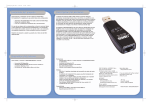
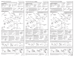
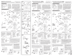
1
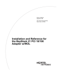
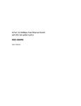
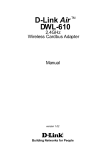
SMC2208USB/ETH
USB to 10/100 Fast Ethernet Converter
•
•
•
•
•
USB specification 1.1
IEEE 802.3 and IEEE 802.3u
Provides full-duplex to enhance throughput
Support USB suspend / Resume detection logic
Support Windows Plug & Play
Installation Guide
SMC2208USB/ETH
EZ Connect USB/ETH User Guide
?
?
?
?
?
?
?
?
?
?
?
?
?
?
?
?
?
?
?
?
?
?
?
?
?
?
?
?
?
?
?
?
?
?
?
?
?
From SMC s EZ line of low-cost workgroup LAN solutions
)X
@1
3@
S5
.Y
6 Hughes
Irvine, CA 92618
Phone: (949) 707-240
Pub. # 01-111281-006
Copyright
Information furnished by SMC Networks, Inc. (SMC) is believed to be
accurate and reliable. However, no responsibility is assumed by SMC for its
use, nor for any infringements of patents or other rights of third parties
which may result from its use. No license is granted by implication or
otherwise under any patent or patent rights of SMC. SMC reserves the right
to change specifications at any time without notice.
Copyright (c) 2001 by
SMC Networks, Inc.
6 Hughes, Irvine, CA.
All rights reserved. Printed in Taiwan
Trademarks:
SMC is a registered trademark; and EZ Connect is a trademark of SMC
Networks, Inc. Other product and company names are trademarks or
registered trademarks of their respective holders.
LIMITED WARRANTY
W.e?W.?hg
?W.YeW.Y?hg
?7U?e7U
?@1?e@1
?@@?e@@
@@e?@@?hg
3@e?3@?hg
S5e?S5?hg
?W.YeW.Y?hg
?.Y?e.Y
Limited Warranty Statement: SMC Networks, Inc. ( SMC ) warrants
its products to be free from defects in workmanship and materials, under
normal use and service, for the applicable warranty term. All SMC products
carry a standard 90-day limited warranty from the date of purchase from SMC
or its Authorized Reseller. SMC may, at its own discretion, repair or replace
any product not operating as warranted with a similar or functionally
equivalent product, during the applicable warranty term. SMC will endeavor
to repair or replace any product returned under warranty within 30 days of
receipt of the product.
The standard limited warranty can be upgraded to a Limited Lifetime*
warranty by registering new products within 30 days of purchase from SMC
or its Authorized Reseller. Registration can be accomplished via the enclosed
product registration card or online via the SMC web site. Failure to register
will not affect the standard limited warranty. The Limited Lifetime warranty
covers a product during the Life of that Product, which is defined as the
period of time during which the product is an Active SMC product. A
product is considered to be Active while it is listed on the current SMC
price list. As new technologies emerge, older technologies become obsolete
and SMC will, at its discretion, replace an older product in its product line
with one that incorporates these newer technologies. At that point, the
obsolete product is discontinued and is no longer an Active SMC product.
A list of discontinued products with their respective dates of discontinuance
can be found at http://www.smc.com/smc/pages_html/support.html.
All products that are replaced become the property of SMC.
Replacement products may be either new or reconditioned. Any replaced or
repaired product carries either a 30-day limited warranty or the remainder of
the initial warranty, whichever is longer. SMC is not responsible for any
custom software or firmware, configuration information, or memory data of
Customer contained in, stored on, or integrated with any products returned
to SMC pursuant to any warranty. Products returned to SMC should have any
customer-installed accessory or add-on components, such as expansion
modules, removed prior to returning the product for replacement. SMC is not
responsible for these items if they are returned with the product.
Customers must contact SMC for a Return Material Authorization
number prior to returning any product to SMC. Proof of purchase may be
required. Any product returned to SMC without a valid Return Material
Authorization (RMA) number clearly marked on the outside of the package
will be returned to customer at customer s expense. For warranty claims
within North America, please call our toll-free customer support number at
(800) 762-4968. Customers are responsible for all shipping charges from their
facility to SMC. SMC is responsible for return shipping charges from SMC to
customer.
W.e?W.?hg
?W.YeW.Y?hg
?7U?e7U
?@1?e@1
?@@?e@@
W.e?W.?hg
?W.YeW.Y?hg
?7U?e7U
?@1?e@1
?@@?e@@
@@e?@@?hg
3@e?3@?hg
S5e?S5?hg
?W.YeW.Y?hg
?.Y?e.Y
@@e?@@?hg
3@e?3@?hg
S5e?S5?hg
?W.YeW.Y?hg
?.Y?e.Y
W.e?W.?hg
?W.YeW.Y?hg
?7U?e7U
?@1?e@1
?@@?e@@
W-X?
*@1?
V'@?
?S5?
?.Y?
@@e?@@?hg
3@e?3@?hg
S5e?S5?hg
?W.YeW.Y?hg
?.Y?e.Y
WARRANTIES EXCLUSIVE: IF AN SMC PRODUCT DOES NOT OPERATE
AS WARRANTED ABOVE, CUSTOMER S SOLE REMEDY SHALL BE REPAIR OR
REPLACEMENT OF THE PRODUCT IN QUESTION, AT SMC S OPTION. THE
FOREGOING WARRANTIES AND REMEDIES ARE EXCLUSIVE AND ARE IN
LIEU
OF ALL OTHER WARRANTIES OR CONDITIONS, EXPRESS OR
IMPLIED, EITHER IN FACT OR BY OPERATION OF LAW, STATUTORY OR
OTHERWISE, INCLUDING WARRANTIES OR CONDITIONS OF
MERCHANTABILITY AND FITNESS FOR A PARTICULAR PURPOSE. SMC
NEITHER ASSUMES NOR AUTHORIZES ANY OTHER PERSON TO ASSUME
FOR IT ANY OTHER LIABILITY IN CONNECTION WITH THE SALE,
INSTALLATION, MAINTENANCE OR USE OF ITS PRODUCTS. SMC SHALL NOT
BE LIABLE UNDER THIS WARRANTY IF ITS TESTING AND EXAMINATION
DISCLOSE THE ALLEGED DEFECT IN THE PRODUCT DOES NOT EXIST OR
WAS CAUSED BY CUSTOMER S OR ANY THIRD PERSON S MISUSE,
NEGLECT,
IMPROPER INSTALLATION OR TESTING, UNAUTHORIZED ATTEMPTS
TO REPAIR, OR ANY OTHER CAUSE BEYOND THE RANGE OF THE INTENDED
USE, OR BY ACCIDENT, FIRE, LIGHTNING, OR OTHER HAZARD.
LIMITATION OF LIABILITY: IN NO EVENT, WHETHER BASED IN
CONTRACT OR TORT (INCLUDING NEGLIGENCE), SHALL SMC BE LIABLE
FOR INCIDENTAL, CONSEQUENTIAL, INDIRECT, SPECIAL, OR PUNITIVE
DAMAGES OF ANY KIND, OR FOR LOSS OF REVENUE, LOSS OF BUSINESS,
OR OTHER FINANCIAL LOSS ARISING OUT OF OR IN CONNECTION WITH
THE SALE, INSTALLATION, MAINTENANCE, USE, PERFORMANCE, FAILURE,
OR INTERRUPTION OF ITS PRODUCTS, EVEN IF SMC OR ITS AUTHORIZED
RESELLER HAS BEEN ADVISED OF THE POSSIBILITY OF SUCH DAMAGES.
SOME STATES DO NOT ALLOW THE EXCLUSION OF IMPLIED
WARRANTIES OR THE LIMITATION OF INCIDENTAL OR CONSEQUENTIAL
DAMAGES FOR CONSUMER PRODUCTS, SO THE ABOVE LIMITATIONS AND
EXCLUSIONS MAY NOT APPLY TO YOU. THIS WARRANTY GIVES YOU
SPECIFIC LEGAL RIGHTS, WHICH MAY VARY FROM STATE TO STATE.
NOTHING IN THIS WARRANTY SHALL BE TAKEN TO AFFECT YOUR
STATUTORY RIGHTS.
W-X?
*@1?
V'@?
?S5?
?.Y?
W-X?
*@1?
V'@?
?S5?
?.Y?
W-X?
*@1?
V'@?
?S5?
?.Y?
*
W-X?
*@1?
V'@?
?S5?
?.Y?
SMC will provide warranty service for one year following discontinuance
from the active SMC price list. Under the limited lifetime warranty,
internal and external power supplies, fans, and cables are covered by a
standard one-year warranty from date of purchase.
SMC Networks, Inc.
6 Hughes
Irvine, CA 92618
The information in this manual is subject to change without notice. All the
brand names are registered trademarks of their respective companies.
COMPLIANCES
FCC Class A
This equipment has been tested and found to comply with the limits
for a Class A digital device pursuant to Part 15 of FCC Rules. These limits are
designed to provide reasonable protection against harmful interference when
the equipment is operated in commercial environment.
This equipment generates, uses, and can radiate radio frequency
energy, and if not installed and used in accordance with the instruction
manual may cause harmful interference to radio communications. Its
operation in a residential area is likely to cause harmful interference in which
case the user will be required to correct the interference at his own expense.
EC Conformance Declaration - Class A
SMC contact for these products in Europe is:
SMC Networks Europe,
Edificio Conata II,
Calle Fructuos Gelabert 6-8, 2o, 4a,
08970 - Sant Joan Despi,
Barcelona, Spain.
This information technology equipment complies with the requirements of the
Low Voltage Directive 73/23/EEC and the EMC Directive 89/336/EEC, and
carries the CE Mark accordingly. It conforms to the following specifications:
EMC: EN55024 (1998)/CISPR-22 (1995) Class A
IEC 61000-4-2 (1995)
4 kV CD, 8 kV AD
IEC 61000-4-3 (1995)
3 V/m
IEC 61000-4-4 (1995)
1.0 kV - (power line)
0.5 kV - (signal line)
IEC 61000-4-5 (1995)
2 kV - (line to line)
1 kV - (line to ground)
IEC 61000-4-6 (1995)
3 Vrms
IEC 61000-4-11 (1995)
Voltage dip
>95% - 10 ms
30% - 500 ms
60% - 100 ms
Voltage interruption >95% - 5000 ms
Industry Canada - Class A
This digital apparatus does not exceed the Class A limits for radio
noise emissions from digital apparatus as set out in the interference-causing
equipment standard entitled "Digital Apparatus", ICES-003 of Industry
Canada.
Cet appareil numerique respecte les limites de bruits radioelectriques
applicables aux
appareils numeriques de Classe A prescrites dans la norme sur le material
brouilleur:
"Appareils Numeriques", NMB-003 edictee par l Industrie.
W-X?
*@1?
V'@?
?S5?
?.Y?
Safety Compliance
CSA/NRTL (C22.2.950, UL 1950)
EN 60950, (IEC 950)
Wichtige Sicherheitshinweise (Germany)
1. Bitte lesen Sie diese Hinweise sorgfaltig durch.
2. Heben Sie diese Anleitung fur den spateren Gebrauch auf.
3. Vor jedem Reinigen ist das Gerat vom Stromnetz zu trennen. Verwenden
Sie keine Flussigoder Aerosolreiniger. Am besten eignet sich ein
angefeuchtetes Tuch zur Reinigung.
4. Die Netzanschlu ssteckdose soll nahe dem Gerat angebracht und leicht
zuganglich sein.
5. Das Gerat ist vor Feuchtigkeit zu schutzen.
6. Bei der Aufstellung des Gerates ist auf sicheren Stand zu achten. Ein
Kippen oder Fallen konnte Beschadigungen hervorrufen.
7. Die Beluftungsoffnungen dienen der Luftzirkulation, die das Gerat vor
Uberhitzung schutzt. Sorgen Sie dafur, das diese Offnungen nicht
abgedeckt werden.
8. Beachten Sie beim Anschlus an das Stromnetz die Anschluswerte.
9. Verlegen Sie die Netzanschlusleitung so, das niemand daruber fallen
kann. Es sollte auch nichts auf der Leitung abgestellt werden.
10. Alle Hinweise und Warnungen, die sich am Gerat befinden, sind zu
beachten.
11. Wird das Gerat uber einen langeren Zeitraum nicht benutzt, sollten Sie es
vom Stromnetz trennen. Somit wird im Falle einer Uberspannung eine
Beschadigung vermieden.
12. Durch die Luftungsoffnungen durfen niemals Gegenstande oder
Flussigkeiten in das Gerat gelangen. Dies konnte einen Brand bzw.
elektrischen Schlag auslosen.
13. Offnen sie niemals das Gerat. Das Gerat darf aus Grunden der
elektrischen Sicherheit nur von authorisiertem Servicepersonal geoffnet
werden.
14. Wenn folgende Situationen auftreten ist das Gerat vom Stromnetz zu
trennen und von einer qualifizierten Servicestelle zu uberprufen:
a. Netzkabel oder Netzstecker sind beschadigt.
b. Flussigkeit ist in das Gerat eingedrungen.
c. Das Gerat war Feuchtigkeit ausgesetzt.
d. Wenn das Gerat nicht der Bedienungsanleitung entsprechend
funktioniert oder Sie mit Hilfe dieser Anleitung keine Verbesserung
erzielen.
e. Das Gerat ist gefallen und/oder das Gehause ist beschadigt.
f. Wenn das Gerat deutliche Anzeichen eines Defektes aufweist.
15. Zum Netzanschlus dieses Gerates ist eine geprufte Leitung zu
verwenden. Fur einen Nennstrom bis 6 A und einem Gerategewicht
groser 3 kg ist eine Leitung nicht leichter als H05VV-F, 3G, 0.75 mm2
einzusetzen.
Der arbeitsplatzbezogene Schalldruckpegel nach DIN 45 635 Teil 1000 betragt
70 dB(A) oder weniger.
TABLE OF CONTENTS
Chapter 1 - Introduction
Chapter 2 - Getting Started
* Setup for Windows 98
* Setup for Windows 2000
* Setup for Windows ME
Chapter 3 - Application
Chapter 4 - Troubleshooting
Chapter 5 - Specifications
7
Chapter 1 - Introduction
ABOUT THE EZ CONNECT
USB/ETHERNET CONVERTER
SMC's family of USB products offers a convenient and cost-effective
means of bringing straightforward peripheral connectivity to the desktop
based on the Universal Serial Bus (USB). These products feature true plugoutside the box
and mark a
and-play connection of PC peripherals
significant advance in desktop cable management. Using the EZ Connect(tm)
USB/Ethernet Converter you can simplify PC connections in the home, office
or on the road.
The Universal Serial Bus is designed to replace the current serial,
parallel, and other port types used on a PC with a single universal interface.
Many different types of devices can be attached to a single PC USB interface
by using a cascade of USB hubs (such as SMC s EZ Hub USB).
upstream
USB uses a unique cable and connector system. The
side of the USB cable ( A side) connects to a USB hub or PC; and the
downstream side ( B side) connects to USB devices or to another hub
s A side. The USB/Ethernet Converter has a B side connector on one side
and an RJ-45 Ethernet connector on the other side. This USB Ethernet
converter allows you to connect to a 10BASE-T or 100BASE-TX LAN using
your computer s USB interface.
W.e?W.?hg
?W.YeW.Y?hg
?7U?e7U
?@1?e@1
?@@?e@@
@@e?@@?hg
3@e?3@?hg
S5e?S5?hg
?W.YeW.Y?hg
?.Y?e.Y
W-X?
*@1?
V'@?
?S5?
?.Y?
W.e?W.?hg
?W.YeW.Y?hg
?7U?e7U
?@1?e@1
?@@?e@@
W.e?W.?hg
?W.YeW.Y?hg
?7U?e7U
?@1?e@1
?@@?e@@
W.e?W.?hg
?W.YeW.Y?hg
?7U?e7U
?@1?e@1
?@@?e@@
@@e?@@?hg
3@e?3@?hg
S5e?S5?hg
?W.YeW.Y?hg
?.Y?e.Y
W.e?W.?hg
?W.YeW.Y?hg
?7U?e7U
?@1?e@1
?@@?e@@
@@e?@@?hg
3@e?3@?hg
S5e?S5?hg
?W.YeW.Y?hg
?.Y?e.Y
W.e?W.?hg
?W.YeW.Y?hg
?7U?e7U
?@1?e@1
?@@?e@@
W-X?
*@1?
V'@?
?S5?
?.Y?
SMC2208USB/ETH
8
@@e?@@?hg
3@e?3@?hg
S5e?S5?hg
?W.YeW.Y?hg
?.Y?e.Y
@@e?@@?hg
3@e?3@?hg
S5e?S5?hg
?W.YeW.Y?hg
?.Y?e.Y
@@e?@@?hg
3@e?3@?hg
S5e?S5?hg
?W.YeW.Y?hg
?.Y?e.Y
W-X?
*@1?
V'@?
?S5?
?.Y?
Features and Benefits
*
*
*
*
*
*
*
*
USB specification 1.0 & 1.1 for standards-based compliance to ensure
compatibility
IEEE 802.3 for 10Base-T and IEEE 802.3u for 100Base-TX compliant
Automatically negotiates 10 or 100 Mbps connection rate, depending on
the speed of the network for maximum data transfer
Provides full-duplex to enhance throughput of data with no latency
Support USB suspend / Resume detection logic to ensure consistent
stream of information
Support Windows Plug & Play, Hot swap
3.3V low power consumption
LEDs diagnostics and monitoring indicators
Network interface
RJ-45 to connect with 10BASE-T or 100 BASE-TX Hub
Driver support
NDIS 5 Miniport Driver for Microsoft Windows 98/ME, and Windows 2000.
Physical characteristics
1. Temperature: 0 ~ 70degree Celsius
2. Humidity: 10% to 90%
3. Distance: 100 meters Hub to Node
9
Chapter 2 - Getting Started
After unpacking the EZ Connect(tm) USB/Ethernet Converter, check
the contents of the box to be sure you have received the following
components:
Equipment Checklist
*
*
*
*
USB 10/100 Ethernet Adapter
Driver Diskette
This Installation Guide
Warranty Registration Card
Power Requirements
USB devices can be either self-powered or bus-powered. A device
which has no power connector is bus-powered, and derives its operating
power from the USB connection directly. The EZ Connect(tm) USB/Ethernet
Converter is bus-powered - all you need to do is plug it into a PC or selfpowered USB hub.
System Requirements
To use
*
*
*
the EZ Connect(tm) USB/Ethernet Converter you must have:
A host PC that supports the Universal Serial Bus
16 MB of RAM
Windows 98 or sooner
You also need to provide a standard twisted-pair Ethernet cable to
connect to a local network 10BASE-T/100BASE-TX hub or switch.
You will be installing the USB 10/100 Ethernet adapter in your
computer.
In order to use this device, you must have a copy of Microsoft
Windows 98/ME (or Windows 2000) operating system installed on your PC.
Some versions of Windows 95 version B (OSR2) support USB, but the device
drivers included in this package are designed specifically for Windows 98 and
Windows 2000
10
Installing the USB 10/100 Ethernet Adapter
You will need to connect your new converter to the USB port of your
Desktop or Laptop PC (shown below with a laptop).
LED Display
LED
10 Mbps
Condition
Green
Status
This LED is used to indicate the Ethernet
connected with 10
connection: Green means
Ethernet network
W.e?W.?hg
?W.YeW.Y?hg
?7U?e7U
?@1?e@1
?@@?e@@
@@e?@@?hg
3@e?3@?hg
S5e?S5?hg
?W.YeW.Y?hg
?.Y?e.Y
100 Mbps
Green
This LED is used to indicate the Ethernet speed:
connected with 100Base-TX
Green means
Ethernet network .
W.e?W.?hg
?W.YeW.Y?hg
?7U?e7U
?@1?e@1
?@@?e@@
@@e?@@?hg
3@e?3@?hg
S5e?S5?hg
?W.YeW.Y?hg
?.Y?e.Y
ACT
Green
This Green LED is used to indicate the network
activity, and will flash on and off intermittently
when the PC is transmitting or receiving packets
from the network
11
Installation - Windows 98
1.
2.
Make sure your PC is powered on and that you are in the Windows 98
operating system.
Insert the USB cable (the A-type connector) into the USB port on your
PC. The system will display the Add New Hardware Wizard dialog
box. Insert the USB 10/100 LAN driver diskette into floppy driver and
then press Next button.
W.e?W.?hg
?W.YeW.Y?hg
?7U?e7U
?@1?e@1
?@@?e@@
W.e?W.?hg
?W.YeW.Y?hg
?7U?e7U
?@1?e@1
?@@?e@@
W.e?W.?hg
?W.YeW.Y?hg
?7U?e7U
?@1?e@1
?@@?e@@
3.
Select
press
W.e?W.?hg
?W.YeW.Y?hg
?7U?e7U
?@1?e@1
?@@?e@@
@@e?@@?hg
3@e?3@?hg
S5e?S5?hg
?W.YeW.Y?hg
?.Y?e.Y
@@e?@@?hg
3@e?3@?hg
S5e?S5?hg
?W.YeW.Y?hg
?.Y?e.Y
@@e?@@?hg
3@e?3@?hg
S5e?S5?hg
?W.YeW.Y?hg
?.Y?e.Y
@@e?@@?hg
3@e?3@?hg
S5e?S5?hg
?W.YeW.Y?hg
?.Y?e.Y
Search for the Best Driver for your device (Recommended) ,
Next button.
W.e?W.?hg
?W.YeW.Y?hg
?7U?e7U
?@1?e@1
?@@?e@@
12
@@e?@@?hg
3@e?3@?hg
S5e?S5?hg
?W.YeW.Y?hg
?.Y?e.Y
4.
W.e?W.?hg
?W.YeW.Y?hg
?7U?e7U
?@1?e@1
?@@?e@@
@@e?@@?hg
3@e?3@?hg
S5e?S5?hg
?W.YeW.Y?hg
?.Y?e.Y
W.e?W.?hg
?W.YeW.Y?hg
?7U?e7U
?@1?e@1
?@@?e@@
W.e?W.?hg
?W.YeW.Y?hg
?7U?e7U
?@1?e@1
?@@?e@@
5.
@@e?@@?hg
3@e?3@?hg
S5e?S5?hg
?W.YeW.Y?hg
?.Y?e.Y
Select Floppy disk drives (or select Specify a location and type
A:\ in the location), where the device information file (.INF file) and the
driver USB100R.SYS can be found. Press Next button.
@@e?@@?hg
3@e?3@?hg
S5e?S5?hg
?W.YeW.Y?hg
?.Y?e.Y
After Windows finds the driver, the following prompt will appear:
10/100 Ethernet Adapter , press Next button.
W.e?W.?hg
?W.YeW.Y?hg
?7U?e7U
?@1?e@1
?@@?e@@
W.e?W.?hg
?W.YeW.Y?hg
?7U?e7U
?@1?e@1
?@@?e@@
@@e?@@?hg
3@e?3@?hg
S5e?S5?hg
?W.YeW.Y?hg
?.Y?e.Y
13
USB
W.e?W.?hg
?W.YeW.Y?hg
?7U?e7U
?@1?e@1
?@@?e@@
6.
After the driver is found, Windows will begin to copy all the necessary
files to install network function. If Windows tries to copy
USB100R.SYS file and displays the following dialog box, just input
A:\ to specify the location of this file.
W.e?W.?hg
?W.YeW.Y?hg
?7U?e7U
?@1?e@1
?@@?e@@
W.e?W.?hg
?W.YeW.Y?hg
?7U?e7U
?@1?e@1
?@@?e@@
7.
@@e?@@?hg
3@e?3@?hg
S5e?S5?hg
?W.YeW.Y?hg
?.Y?e.Y
@@e?@@?hg
3@e?3@?hg
S5e?S5?hg
?W.YeW.Y?hg
?.Y?e.Y
Windows may request you to
Insert Windows 98 CD-ROM into the
driver selected, and click OK . Follow the instruction and input CD-ROM
or disks, as needed, direct Windows to the proper location, and then click
OK button.
USB 10/100 Ethernet
When Windows finishes the installation, the
message box will be prompted, then click the
Finish
Adapter
button.
W.e?W.?hg
?W.YeW.Y?hg
?7U?e7U
?@1?e@1
?@@?e@@
@@e?@@?hg
3@e?3@?hg
S5e?S5?hg
?W.YeW.Y?hg
?.Y?e.Y
W.e?W.?hg
?W.YeW.Y?hg
?7U?e7U
?@1?e@1
?@@?e@@
8.
@@e?@@?hg
3@e?3@?hg
S5e?S5?hg
?W.YeW.Y?hg
?.Y?e.Y
W.e?W.?hg
?W.YeW.Y?hg
?7U?e7U
?@1?e@1
?@@?e@@
W.e?W.?hg
?W.YeW.Y?hg
?7U?e7U
?@1?e@1
?@@?e@@
9.
W.e?W.?hg
?W.YeW.Y?hg
?7U?e7U
?@1?e@1
?@@?e@@
@@e?@@?hg
3@e?3@?hg
S5e?S5?hg
?W.YeW.Y?hg
?.Y?e.Y
Your System will ask you Do you want to restart your computer now .
Click Yes to restart your computer.
W.e?W.?hg
?W.YeW.Y?hg
?7U?e7U
?@1?e@1
?@@?e@@
W.e?W.?hg
?W.YeW.Y?hg
?7U?e7U
?@1?e@1
?@@?e@@
@@e?@@?hg
3@e?3@?hg
S5e?S5?hg
?W.YeW.Y?hg
?.Y?e.Y
10. After the computer has restarted, the network function will be ready.
14
@@e?@@?hg
3@e?3@?hg
S5e?S5?hg
?W.YeW.Y?hg
?.Y?e.Y
Installation - Windows 2000
1.
2.
Make sure your PC is powered on and that you are in the Windows 2000
operating system.
Insert the USB cable (the A-type connector) into the USB port on your
PC. The system will display the Found New Hardware Wizard dialog
USB 10/100 Ethernet Adapter
driver diskette into
box. Insert the
floppy drive and then press Next button.
W.e?W.?hg
?W.YeW.Y?hg
?7U?e7U
?@1?e@1
?@@?e@@
W.e?W.?hg
?W.YeW.Y?hg
?7U?e7U
?@1?e@1
?@@?e@@
@@e?@@?hg
3@e?3@?hg
S5e?S5?hg
?W.YeW.Y?hg
?.Y?e.Y
@@e?@@?hg
3@e?3@?hg
S5e?S5?hg
?W.YeW.Y?hg
?.Y?e.Y
W.e?W.?hg
?W.YeW.Y?hg
?7U?e7U
?@1?e@1
?@@?e@@
@@e?@@?hg
3@e?3@?hg
S5e?S5?hg
?W.YeW.Y?hg
?.Y?e.Y
3. Select Search for a suitable driver for my device (Recommended)
then press the Next button
W.e?W.?hg
?W.YeW.Y?hg
?7U?e7U
?@1?e@1
?@@?e@@
W.e?W.?hg
?W.YeW.Y?hg
?7U?e7U
?@1?e@1
?@@?e@@
@@e?@@?hg
3@e?3@?hg
S5e?S5?hg
?W.YeW.Y?hg
?.Y?e.Y
15
,
@@e?@@?hg
3@e?3@?hg
S5e?S5?hg
?W.YeW.Y?hg
?.Y?e.Y
4.
Select Floppy disk drives (or select Specify a location and type
A:\ in the location), where the device information file (.INF file) and
the driver USB100.SYS can be found.
W.e?W.?hg
?W.YeW.Y?hg
?7U?e7U
?@1?e@1
?@@?e@@
W.e?W.?hg
?W.YeW.Y?hg
?7U?e7U
?@1?e@1
?@@?e@@
5.
@@e?@@?hg
3@e?3@?hg
S5e?S5?hg
?W.YeW.Y?hg
?.Y?e.Y
W.e?W.?hg
?W.YeW.Y?hg
?7U?e7U
?@1?e@1
?@@?e@@
@@e?@@?hg
3@e?3@?hg
S5e?S5?hg
?W.YeW.Y?hg
?.Y?e.Y
@@e?@@?hg
3@e?3@?hg
S5e?S5?hg
?W.YeW.Y?hg
?.Y?e.Y
W.e?W.?hg
?W.YeW.Y?hg
?7U?e7U
?@1?e@1
?@@?e@@
After Windows finds the driver, the following prompt will appear: USB
. Press
Next
button, the driver then
10/100 Ethernet Adapter
installs itself.
W.e?W.?hg
?W.YeW.Y?hg
?7U?e7U
?@1?e@1
?@@?e@@
16
W.e?W.?hg
?W.YeW.Y?hg
?7U?e7U
?@1?e@1
?@@?e@@
@@e?@@?hg
3@e?3@?hg
S5e?S5?hg
?W.YeW.Y?hg
?.Y?e.Y
6.
When Windows finishes the installation, the
USB 10/100 Ethernet
message box will be prompted, then click Finish button.
Adapter
W.e?W.?hg
?W.YeW.Y?hg
?7U?e7U
?@1?e@1
?@@?e@@
W.e?W.?hg
?W.YeW.Y?hg
?7U?e7U
?@1?e@1
?@@?e@@
7.
W.e?W.?hg
?W.YeW.Y?hg
?7U?e7U
?@1?e@1
?@@?e@@
@@e?@@?hg
3@e?3@?hg
S5e?S5?hg
?W.YeW.Y?hg
?.Y?e.Y
Please restart your computer at this point. Once your computer has
restarted, network functionality will be ready.
17
Installation - Windows ME
1.
2.
Make sure your PC is powered on and that you are at the Windows ME
operating system.
Insert the USB cable (the A-type connector) into the USB port on your
PC, Windows ME will recognize the device. It will show found New
hardware Wizard , select Automatic search for a better driver and
insert the driver diskette or CD and click Next .
W.e?W.?hg
?W.YeW.Y?hg
?7U?e7U
?@1?e@1
?@@?e@@
@@e?@@?hg
3@e?3@?hg
S5e?S5?hg
?W.YeW.Y?hg
?.Y?e.Y
W.e?W.?hg
?W.YeW.Y?hg
?7U?e7U
?@1?e@1
?@@?e@@
@@e?@@?hg
3@e?3@?hg
S5e?S5?hg
?W.YeW.Y?hg
?.Y?e.Y
W.e?W.?hg
?W.YeW.Y?hg
?7U?e7U
?@1?e@1
?@@?e@@
3.
4.
5.
Windows ME will search and recognize the driver of the Device.
Windows will automatically copy the driver files and related files into the
system.
After copying the driver files, the device installation will be complete,
click Finish .
W.e?W.?hg
?W.YeW.Y?hg
?7U?e7U
?@1?e@1
?@@?e@@
6.
@@e?@@?hg
3@e?3@?hg
S5e?S5?hg
?W.YeW.Y?hg
?.Y?e.Y
@@e?@@?hg
3@e?3@?hg
S5e?S5?hg
?W.YeW.Y?hg
?.Y?e.Y
Please restart your computer at this point. Once the computer has
restarted, network functionality will be ready.
18
Chapter 3 - Application
Network Connection
To connect the USB/Ethernet Converter to the local network, follow these
steps:
1. Prepare a straight-through twisted-pair cable, maximum length 100
meters (328 feet). Use Category 3, 4 or 5 cable for connection to 10
Mbps Ethernet, or Category 5 cable for connection to 100 Mbps Fast
Ethernet.
2. Connect one end of the cable to the RJ-45 port on the USB/ Ethernet
Converter, and the other end to any available station port on a network
hub or switch. When inserting an RJ-45 plug, be sure the tab on the plug
clicks into position to ensure that it is properly seated.
3. Check that the USB/Ethernet Converter has a valid connection by
observing the Link/Act LED. If the indicator fails to light when you
connect to a network hub or switch, see Troubleshooting on page 8.
W.e?W.?hg
?W.YeW.Y?hg
?7U?e7U
?@1?e@1
?@@?e@@
@@e?@@?hg
3@e?3@?hg
S5e?S5?hg
?W.YeW.Y?hg
?.Y?e.Y
System Network Settings
When installation is complete and you have rebooted your system, the
USB/Ethernet Converter will appear to the system as a normal Ethernet
network adapter.
To enable network access on your system, click on the Network
icon in the
Windows Control Panel.
Provide a name to identify your
computer on the network, and assign it to a workgroup or domain if
necessary. Add any additional network services or protocols you require.
If you need to access the Internet, be sure you configure the TCP/IP
protocol by specifying a DHCP server, or manually entering a valid IP address,
subnet mask, and default gateway. Also be sure to specify a domain name
server which can translate web site names (URLs) to IP addresses. Then
reboot your computer to enable your network settings.
W.e?W.?hg
?W.YeW.Y?hg
?7U?e7U
?@1?e@1
?@@?e@@
W.e?W.?hg
?W.YeW.Y?hg
?7U?e7U
?@1?e@1
?@@?e@@
@@e?@@?hg
3@e?3@?hg
S5e?S5?hg
?W.YeW.Y?hg
?.Y?e.Y
19
@@e?@@?hg
3@e?3@?hg
S5e?S5?hg
?W.YeW.Y?hg
?.Y?e.Y
USB Application Diagram
Use your new USB to Ethernet Converter to
connect a PC to your Ethernet LAN for easy
networking
Connection Path:
PC to USB to Ethernet to Hub/Switch to Broadband Router to Cable Modem
20
Chapter 4 - Troubleshooting
Symptom
You cannot connect to the network.
Probable Causes
• You did not install the software driver and USB/Ethernet Converter as
indicated in this manual.
Possible Solutions
• Uninstall the driver from your operating system, power off and
disconnect any devices attached to the converter, and disconnect it from
the USB port.
• Reinstall the converter according to the installation instructions in this
manual.
Symptom
The Link/Act LED does not light
Probable Causes
There is a connection or cabling problem
Possible Solutions
• Check that the network hub or switch is powered on.
• Be sure the network cable is properly connected to both devices.
• Verify that Category 5 cable is used for 100 Mbps connections and that
Check the
the length of the cable does not exceed 100m (328 ft).
network cable and connections for defects. Replace the defective cable if
necessary.
?W2@@?
?*@@@?
?N@@@?
@@@?
21
Symptom
You cannot access a Windows Network Service.
Probable Causes
• The Windows service you are trying to access is restricted to a specific
workgroup or domain.
Possible Solutions
• Open the Network icon under the Control Panel and assign your
computer to a workgroup or domain. Then reboot your computer to
enable the new settings.
Symptom
You cannot access a Netware Service.
Probable Causes
• You have not enabled NetWare service on your computer.
• You do not have a valid user ID or password for the server you are trying
to access.
Possible Solutions
• Open the Network icon under the Control Panel and add Netware
services. Then reboot your computer to enable the new settings.
• Contact your system administrator to obtain a user ID and password for
the server you want to access.
Symptom
You cannot connect to the Internet.
Probable Causes
• You have not yet configured your computer for TCP/IP.
Possible Solutions
• If your network does not have a DHCP server (which can dynamically
assign an IP address to your computer when it connects to the network),
contact your network administrator to obtain a valid IP address. Click on
the Network icon in the Control Panel, and specify the required TCP/IP
settings. Then reboot your computer to enable the new settings.
22
SPECIFICATIONS
Model
SMC2208USB/ETH
Network Interface
USB cable with one upstream connector, USB Type A
One downstream port, RJ-45 Ethernet (10/100 Mbps)
Wiring Topology
Point-to-point connections
Access Method
USB Port: USB spec. 1.0 and 1.1
RJ-45 Port: IEEE 802.3 and 802.3u CSMA/CD
10 and 100 Mbps baseband, full and half duplex
Standards
USB Specification 1.0 and 1.1 (USB low-power device)
IEEE 802.3 Ethernet
IEEE 802.3u Fast Ethernet
System Requirements
A PC and operating system that supports the Universal Serial Bus
(Windows 98/2000/Me/XP)
Also requires device driver (included)
Size
2.5 x .5 x .5 in (at the largest point)
Weight
.25oz
23
Input Power
3.3 V, 450mA A maximum
Temperature
o
Operating: 0 to 70 C
Humidity
10 to 90% noncondensing
Compliances
FCC Class B
VCCI Class B
CE, Class B
Current Drivers
Windows ME, 98
Windows 2000, XP
24