1
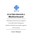
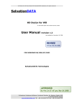
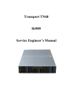
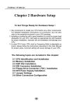
SL-KT880E-GR/RL/R
Chapter 4 AMI BIOS Setup
THE BIOS
BIOS stands for Basic Input and Output System. It was once called
ROM BIOS when it was stored in a Read-Only Memory (ROM) chip
Now manufacturers would like to store BIOS in EEPROM which means
Electrically Erasable Programmable Memory. BIOS used in this series
of mainboard is stored in EEPROM, and is the first program to run when
you turn on your computer.
BIOS performs the following functions:
1. Initializing and testing hardware in your computer (a process called
“POST”, for Power On Self Test).
2. Loading and running your operating system.
3. Helping your operating system and application programs manage
your PC hardware by means of a set of routines called BIOS RunTime Service.
This Chapter includes the following topics :
4-1 About BIOS Setup
4-2 To Run BIOS Setup
4-3 About CMOS
4-4 The POST (Power On Self Test)
4-5 To Update BIOS
4-6 BIOS Setup
Attention: The BIOS Setup is subject to constant update without further
notice to users. It is necessary for users themselves to update onboard
BIOS with the latest BIOS version provided in our web site:
http://www.soltek.com.tw
50
Chapter 4 BIOS Setup
4-1 About BIOS Setup
BIOS setup is an interactive BIOS program that you need to run when:
1. Changing the hardware of your system. (For example: installing a
new Hard Disk etc.)
2. Modifying the behavior of your computer. (For example: changing
the system time or date, or turning special features on or off etc.)
3. Enhancing your computer’s behavior. (For example: speeding up
performance by turning on shadowing or cache)
4-2 To Run BIOS Setup
First access BIOS setup menu by pressing < DEL > key after “POST” is
complete ( before OS is loaded ). BIOS will then display the following
message:
DEL:SETUP
4-3 About CMOS
CMOS is the memory maintained by a battery. CMOS is used to store
the BIOS settings you have selected in BIOS Setup. CMOS also
maintains the internal clock. Every time you turn on your computer, the
BIOS Looks into CMOS for the settings you have selected and configures
your computer accordingly. If the battery runs out of power, the CMOS
data will be lost and POST will issue a “CMOS invalid” or “CMOS
checksum invalid” message. If this happens, you have to replace the
battery and check and configure the BIOS Setup for the new start.
4-4 The POST ( Power On Self Test )
POST is an acronym for Power On Self Test. This program will test all
things the BIOS does before the operating system is started. Each of
POST routines is assigned a POST code, a unique number which is
sent to I/O port 080h before the routine is executed.
51
SL-KT880E-GR/RL/R
4-5 To Update BIOS
• System BIOS is incorporated into a Flash memory component. Flash
BIOS allows user to upgrade BIOS without the need to replace an EPROM
component.
• The Upgrade Utility can be loaded on a floppy diskette for upgrading
saving, and verifying the system BIOS. The Update Utility can also be run
from a hard disk drive or a network drive.
• It is highly recommended that you save a copy of the original mainboard
BIOS along with a Flash EPROM Programming utility (amiflash.exe) to a
bootable floppy disk so that you can reinstall the BIOS when in need.
• Normally, to update BIOS is unnecessary if the system is working fine.
Users should only update BIOS when incompatible problems are encountered or new features have to be added to system.
• “AMIFLASH.EXE” is a Flash EPROM Programming utility that updates
the BIOS by uploading a new BIOS file to the programmable flash ROM
on the mainboard. This program only works in DOS environment, the
utility can not be executed in Windows 95/98, ME, NT, 2000 or XP
environment.
• Please follow the steps below for updating the system BIOS:
Step 1. Please visit the board maker’s website, download the zip files
of the latest BIOS and AMI flash utility “amiflash.exe” for your
mainboard. After unzipping, the BIOS file format will be *.ROM, of which
“ * ” stands for the specific BIOS file name.
Step 2. Create a bootable diskette. Then copy the BIOS file and AMI
flash utility “amiflash.exe” into the diskette.
Step 3. Insert the diskette into drive A, boot your system from the
diskette.
52
Chapter 4 BIOS Setup
Step 4. Under “ A “ prompt, type “ amiflash *.ROM “ and then press
<Enter> to run BIOS update program. (*.ROM depends on your
mainboard model and version code. Instead of typing “*”, you should
type the specific file name for your specific mainboard). For example,
you may type “amiflash MP005.rom ”.
Step 5. When the message “Flash ROM Update Completed - Pass.”
appears, please restart your system.
Step 6. You will see a message “CMOS Memory Size Wrong” during
booting the system. Press <Del> or <F1> to run CMOS setup utility,
then reload “Load Failsafe Defaults” or “Load Optimal Defaults” and
save this change.
53
SL-KT880E-GR/RL/R
4-6 BIOS SETUP --- CMOS Setup Utility
4-6.1 CMOS Setup Utility
This mainboard comes with the AMI BIOS from American Megatrends
Inc. Enter the CMOS Setup Utility Main Menu by:
1. Turn on or reboot your system. After a series of diagnostic checks,
the following message will appear:
PRESS <Del> TO RUN SETUP
2. Press the <Del> key and the main program screen will appear as
follows.
CMOS Setup Utility - Copyright (C) 1985-2002, American Megatrends, Inc.
Standard BIOS Features
Discard Changes and Exit
Advanced BIOS Features
Load Optimal Defaults
Advanced Chipset Features
Load Failsafe Defaults
PCI/PNP Resource Management
Discard Changes
Boot Configuration Setup
BIOS Security Features
Save Changes and Exit
:
: Move Enter : Select
+/- : Values F10: Save
Esc: Exit F1: General Help
F7 : Previous Values
F8 : Fail-Safe Defaults
F9: Optimize Defaults
Configure Time and Date. Display System Information ...
3. Use the arrow keys on your keyboard to select an option, and press
<Enter>. Modify the system parameters to reflect the options installed
in your system.
4. You may return to the Main Menu anytime by pressing <Esc>.
5. In the Main Menu, “Save Changes and Exit” saves your changes and
reboots the system, and “Discard Changes and Exit” ignores your
changes and exits the program.
54
Chapter 4 BIOS Setup
6. In entering the Main option of the Main Menu, please use the functions in the Function List to configure the setting:
:
: Move Enter : Select
+/- : Values F10: Save
Esc: Exit F1: General Help
F7 : Previous Values
F8 : Fail-Safe Defaults
F9: Optimized Defaults
Use [Enter], [Tab] or [Shift-Tab] to select a field.
Use [+] or [-] to choose the options.
<F1>: “General Help” provides explanations of the hot-key functions
available.
<F7>: “Previous values” allows user to discard previous values or not.
<F8>: “Fail-safe defaults” allows user to load Fail-safe Defaults or not. Save
and Exit Setup.
<F9>: “Optimized Defaults” alows user to load Optimal Defaults or not.
Attention: The BIOS Setup is subject to constant update without further
notice to users. It is necessary for users themselves to update onboard
BIOS with the latest BIOS version provided in our web site:
http://www.soltek.com.tw
55
SL-KT880E-GR/RL/R
4-6.2 Standard BIOS Features
“Standard BIOS Features” allows users to configure Time and Date.
This menu also displays system information.
Run the Standard BIOS Features as follows:
Choose “Standard BIOS Features” from the Main Menu and press
<Enter>. The following screen will appear:
CMOS Setup Utility - Copyright (C) 1985-2002, American Megatrends, Inc.
Standard BIOS Features
Help Item
System Overview
Use [Enter], [Tab] or [ShiftTab] to select a field.
AMIBIOS
Version
Build Date
ID
: 08.00.11
: 02/06/04
: 0AAAA000
Use [+] or [-] to configure
system Time.
Processor
Type
Speed
Count
: AMD Athlon(tm) XP 1800+
: 1533MHz
: 1
System Memory
Size
: 256MB
System Time
System Date
:
00 : 19 : 29
Mon 02/09/2004
: Move Enter : Select
+/- : Values F10: Save
Esc: Exit F1: General Help
F7 : Previous Values
F8 : Fail-Safe Defaults
F9: Optimized Defaults
AMIBIOS/Processor/System memory
These three items only show the respective current statuses. They cannot be changed in the
BIOS Setup.
System Time
The BIOS shows the time of the day in the format: hh:mm:ss. Choose the field with the Arrow
keys and change the time with the Page Up/Page Down +/- keys.
System Date
The BIOS shows the date of the day in the format: mm:dd:yy :day of the Week. Choose the
field with the Arrow keys and change the value with the Page Up/Page Down +/- keys.
56
Chapter 4 BIOS Setup
4-6.3 Advanced BIOS Features
Advanced BIOS Features allows user to configure HDD, Floppy, Serial
Port, Parallel Port etc....
Run the Advanced BIOS Features as follows:
Choose “Advanced BIOS Features” from the Main Menu and a screen
with a list of options will appear:
CMOS Setup Utility - Copyright (C) 1985-2002, American Megatrends, Inc.
Advanced BIOS Features
Help Item
Advanced Settings
Warning: Setting wrong values in below sections
may cause system to malfunction.
IDE Configuration
Floppy Configuration
SuperIO Configuration
Hardware Health Configuration
ACPI Configuration
Power Manager Configuration
USB Configuration
Clock Generator Configuration
CPU/Voltage Configuration
:
Press Enter
Press Enter
Press Enter
Press Enter
Press Enter
Press Enter
Press Enter
Press Enter
Press Enter
: Move Enter : Select
+/- : Values F10: Save
Esc: Exit F1: General Help
F7 : Previous Values
F8 : Fail-Safe Defaults
F9: Optimized Defaults
57
SL-KT880E-GR/RL/R
4-6.3.1 IDE Configuration
Choose “IDE Configuration” in “Advanced BIOS Features” and press
<Enter>. The following sub-screen will appear for IDE Devices
configuration:
IDE Configuration
Help Item
IDE Configuration
OnBoard PCI IDE Controller
Both
Primary IDE Master
Primary IDE Slave
Secondary IDE Master
Secondary IDE Slave
Third IDE Master
Fourth IDE Master
Hard Disk
ATAPI CDROM
Not Detected
Not Detected
Not Detected
Not Detected
OnBoard PCI IDE Controller
Allows you to enable/disable onboard PCI IDE controller.
Choices: Disabled; Primary; Secondary; Both
58
Chapter 4 BIOS Setup
4-6.3.1-1 Primary/Secondary IDE Master/Slave
Primary IDE Master
Primary IDE Slave
Secondary IDE Master
Secondary IDE Slave
Third IDE Master
Fourth IDE Master
Hard Disk
ATAPI CDROM
Not Detected
Not Detected
Not Detected
Not Detected
Press <Enter> to show the detected information of Primary/Secondary
IDE Master/slave device(s). If any IDE device is detected in any one of
the above items press <Enter> to reveal the IDE information:
Primary/(Secondary) IDE Master/(Slave)
Primary/(Secondary) IDE Master/(Slave)
Help Item
Device
: Hard Disk
Vendor
: WDC WD400BB-00DEA0
Size
: 40.0GB
LBA Mode : Supported
Block Mode : 16Sectors
PIO Mode : 4
Async DMA : MultiWord DMA-2
Ultra DMA : Ultra DMA-5
S.M.A.R.T. : Supported
Type
LBA/Large mode
Block (Multi-Sector Transfer)
PIO Mode
DMA Mode
S.M.A.R.T.
32Bit Data Transfer
Auto
Auto
Auto
Auto
200MHz
Auto
Disabled
Type
To select the types of the IDE devices:
Not Installed;
Auto: Setting type automatically
CD-ROM: ATAPI (Packet Interface) CD-ROM drive
ARMD: ATAPI Removable Media Device
LBA/Large mode
To select or disable LBA/Large mode.
Block (Multi-Sector Transfer)
To select or disable Block Mode. The data transfer from and to the device occurs one
sector or multiple sectors at a time.
PIO Mode
To select or disable PIO Mode.
Choices: Disabled; 1, 2, 3, 4
DMA Mode
To select DMA Mode.
Choices: Auto; SWDMAn; MWDMAn; UDMAn
S.M.A.R.T
Allows you to enable / disable the Self Monitoring Analysis and Reporting Technology for the
hard disk.
32Bit Data Transfer
To auto-select (default) or disable 32Bit Data Transfer.
59
SL-KT880E-GR/RL/R
4-6.3.2 Floppy Configuration
Choose “Floppy Configuration” in “Advanced BIOS Features” and press
<Enter>. The following sub-screen will appear for configuration:
Floppy Configuration
Help Item
Floppy Configuration
Floppy A
Floppy B
:
1.44 MB 3.5 in
Disabled
: Move Enter : Select
+/- : Values F10: Save
Esc: Exit F1: General Help
F7 : Previous Values
F8 : Fail-Safe Defaults
F9: Optimized Defaults
Floppy A/B
Press Enter on “Floppy A/B” will let you select this field to the type(s) of floppy disk drive(s)
installed in your system.
The choices are:
360KB 5.25 in.;
1.2MB, 5.25 in.;
720KB, 3.5 in.;
1.44MB, 3.5 in.;
2.88MB, 3.5 in.;
Disabled
60
Chapter 4 BIOS Setup
4-6.3.3 Super IO Configuration
Choose “SuperIO Configuration” in “Advanced BIOS Features” and press
<Enter>. The following sub-screen will appear for configuration:
SuperIO Configuration
Help Item
Configure ITE8705 Super IO Chipset
OnBoard Floppy Controller
Serial Port1 Address
Serial Port2 Address
Serial Port2 Mode
OnBoard CIR Port
Parallel Port Address
Parallel Port Mode
Parallel Port IRQ
Enabled
3F8/IRQ4
2F8/IRQ3
Standard
Disabled
378
Normal
IRQ7
OnBoard Floppy Controller
Allows you to enable / disable the Onboard Floppy Controller.
Choices: Enabled; Disabled
Serial Port1 Address
Allows you to set the Onboard Serial Port1 Address.
Choices: Disabled; 3F8/IRQ4; 3E8/IRQ4; 2E8/IRQ3;
Serial Port2 Address
Allows you to set the Onboard Serial Port2 Address.
Choices: Disabled; 2F8/IRQ3; 3E8/IRQ4; 2E8/IRQ3;
Serial Port 2 Mode
If Serial Port2 Address is not disabled, it allows you to set the Serial Port 2 Mode.
Choices are:
Standard;
IrDA SIR: Providing 3 items for configuration:
IR Duplex Mode:
Half Duplex; Full Duplex
IR Tx2Rx 40-Bits Delay Sel:
No 40-Bits Delay; Tx 40-Bits Delay
ASK IR: Providing 3 items for configuration:
IR Duplex Mode:
Half Duplex; Full Duplex
IR Tx2Rx 40-Bits Delay Sel:
No 40-Bits Delay; Tx 40-Bits Delay
IR Rx2Tx 40-Bits Delay Sel:
No 40-Bits Delay; Rx 40-Bits Delay
OnBoard CIR Port
Allows you to set the onboard CIR Port.
Choices: Disabled; 2E0; 3E0; 298
CIR Port IRQ
If Onboard CIR Port is not disabled, this item appears to allow you to set the onboard CIR
Port IRQ for 2E0 ,3E0 and 298
Choices for 2E0, 3E0 and 298:
IRQ3; IRQ4; IRQ10; IRQ11
61
SL-KT880E-GR/RL/R
Parallel Port Address
Allows you to configure Parallel Port Address.
Choices: Disabled; 378; 278; 3BC;
Parallel Port Mode
If Parallel Port Address is set 378/278/3BC, Parallel Port Mode appears to allow you to set
the Parallel Port Mode. The choices are:
Normal;
EPP;
EPP & ECP:
ECP Mode DMA Channel:
DMA0; DMA1; DMA3
Parallel Port IRQ: IRQ5; IRQ7
If Parallel Port Address is set 378/278/3BC, Parallel Port IRQ appears to allow you to set
the Parallel Port IRQ.
Choices:IRQ5; IRQ7
62
Chapter 4 BIOS Setup
4-6.3.4 Hardware Health Configuration
Choose “Hardware Health Configuration” in “Advanced BIOS Features” and press <Enter>. The following sub-screen will appear for
configuration:
Hardware Health Configuration
Help Item
Hardware Health Configuration
ABS II Temperature
ABS II Shut Down Temperature
CPU Temperature
System Temperature
Fan1 Speed
Fan2 Speed
Fan3 Speed
Vcore
V2.5
Vcc3
Vcc
-5V
+12Vin
-12.0V
SB5V
VBAT
:
: 43˚C/111˚F
: 85˚C/185˚F
: 34˚C/93˚F
: 32˚C/89˚F
: 3125 RPM
: 3169 RPM
: 0 RPM
: 1.500 V
: 2.480 V
: 3.258 V
: 5.094V
: -5.254V
: 12.074 V
: -12.048 V
: 5.134 V
: 3.444 V
: Move Enter : Select
+/- : Values F10: Save
Esc: Exit F1: General Help
F7 : Previous Values
F8 : Fail-Safe Defaults
F9: Optimize Defaults
ABS II Temperature
Shows current CPU internal temperature.
ABS II Shutdown Temperature
This feature allows you to set the shutdown temperature to the running CPU.
Choices: Disabled; 75 0C~100 0C in 5 0C stepping
CPU Temperature
Shows current CPU external temperature.
System temperature
Shows current system temperature.
Fan1/2/3 Speed
Displaying the current speed of CPU/Power/Chassis Fan.
VCore
Showing CPU core actual voltage value.
V2.5/Vcc3/Vcc/-5V/+12Vin/-12V/SB5V/VBAT
Showing current voltage against the V2.5/Vcc3/Vcc/-5V/+12Vin/-12V/SB5V/VBAT power
supply.
63
SL-KT880E-GR/RL/R
4-6.3.5 ACPI Configuration
Choose “ACPI Configuration” in “Advanced BIOS Features” and press
<Enter>. The following sub-screen will appear for ACPI configuration:
ACPI Configuration
Help Item
ACPI Settings
ACPI Aware O/S
Yes
General ACPI Configuration
Press Enter
General ACPI
Configuration settings
ACPI Aware O/S
Allows you to enable ACPI Aware O/S function if your O/S supports ACPI. Windows XP,
2000, 98SE all support ACPI. Choices:
Yes: If “Yes” it allows you to configure “General ACPI”.
No: If “No”, no “General ACPI” to be configured.
General ACPI Configuration:
Pressing < Enter > on General ACPI Configuration will reveal the following
item(s).
Suspend mode
This item allows you to select the Suspend mode. You can select S3(STR) for suspending to DRAM if your system supports this mode. Or you can select S1 (POS) for Power on
Suspend under ACPI mode.
Choices: S1(POS); S3(STR)(Optional); Auto
(Optional) USB Device Wakeup Function
This item allows you to enable / disable the USB device Wakeup function.
64
Chapter 4 BIOS Setup
4-6.3.6 Power Manager Configuration
Choose “Power Manager Configuration” in “Advanced BIOS Features”
and press <Enter>. The following sub-screen will appear for
configuration:
Power Management
Help Item
APM Configuration
Power Management/APM
Enabled
Power Button mode
Restore on AC Power Loss
On/Off
Last State
Standby Time Out
Suspend Time Out
Disabled
Disabled
Advanced Resume Events Controls
Resume On Ring
Resume On Lan
Resume On PME#
Resume On RTC Alarm
RTC Alarm Date
RTC Alarm Hour
RTC Alarm Minute
RTC Alarm Second
Disabled
Disabled
Disabled
Disabled
15
12
30
30
Power Management/APM
To enable/ disable the Power management
Power Button Mode
To set power Button function.
Choices: On/Off; Suspend; Standby
Restore on AC/Power Loss
To set the restore state from AC/Power Loss.
Choices: Last State; Power Off ; Power On
Standby Time Out (Minute)
To set the duration of Standby Time Out.
Choices: Disabled; 1; 2; 4; 8; 10; 20; 30; 40; 50; 60
Suspend Time Out (Minute)
To set the duration of Suspend Time Out.
Choices: Disabled; 1; 2; 4; 8; 10; 20; 30; 40; 50; 60
65
Enable or disable APM.
SL-KT880E-GR/RL/R
Advanced Resume Events Controls
Resume on Ring
Allows you to enable / disable the Resume on Ring Signal function.
An input signal on the serial Ring Indicator (RI) Line (in other words, an incoming call on the
modem) awakens the system from a soft off state.
Resume on Lan
Allows you to enable / disable the Resume on Lan function.
Resume on PME#
Allows you to enable / disable the Resume on PME# function.
Resume On RTC Alarm
Allows you to enable / disable the Resume On RTC Alarm function.
If enabled, the following items will appear for user’s configuration.
RTC Alarm Date / Hour / Minute / Second
If resume On RTC Alarm is enabled, this field allows you to set the Alarm date Hour, Minute
and second.
RTC Alarm Date (Days) : Every Day; 01 ~ 31
RTC Alarm Hour (hours): 00 ~ 23
RTC Alarm Minutes (Minutes): 00 ~ 59
RTC Alarm Second (Seconds): 00 ~ 59
4-6.3.7 USB Configuration
Choose “USB Configuration” in “Advanced BIOS Features” and press
<Enter>. The following sub-screen will appear for configuration:
USB Configuration
Help Item
USB Configuration
Enable USB host
controllers.
Module Version - 2.23.0-7.4
USB Devices Enabled :
None
USB 1.1 Ports configuration
USB 2.0 Ports Enable
Legacy USB Support
USB 2.0 Controller Mode
USB 8 Ports
Enabled
Enabled
HiSpeed
USB 1.1 Ports Configuration
Allows you to set the USB 1.1 port(s).
Choices: 8 USB Ports; Disabled
USB 2.0 Ports Enable
Allows you to enable / disable the USB 2.0 Ports.
Legacy USB Support
Allows you to enable / disable the Legacy USB support.
Choices: Enabled; Disabled; Auto
USB 2.0 Controller Mode
Allows you to configure the USB 2.0 Controller Mode.
Choices: FullSpeed(12Mbps); HiSpeed(480Mbps)
66
Chapter 4 BIOS Setup
4-6.3.8 Clock Generator Configuration
Choose “Clock Generator Configuration” in “Advanced BIOS Features”
and press <Enter>. The following sub-screen will appear for
configuration:
Clock Generator Configuration
Help Item
Configure ICS ICS94230 Clock Generator
CPU Linear Frequency
CPU Frequency Setting
Enabled
133
AGP/PCI Clock (Mhz)
66.67/33.33
Spread Spectrum
Auto PCI Clock
Disabled
Disabled
CPU Linear Frequency
Allows you to enable / disable / auto-detect the CPU Linear Frequency setting.
If enabled, the CPU Frequency Setting item will appear for user’s configuration.
CPU Frequency Setting
This item allows you to set CPU Clock.
Choices: 100MHz ~200MHz in 1MHz stepping.
(100MHz~132MHz is for 100MHz CPU; 133MHz~165MHz is for 133MHz CPU;
166MHz~200MHz is for 166MHz CPU.)
AGP/PCI Clock(Mhz)
Shows the current AGP/PCI Clock
Spread Spectrum
This function will reduce the EMI (Electromagnetic Interference) in your system. If you do
not have an EMI problem, leave this item disabled.
Auto PCI Clock
To enable/disable to automatically detect PCI clock.
67
SL-KT880E-GR/RL/R
4-6.3.9 CPU/Voltage Configuration
Choose “CPU/Voltage Configuration” in “Advanced BIOS Features” and
press <Enter>. The following sub-screen will appear for configuration:
CPU/Voltage Configuration
CPU Voltage Control
DIMM Voltage Control
VCC2.5V Voltage Control
AGP Voltage Control
Auto
2.5V
2.5V
1.5V
Help Item
CPU Configuration
CPU Ratio Selection
Default
CPU Voltage Control
Allows you to configure the CPU Voltage. Usually, to raise CPU voltage will raise the chance
of CPU overclocking and yet risk damage of CPU.
Choices: Auto; 1.100V ~1.850V in 0.025V stepping
DIMM Voltage Control
Allows you to configure the DIMM Voltage.
Choices: 2.5V; 2.6V; 2.7V; 2.8V
VCC2.5V Voltage Control
Allows you to configure the VCC2.5V Voltage.
Choices: 2.5V; 2.6V; 2.7V; 2.8V
AGP Voltage Control
Allows you to configure the AGP Voltage.
Choices: 1.5V; 1.6V; 1.7V; 1.8V
CPU Ratio Selection
Allows you to configure the CPU Ratio if the ratio is unlocked.
68
Chapter 4 BIOS Setup
4-6.4 Advanced Chipset Features
Advanced Chipset Features is used to modify the values of chipset
buffers. These buffers control the system options.
Run the Advanced Chipset Features as follows:
Choose “Advanced Chipset Features” from the Main Menu and a
list of option will appear:
CMOS Setup Utility - Copyright (C) 1985-2002, American Megatrends, Inc.
Advanced Chipset Features
Help Item
Advanced Chipset Settings
Warning: Setting wrong values in below sections
may cause system to malfunction.
NorthBridge VIA KT880 Configuration
SouthBridge VIA VT8237 Configuration
Press Enter
Press Enter
ONBOARD Gigabit Ethernet Contr(optional) Enable
:
: Move Enter : Select
+/- : Values F10: Save
Esc: Exit F1: General Help
F7 : Previous Values
F8 : Fail-Safe Defaults
F9: Optimized Defaults
69
SL-KT880E-GR/RL/R
4-6.4.1 NorthBridge Configuration
Choose “NorthBridge Configuration” in “Advanced Chipset Features”
and press <Enter>. The following sub-screen will appear for
configuration:
NorthBridge VIA KT880 Configuration
Top Performance
Disable
Help Item
******** DRAM Timing ********
DRAM Clock
By SPD
DRAM Timing
Auto By SPD
DRAM BUS Selection
Auto
Primary Graphics Adapter
VLink 8X Supported
AGP
Enabled
AGP Mode
AGP Read Synchronization
AGP Fast Write
Graphics Aperture Size
AGP 4X
Disabled
Disabled
64MB
Top Performance
Allows you to enable/disable Top Performance function.
******** DRAM Timing ********
DRAM Clock
Allows you to set the SDRAM frequency.
Choices: By SPD; 200 MHz; 266 MHz; 333 MHz; 400 MHz
DRAM Timing
Allows you to select the DRAM Timing mode.
Choices:
Auto by SPD:BIOS will access SPD (Serial Presence Detect)automatically to configure
module timing;
Turbo;
Ultra;
Manual: If DRAM Timing is set to Manual, the following 8 items will appear for user’s
configuration:
SDRAM CAS# Latency -- for SDRAM CAS#(Column Address Strode) Latency cycle:
1.5; 2.0; 2.5; 3.0
SDRAM Bank Interleave--allows you to enable / disable SDRAM Bank Interleave function:
Disabled; 2-way; 4-way
Precharge to Active(Trp)
2T; 3T; 4T; 5T
Active to Precharge(Tras):
6T; 7T; 8T; 9T;
Active to CMD(Trcd):
2T; 3T; 4T; 5T;
REF to ACT/REF to REF(Trfc):
12T; 13T; 14T; 15T;
ACT(0) to ACT(1) (Trrd):
2T; 3T;
DRAM Command Rate:
2T Command; 1T Command;
70
Chapter 4 BIOS Setup
DRAM Bus Selection
Allows you to select DRAM Bus.
Choices: Auto; Single Channel; Dual Channel
Primary Graphics Adapter
To select the Primary Graphics Adapter.
Choices: AGP; PCI
VLink 8x Supported
Allows you to enable / disable VLink 8x mode.
AGP Mode
Allows you to select the AGP Mode on board. This item supports 4X/8X AGP Mode.
AGP Read Synchronization
Allows you to enable / disable the AGP Read Synchronization.
AGP Fast Write
Allows you to enable / disable the AGP Fast Write function.
Graphics Aperture Size
Series of options are available: 4MB; 8MB; 16MB; 32MB, 64MB, 128MB, 256MB. Memory
mapped and graphics data structures can reside in a Graphics Aperture. This area is like a
linear buffer. BIOS will automatically report the starting address of this buffer to the O.S.
71
SL-KT880E-GR/RL/R
4-6.4.2 SouthBridge Configuration
Choose “SouthBridge Configuration” in “Advanced Chipset Features”
and press <Enter>. The following sub-screen will appear for
configuration:
SouthBridge Configuration
South Bridge Chipset Configuration
OnBoard SATA-IDE
OnBoard LAN (optional)
OnBoard AC’97 Audio
:
Help Item
RAID
Enabled
Enabled
: Move Enter : Select
+/- : Values F10: Save
Esc: Exit F1: General Help
F7 : Previous Values
F8 : Fail-Safe Defaults
F9: Optimized Defaults
OnBoard SATA-IDE
Allows you to configure on board SATA mode.
Choices: RAID; Disabled
OnBoard LAN
To enable / disable OnBoard LAN. (for KT880E-RL only)
OnBoard AC’ 97 Audio
To enable / disable onboard AC’ 97 Audio.
Onboard Gigabit Ethernet Contr
To enable / disable OnBoard Gigabit Ethernet Controller. (for KT880E-GR only)
72
Chapter 4 BIOS Setup
4-6.5 PCI/PNP Resource Management
PCI/PNP Resource Management allows you to modify the system’s
power saving functions.
Choose “PCI/PNP Resource Management” from the Main Menu and a
screen with a list of options will appear:
CMOS Setup Utility - Copyright (C) 1985-2002, American Megatrends, Inc.
PCI/PNP Resource Management
Help Item
Advanced PCI/PNP Settings
Warning: Setting wrong values in below sections
may cause system to malfunction.
Plug & Play O/S
PCI Latency Timer
Allocate IRQ to PCI VGA
OffBoard PCI/ISA IDE Card
PCI Slot 1/5 IRQ Preference
PCI Slot 2 IRQ Preference
PCI Slot 3 IRQ Preference
PCI Slot 4 IRQ Preference
:
No
64
Yes
Auto
Auto
Auto
Auto
Auto
: Move Enter : Select
+/- : Values F10: Save
Esc: Exit F1: General Help
F7 : Previous Values
F8 : Fail-Safe Defaults
F9: Optimized Defaults
Plug & Play O/S
To configure the PNP devices by BIOS or O/S.
Choices: No(by BIOS); Yes(by O/S)
PCI Latency Timer
To set the PCI Latency Time.
Choices: 32; 64; 96; 128; 160; 192; 224; 248;
Allocate IRQ to PCI VGA
To enable/disable to assign IRQ to PCI VGA if the VGA card
requests IRQ.
OffBoard PCI/ISA IDE Card
Some PCI IDE card may require this to be set to the PCI slot number that is holding the card.
Please leave this at default.
PCI Slot 1/2/3/4/5 IRQ Preference
To automatically or manualy assigned IRQ to the PCI Slots.
73
SL-KT880E-GR/RL/R
4-6.6 Boot Configuration Setup
Boot Configuration Setup allows you to modify the system’s boot settings
with the onboard devices.
Choose “Boot Configuration Setup” from the Main Menu and a screen
with a list of options will appear:
CMOS Setup Utility - Copyright (C) 1985-2002, American Megatrends, Inc.
Boot Configuration Setup
Help Item
Boot Settings
Boot Settings Configuration
Press Enter
Boot Device Priority
Hard Disk Drives
Removable Drives
ATAPI CDROM Drives
Press Enter
Press Enter
Press Enter
Press Enter
:
: Move Enter : Select
+/- : Values F10: Save
Esc: Exit F1: General Help
F7 : Previous Values
F8 : Fail-Safe Defaults
F9: Optimized Defaults
74
Chapter 4 BIOS Setup
4-6.6.1 Boot Settings Configuration
Choose “Boot Settings Configuration” in “Boot Configuration Setup” and
press <Enter>. The following items will appear for onfiguration:
Boot Configuration Setup
Help Item
Boot Settings Configuration
Quick Boot
AddOn ROM Display Mode
Bootup Num-Lock
PS/2 Mouse Support
Enabled
Force BIOS
On
Auto
Quick Boot
Allows you to enable / disable quick boot of your system. If
enabled, BIOS will skip certain tests while booting. This will
decrease the time needed to boot the system.
AddOn ROM Display Mode
If “Force BIOS” is chosen, the vendor’s logo screen will be
followed by the “AddOn ROM” initial screen (the screen showing the add-on card BIOS message). If “Keep Current” is
chosen, no “Add-On ROM” screen is followed.
Bootup Num-lock
To toggle between On or Off to control the state of the NumLock keys when the system
boots. If On, the numeric keypad is in numeric mode. If off, the numeric keypad is in cursor
control mode.
PS/2 Mouse Support
Allows you enable/disable PS/2 Mouse support.
75
SL-KT880E-GR/RL/R
4-6.6.2 Boot Device Priority
Choose “Boot Device Priority” in “Boot Configuration Setup” and press
<Enter>. The bootable devices installed on board will appear and are
allowed to assign the Boot Priority.
Boot Device Priority
Help Item
Boot Device Priority
1st Boot Device
2nd Boot Device
3rd Boot Device
1st FLOPPY DRIVE
PM-WDC WD400BB-00
DVD-ROM
1st/2nd/3rd Boot Device
To set (by pressing <Enter>) the already-installed devices as the 1st/2nd/3rd boot device.
Choices: Disabled; Device(s) installed
4-6.6.3 Hard Disk/Removable/ATAPI CDROM Drives
Choose “Hard Disk/Removable/CD/DVD Drives” in “Boot Configuration
Setup” and press <Enter>. The bootable devices installed on board will
appear and are allowed to assign the Boot Priority.
Boot Configuration Setup
Help Item
Boot Settings
Boot Settings Configuration
Press Enter
Boot Device Priority
Hard Disk Drives
Removable Drives
ATAPI CDROM Drives
Press Enter
Press Enter
Press Enter
Press Enter
Configure Settings
during System Boot.
Hard Disk/Removable/CD/DVD Drives
Press <Enter> to show the already-installed devices for setting Boot Priority.
76
Chapter 4 BIOS Setup
4-6.7 Boot Security Features
Boot Security Features allows you to modify the system’s boot security
settings.
Choose “Boot Security Features” from the Main Menu and a screen
with a list of options will appear:
CMOS Setup Utility - Copyright (C) 1985-2002, American Megatrends, Inc.
Boot Security Features
Security Settings
Help Item
Install or Change the
password.
Supervisor Password : Not Installed
User Password
: Not Installed
Change Supervisor Password
Change User Password
Clear User Password
Boot Sector Virus Protection
:
Press Enter
Press Enter
Press Enter
Disabled
: Move Enter : Select
+/- : Values F10: Save
Esc: Exit F1: General Help
F7 : Previous Values
F8 : Fail-Safe Defaults
F9: Optimized Defaults
4-6.7.1 Supervisor Password
To show the status of Supervisor Password. “Installed” is displayed when
supervisor password is set up. Otherwise, “Not Installed” is displayed.
4-6.7.2 User Password
To show the status of User Password. “Installed” is displayed when
supervisor password is set up. Otherwise, “Not Installed” is displayed.
77
SL-KT880E-GR/RL/R
4-6.7.3 Change Supervisor Password
This option allows you to set a new Supervisor password for the system:
1. Choose “Change Supervisor Password” in the “BIOS Security Features” and press <Enter>. Then the following message appears:
[ Enter new supervisor password ]
2. The first time you run this option, enter your password up to 6 characters and press <Enter>. (The screen does not display the entered
characters.)
3. After you enter the password, the following message appears, prompting you to confirm the password:
[ Confirm New Password ]
4. Enter the same password “exactly” the same as you have just typed
to confirm the password and press <Enter>.
5. The following message appears to confirm the new password setup.
[ Password installed ]
[OK]
6. Then press any key to continue your CMOS Setup. To save the password setup, you should press “Save Changes and Exit” and choose
“OK” to exit and save setup.
7. If you enter a new password into the box, you will be using this new
password after you have finished and saved this new setup. Instead,
if you press <Enter> before you enter any new password into the
instruction box, another message box appears, telling you that you
have disabled the Supervisor Password. That means, no password
is set for either entering BIOS Setup or system:
[ Password uninstalled ]
[OK]
User Access Level
Allows you to set four different Access Levels when Supervisor Password has been set.
Choices: Full Access; Limited; View Only; No Access
Note: “User Access Level” and “Password Check” will appear when “Supervisor Password” has been set.
78
Chapter 4 BIOS Setup
4-6.7.4 Change User Password
This option allows you to set a new User password for the system:
1. Choose “Change User Password” in the “BIOS Security Features”
and press <Enter>. Then the following message appears:
[ Enter New Password ]
2. The first time you run this option, enter your password up to 6 characters and press <Enter>. (The screen does not display the entered
characters.)
3. After you enter the password, the following message appears, prompting you to confirm the password:
[ Confirm New Password ]
4. Enter the same password “exactly” the same as you have just typed
to confirm the password and press <Enter>.
5. The following message appears to confirm the new password setup.
[ Password installed ]
[OK]
6. Then press any key to continue your CMOS Setup. To save the password setup, you should press “Save Changes and Exit” and choose
“OK” to exit and save setup.
4-6.7.5 Clear User Password
1. To remove the current user password, choose “Clear User Password”
and press <Enter>. An instruction box appears on the screen, assuring to clear User Password:
Clear User Password?
[OK]
[Cancel]
2. Then choose [OK] and press <Enter>. The User Password is successfully removed.
79
SL-KT880E-GR/RL/R
Password Check
Allows you to set BIOS to check up password with a password prompt at BIOS Setup or
whenever restarting system. This option will appear when you have set Supervisor Password or User Password.
Choices: Setup; Always
4-6.7.6 Boot Sector Virus Protection
Boot Sector Virus Protection
When enabled, you receive a warning message if a
program (specifically, a virus) attempts to write to
the boot sector or the partition table of the hard disk
drive.
You should then run an antivirus program. Keep in
mind that this feature protects only the boot sector,
not the entire hard drive.
NOTE: Many disk diagnostic programs that access the boot
sector table can trigger the virus warning message. If you
plan to run such a program, we recommend that you disable the virus warning.
4-6.8 Save Changes and Exit
Save Changes and Exit allows you to save all modifications you have
specified into the CMOS memory. Highlight this option on the Main Menu
and press <Enter>. The following message appears:
[ Saving configuration changes and exit setup? ]
[OK]
[Cancel]
Press <Enter> key to save the configuration changes and exit CMOS
Setup to restart your system.
80
Chapter 4 BIOS Setup
4-6.9 Discard Changes ( and Exit )
Discard Changes option allows you to exit (or not exit) the Setup Utility
without saving the modifications that you have specified. Highlight this
option on the Main Menu and press <Enter> and the following message
appears:
[ Discard Changes (and exit setup?)]
[OK]
[Cancel]
Follow the message and press <Enter> key to exit CMOS Setup and
restart system.
4-6.10 Load Optimal Defaults
When you press <Enter> on this item, you will get a confirmation dialog
box with a message similar to:
[ Load Optimal Defaults ?]
[OK]
[Cancel]
Press <Enter> now to load Optimal values for all the Setup options.
4-6.11 Discard Changes
Discard Changes option allows you to cancel the modifications that you
have specified in the Setup Utility. Highlight this option on the Main
Menu and press <Enter> and the following message appears:
[ Discard Changes?]
[OK]
[Cancel]
Follow the message and press <Enter> key to cancel the modifications
that you have specified.
81