1
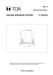
INSTRUCTION MANUAL
CIS300
2-Way Ceiling Monitor
���
��
��
��
���
��
���
����
�����
����
���������
����
����
���
����
�����
1. SAFETY INSTRUCTIONS
1.1. Read Instructions — Before connecting and using the
equipment, please read this Instruction Manual carefully and keep
it for future reference.
1.2. HEED ALL WARNINGS — Always follow the precautions
provided on this EAW Commercial product and in the instruction
manual.
1.3. Water and Humidity — Do not use this EAW Commercial
product near water; for example, in the vicinity of a bath tub or
sink, in a damp cellar, near a swimming pool, etc.
1.4. Foreign Bodies and Liquids — Be careful not to allow any
foreign bodies or liquids to get into this EAW Commercial
product.
1.5. Servicing — The user should never attempt to make any
repairs on this EAW Commercial product unless otherwise
indicated in the instruction manual. All repairs should be made by
qualified service technicians.
1.6. Installation — Do not install this EAW Commercial product in
any way that is not provided for in the instruction manual.
1.7. Respect the Safety Standards — The entire sound system
must be designed in compliance with the current standards and laws
regarding electrical systems.
1.8. Specifications — When installing and using this EAW
Commercial product, keep in mind the technical specifications
indicated in the dedicated section of the manual.
1.9. Accessories — Install and use this EAW Commercial product
only with the accessories specified by the manufacturer or
supplied with the product.
1.10. Hearing Loss — Exposure to high sound levels can cause
permanent hearing loss. The sound pressure level which leads
to hearing loss varies considerably from one person to another,
and depends on the duration of exposure. The U.S. Government’s
2. TABLE OF CONTENTS
1. SAFETY INSTRUCTIONS ...................................................2
2. TABLE OF CONTENTS ........................................................2
3. KEY FEATURES....................................................................2
4. INTRODUCTION..................................................................3
5. PRODUCT DESCRIPTION...................................................3
6. INSTALLING THE CIS300 ...................................................4
7. SPECIFICATIONS................................................................6
8. SERVICE INFORMATION ...................................................8
Part No. 0009737 Rev. A 03/04
© 2004 LOUD Technologies Inc. All Rights Reserved.
2 – CIS300
Occupational Safety and Health Administration (OSHA) has
established the maximum sound pressure levels that can be
with stood without causing damage, which are shown in the
table below. According to the OSHA regulations, any exposure
over the maximum limits indicated in the table can reduce the
hearing capacity of a person. To prevent potentially dangerous
exposure to high sound pressure levels, anyone subjected to such
levels must use suitable protection. When an EAW Commercial
product capable of producing high sound levels is being used, it
is therefore necessary to wear ear plugs or protective earphones
when the limits shown in the table are exceeded.
Consult the specifications provided in the instruction manual to
know the maximum sound pressure (SPL) the speaker is capable
of producing.
WARNING! This equipment has been designed to be installed
by qualified professionals only! There are many factors to be
considered when installing professional sound reinforcement
systems, including mechanical and electrical considerations, as
well as acoustic coverage and performance. LOUD Technologies
strongly recommends that this equipment be installed only by a
professional sound installer or contractor.
Sound level
(dBA)
Typical example
8
90
Duo in a small club
6
92
Duration per
day (hours)
4
95
3
97
2
100
1.5
102
1
105
0.5
110
0.25 or less
115
Subway train
Very loud classical music
Locomotive at 50 feet
Loudest parts at a rock concert
3. KEY FEATURES
• Proprietary waveguide design to improve
hi-frequency dispersion
• Ported design for extended low-frequency
response
• 1" soft-dome tweeter with neodymium
magnetic motor structure
• 4" low-frequency woofer
• Built-in 70/100V transformer with multiple
taps
• Transformer bypass for low-impedance
operation (16 ohms)
• True 2-way crossover
• Built-in switchable high-pass filter
• Complete assembly for quick installation
• UL/cUL/CE listed
4. INTRODUCTION
(when used with a subwoofer), and full-range low-impedance
operation (16 ohms).
The CIS300 is a complete two-way bass-reflex flush-mount
loudspeaker assembly designed for ease of installation,
extremely wide coverage, and high-fidelity full-range sound
reinforcement.
A plastic paint shield is provided that protects the
transducers so the front baffle rim and grille can be painted to
match the surrounding décor.
The CIS300 is ideal for use in business music systems and
foreground/background music applications.
Installing the CIS300 is simple. The one-piece assembly
includes the backcan, mounting tabs (clamps), front baffle rim,
high- and low-frequency drivers, and our proprietary two-way
waveguide based on the award-winning Mackie HR824 studio
monitors. Support rails are supplied that attach to the C-ring
(included) and distribute the speaker’s weight to the ceiling tile
T-channels. A template is also included for marking the correct
cutout size.
The Phoenix-style connector on the back of the assembly
provides input and loop-through connections for 70V/100V
distribution systems, or low-impedance operation. An easily
accessible rotary switch on the front panel selects the
appropriate tap (from 3.7 watts to 30 watts). A second switch
allows you to select among full-range operation, high-pass
5. PRODUCT DESCRIPTION
1. Grille
2. C-Ring
3. Support Rails
4. Mounting Tabs
5. Attachment Screws
6. Backcan
7. Terminal Cover Plate
8. Connector
9. Strain Relief
10. Seismic Safety Tab
11. Waveguide
12. Tap Selector Switch
13. Full-range/High-Pass Selector Switch
�������������
������
�����������
����
�����������������
������
����������������
������������
���
��
��
��
���
��
���
����
���
LO �
TH O
RU P
�
IN
�
�
IN
����
�����
����
���������
����
����
�����
�
�
������������
����������
�������������
�����������
�����������
�������������������������
���������������
�
LO �
TH O
RU P
����������
���������
���������
����������������
CIS300 – 3
6. INSTALLING THE CIS300
The CIS300 can be installed into suspended or drywall-based
ceilings. The speaker is secured in place with the four rotating
mounting tabs. The support rails are used with suspended
ceilings (standard 24" spacing) to transfer the weight of the
speaker to the T-channel runners.
2. Insert the C-ring (2) through the hole so the hanging
brackets on the C-ring point up. If installing in a suspended
ceiling, align the support rails (3) on either side of the hole
and hook them onto the T-channel runners in the suspended
ceiling support grid. Then slide the C-ring brackets over the
support rails as shown in the illustration below.
PLACEMENT
Support Rails
C-Ring
Bracket
There are two considerations when deciding where to place
the CIS300 speakers.
Ceiling Tile
Location: When installing the speaker in a suspended
ceiling with conventional ceiling tiles, the location of the
speaker is determined in part by the support grid of the
suspended ceiling system.
When installing the speaker in a drywall ceiling, the
location of the speaker is determined in part by the location of
the ceiling joists.
Coverage: It is important to locate the speakers in such
a way that the sound is evenly distributed over the entire
area. Keep in mind that the sound has farther to travel on the
outside edge of the coverage area for each individual speaker
than directly below the speaker, resulting in a decrease in SPL
at the outer edges of the listening plane. The CIS300 is –6 dB
at a horizontal off-axis angle of 70º from 1 kHz to 6 kHz (140º
coverage).
The speaker placement should be designed such that the
edges of the coverage pattern for each speaker are at least
touching. The more overlap that is provided (higher density
coverage), the more SPL the system is capable of providing and
the less variation in level as you move around the area. The
downside of higher density coverage, of course, is that more
speakers are required for a given area.
INSTALLATION
Note: Observe all local and national codes when installing the
CIS300.
1. Cut the hole for the speaker using the supplied cutout template.
If using a circular cutter, set the diameter
OP
LO RU
to 7.8 inches (199 mm).
TH
IN
OP IN +
LO RU –
TH –
T-Channels
3. You can install the CIS300 speakers using either conduit or
plenum-approved jacketed cable.
A. Installation with Plenum-Approved Jacketed Cable or Flexible Conduit
Note: If you can access the back of the CIS300 once it is
mounted, you may prefer to do steps A3 and A4 before doing
steps A1 and A2.
A1. Attach the speaker cable to the supplied Phoenix-type
connector (8). This is a 4-position connector, with two “+”
and two “–” terminals. Connect the speaker cable to the
“+” and “–” terminals labeled IN. If connecting another
speaker in a distributed system (in parallel), connect the
speaker cable running to the next speaker to the “+” and
“–” terminals labeled LOOP THRU.
A2. Open the terminal cover plate (7) on the back of the
CIS300. Route the speaker cable through the strain relief
bracket (9), and connect the speaker connector (8) to the
+
�
L �
TH OO
RU P �
IN
�
IN
4 – CIS300
�
�
L �
TH OO
RU P
�
4-pin terminal. Tighten the strain relief screws to secure
the speaker cable or flexible conduit. Close the terminal
cover plate (7) and tighten the locking screw (7a) firmly.
B. Installation to Conduit
B1. Remove the two screws holding the strain relief (9) onto
the rear cover and remove the strain relief assembly.
Flexible
Conduit
L �
TH OO
RU P
�
IN
�
�
IN
�
�
B2. Open the terminal cover plate (7) on the back of the
CIS300. Use a threaded conduit set-screw coupler (not
supplied: For 1/2" conduit, use Thomas&Betts Steel City
model TC221-SC or UL listed equivalent1) and insert
into the opening exposed by removing the strain relief
assembly.
L –
TH OO
RU P
IN
B3. Fasten the coupler to the cover using the nut supplied with
the coupler.
Threaded Conduit
Set-Screw Coupler
(Thomas&Betts
Steel City
TC221-SC
or equivalent)
�
�
L �
TH OO
RU P
I
�
T-Channels
N
�
�
IN
L �
TH OO
RU P
�
Ceiling Tile
1
C-Ring
Support Rails
L +
TH OO
RU P +
IN
2
–
3
4
A3. Insert the speaker into the hole all the way, so the front
baffle rim is flush against the ceiling.
�
L �
TH OO
RU P
B4. Insert the speaker into the hole
all the way, so the front baffle rim is
flush against the ceiling.
��
��
��
���
��
���
���
����
���
A4. Turn the four attachment
screws (5) clockwise until
tight to secure the mounting
tabs over the C-ring. DO NOT
OVERTIGHTEN.
����
�����
����
���������
����
����
�����
B5. Turn the four attachment screws
(5) clockwise until tight to secure
the mounting tabs over the C-ring.
DO NOT OVERTIGHTEN.
1 This method can be used with 1/2" flexible
conduit by substituting a Thomas&Betts Steel
City model XC241 flexible conduit fitting (or
UL listed equivalent).
CIS300 – 5
B6. Pull the speaker cable through the conduit coupler and
attach to the supplied Phoenix-type connector (8). This is a
4-position connector, with two “+” and two “–” terminals.
Connect the speaker cable to the “+” and “–” terminals
labeled IN. If connecting another speaker in a distributed
system (in parallel), connect the speaker cable running
to the next speaker to the “+” and “–” terminals labeled
LOOP THRU.
��
�� ��
�� �
��
�� �� �
�� �� �
�� �
�
IN
�
�������
�
IN
�
�
L �
TH OO
RU P
7. SPECIFICATIONS
System Acoustic
�
���������
B7. Close the terminal cover plate (7) and tighten the locking
screw (7a) firmly.
B8. Insert the conduit into the coupler and fasten with the setscrew.
Note: A seismic safety tab (10) is provided to secure the
loudspeaker to the building structure with wire cabling for
additional support where required by local construction
codes. We recommend using this secondary support for
additional safety.
4. Set the Tap Selector Switch (12). Make sure all the taps
in the system add up to less than the rated power of
the amplifier driving them. As a general rule, you should
provide at least 10% headroom to account for insertion
losses (i.e., wiring resistance, etc.). For example, if you
have four speakers tapped at 15 watts each, the amplifier
should be rated at least 66 watts.
���
��
��
��
���
��
���
����
�����
����
���������
����
6 – CIS300
If the speaker is being used in a low-impedance system,
use the FULL RANGE (16 OHM) position. This
bypasses the tapped transformer.
6. Install the grille (1) by pressing it into place until the front
of the grille is flush with the front baffle rim. It is important
that the grille be securely seated to avoid having it vibrate
loose.
�������
L �
TH OO
RU P
5. Set the Full-Range/High-Pass Selector Switch (13). For
normal operation, set the switch to the FULL RANGE
position. If a subwoofer is being used in the system to
reinforce the very-low frequencies, use the HIGH PASS
position to roll off the frequencies below 150 Hz. This
provides the added benefit of making more power available
for the crucial mid and high frequencies.
����
���
����
�����
Frequency Range:
90 Hz–22 kHz (–10 dB)
Frequency Response:
110 Hz–20 kHz (–3 dB)
Sensitivity:
90 dB, 1W @ 1m
Crossover Point:
2200 Hz
Power Handling:
30 watts long term
Maximum SPL:
102 dB @ 1m
Transformer Taps
70V:
100V:
3.7 W, 7.5 W, 15 W, 30 W
7.5 W, 15 W, 30 W
Operation in High-Pass Mode
Frequency Response:
150 Hz–20 kHz
Operation in Low-Impedance Mode
Frequency Response:
110 Hz–20 kHz
Control Features
Front-mounted Rotary Switch:
Full Range (70/100 Volt Systems)
High Pass (70/100 Volt Systems)
Full Range (16Ω) (Low-impedance Systems)
Front-mounted Rotary Switch:
Secondary Tap Positions
Transducers:
Low Frequency
Number of Drivers:
Woofer Size:
Diaphragm Material:
Magnet Type:
1
4" (102 mm)
Polypropylene
Ferrite
High Frequency:
Diaphragm Size:
Diaphragm Material:
Magnet Type:
1" (25 mm)
Damped Cloth
Neodymium
Waveguide Design
Horizontal Coverage:
Vertical Coverage:
Type:
Mouth Size:
Throat Size:
140º 1 kHz to 6 kHz averaged
124º 1 kHz to 6 kHz averaged
Exponential
2.75" x 2.75" (70 mm x 70 mm)
1.0" (25 mm)
Physical
Contruction Features
Basic Design:
Bezel Material:
Rear Enclosure Material:
Grille:
Safety Features
Rear-hanging Ring:
Safety Agency Rating
UL1480:
UL2043:
Inputs/Outputs:
2-way, front loaded
UL94V-0 rated material
Steel
Perforated metal with weatherresistant coating
Safety loop located at rear of enclosure for
attachment of load bearing safety strap
Removable locking connector with screwdown terminals
2 input terminals and 2 loop-thru terminals.
Dimensions
Diameter x Height:
8.7 in/221 mm x 5.7 in/144 mm
Front of Ceiling Tile to Back of Back Can:
4.6 in/116 mm
Cutout Size:
7.8 in/199 mm
Net Weight:
6.2 lb/2.8 kg
Included Accessories:
Grille, Support Rails, C-Ring, Removable
Locking Connector, Cut-out Template,
Paint Shield
General Signaling Fire Standard
Fire Test for Heat and Visible Smoke
Release for Discrete Products and
Their Accessories Installed in Airhandling Spaces
�������
��������
�������
��������
�������
��������
�������
��������
�������
��������
316
90
100
80
70
10
60
50
100
1000
10000
Impedance (ohms)
SPL, 1W/1m (dB)
CIS300 Frequency Response vs. Impedance
100
20000
Frequency (Hz)
CIS300 Beamwidth vs. Frequency
–6 dB Beamwidth (degrees)
360
300
240
180
120
60
20
Vert BW
Horz BW
100
1000
10000
20000
Frequency (Hz)
CIS300 – 7
DISCLAIMER
8. SERVICE INFORMATION
LOUD Technologies Inc. continually engages in research
related to product improvement, new materials, and production
methods. Design refinements are introduced into existing
products without notice as a routine expression of that
philosophy. For this reason, any current EAW Commercial
product may differ in some respect from its published
description, but will always equal or exceed the original design
specifications unless otherwise stated.
In the event that your CIS300 should require servicing, please
follow these instructions:
“EAW Commercial” is a trademark of LOUD Technologies Inc.
All other brand names mentioned are trademarks or
registered trademarks of their respective holders, and are
hereby acknowledged.
1. Call EAW Commercial Tech Support at 1-888-337-7404,
7 am to 5 pm PST (Monday-Friday), to verify the problem
and obtain a Return Authorization (RA) Number. Be sure to
have the serial number of the unit when you call. You must
have a Return Authorization Number in order to obtain
warranty service at the factory or at an authorized service
center. You can also email EAW Commercial Tech Support
at: [email protected]
2. Pack the unit in its original packaging. THIS IS VERY
IMPORTANT. LOUD Technologies is not responsible for
any damage that occurs during shipping due to nonconventional packaging. Original packaging helps to
minimize the possibility of shipping damage.
3. Include a legible note stating your name, (no P.O. boxes),
daytime phone number, Return Authorization Number, and
a detailed description of the problem, including how we
can duplicate it.
4. Write the Return Authorization Number in BIG BOLD PRINT
on the top of the box.
5. Tech Support will tell you where to ship the unit when you
call for an RA Number. We suggest insurance for all forms
of cartage.
EAW Commercial | One Main Street | Whitinsville, MA 01588 USA
TEL toll free within US/Canada 888.337.7404 | TEL outside US 425.892.6503 | FAX 425.485.1152
www.eawcommercial.com
© 2004 LOUD Technologies Inc. All Rights Reserved. EAW Commercial is a registered trademark of LOUD Technologies Inc.