1
INSTALLATION INSTRUCTIONS
RS41AV
FOUR INPUT AUDIO/VIDEO REMOTE SWITCHER
GENERAL INFORMATION
• The RS41AV is a low noise, wide bandwidth, unity gain, infrared remote controlled switcher for line level
stereo audio and video baseband signals.
• It selects audio and video signals from any one of four sources and sends them to one output with no signal
loss.
• It allows additional source selections for the inputs of A/V receivers, VCR's, TV monitors, etc.
• A hand-held programmer, model RC68+ (available separately), is the source of the four IR input switching
commands for the RS41AV (see Fig.4). Normally the installer would "teach" these commands into a
Xantech Learning Remote, Key Pad or other learning device for eventual use by the customer.
• The space saving "flat pack" design allows great flexibility in mounting and positioning.
1
2
3
4
RS41AV
VIDEO
REMOTE SWITCHER
IR
CONFIRM
®
AUDIO
LEFT
Fig. 1
POWER 15VAC V V G IR IN
INPUT
OUTPUT
1
2
3
4
5
6
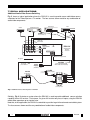
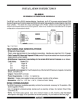
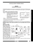
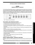
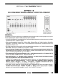
RS41AV PANEL DESCRIPTIONS
1. INPUT jacks. Connect to the corresponding output jacks of the source components (satellite receiver,
VCR, camcorder, laser disc player, TV surveillance camera, CD player, AM/FM tuner, cassette tape
deck, etc.).
2. OUTPUT jacks. Connect to the corresponding input jacks of AV receivers, TV monitors, VCRs, etc.
3. POWER 15VAC V V terminals. Connect the leads of the 15V AC Power Supply (included) to these
terminals (lead polarity is not required).
4. G and IR IN terminals. Input terminals for the IR control signal. Connect a 2-conductor cable from
the emitter or signal output port of any Xantech Connecting Block, IR receiver, Key Pad, or Controller
here. The positive lead connects to "IR IN" and the negative to "G".
5. IR CONFIRM LED. Lights continuously when power is applied. Flashes when RC68+ (and RC68)
IR commands are received.
6. Mounting Holes.
1
Remote Control Switchers
AUDIO
RIGHT
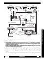
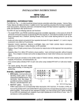
TYPICAL APPLICATIONS
Additional Audio/Video Source Switching
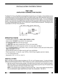
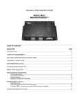
Fig. 2 shows a typical application where the RS41AV is used to provide more audio/video source
selections for the Video input on a TV monitor. The four sources shown could be any combination of
audio/video components.
V
L
DVD Player
Satellite Receiver
Game
V
R
L
V
R
L
VCR
V
R
L
R
283M Blink-IR™
Mouse Emitter (3)
RCA type
patch cords
1
2
3
4
RS41AV
VIDEO
IR
CONFIRM
RS41AV
POWER 15VAC V V G IR IN
Audio/Video
Remote
Switcher
REMOTE SWITCHER
®
AUDIO
LEFT
AUDIO
RIGHT
INPUT
OUTPUT
White stripped side
IR Signal
6015900
RCA type
patch cords
Power
Supply
(included)
291-00
IR Receiver
3.5mm to-stripped-ends
mono cable (not included)
To 120
V AC
To 120 V AC
(unswitched)
781RG
Power Supply
+12 VDC
IR IN
EMITTERS
MONITOR
®
R
GND
STATUS
789-44
TV
IR
RCVR
L
CONNECTING BLOCK
12VDC
V
789-44
Connecting Block
FIig 2 Additional Source Switching for a TV Monitor
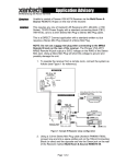
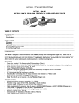
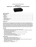
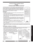
Similarly, Fig. 3 illustrates a system where the RS41AV is used to provide additional source selection
capability for an A/V receiver. For instance, if a given A/V receiver only has six inputs, using the RS41AV
would allow expansion up to a total of nine.
Note that, in this application, the RS41AV is controlled as part of a larger Infrared remote controlled system.
The four sources shown could be any combination of audio/video components.
2
RS41AV
CD Changer
L
V
R
L
VCR
DVD Player
Satellite Receiver
R
V
L
V
R
2
3
R
286M Dual Blink-IR™
RCA type
patch cords
1
L
Mouse Emitters (2)
4
RS41AV
VIDEO
IR
CONFIRM
RS41AV
POWER 15VAC V V G IR IN
Audio/Video
Remote
Switcher
REMOTE SWITCHER
®
AUDIO
LEFT
AUDIO
RIGHT
INPUT
OUTPUT
Power
Supply
IR Signal
White stripped side
(included)
RCA type
patch cords
R L
V
To 120 V AC
(switched)
AV
Receiver
781RG
Power Supply
+12 VDC
GND
STATUS
IR IN
®
IR
RCVR
TV
EMITTERS
3-wire cable from
additional IR
receivers, keypads,
etc. in other rooms,
if needed.
789-44
V
CONNECTING BLOCK
490-30 IR Receiver
R L
12VDC
Mouse Emitter (1)
MONITOR
789-44
Connecting Block
Fig. 3 Expanding the Source Switching of an AV Receiver
INSTALLATION
1. Code Groups: If more than one RS41AV is used in a given system, or it is included in an IR controlled
system with other Xantech products that respond to RC68+ commands, different code groups can be
assigned to avoid mutual interaction.
NOTE: As received from the factory, the RS41AV is set to code group 20. Refer to the RC68+
instructions for code group setting procedures.
2. Typically a programmable remote controller, such as a Xantech learning remote control or keypad, is
"taught" each of the RS41AV commands (from the RC68+, Fig.4) plus the specific input command for
the A/V receiver or TV monitor to which the RS41AV is connected. These commands are placed in
a "sequence" or "macro". A single key press will then select the desired source connected to the
RS41AV.
For "sequence" or "macro" programming, follow the instructions that come with the learning device
RS41AV
3
Remote Control Switchers
283M Blink IR™
To 120 V AC
(unswitched)
6015900
3.5mm to-stripped-ends
mono cable (not included)
IR LENS
3. The power supply for the RS41AV may be connected to the
switched AC outlet on the rear of an A/V receiver, if an A/V
receiver is used in the system.
2
4. Fig. 3 assumes the use of an A/V receiver having baseband
video switching capabilities.
A
B
C
ADJ-OFF
80
48
10
90
1
2
3
4
00
C0
5
50
6 INPUT 7
D0
A
01
41
8
40
A0
30
20
E0
70
TREBLE
BASS
Z-ADJ
60
88
18
B0
21
F0
61
GLOBAL
5. Use high quality low-loss cables for all A/V connections. For runs
in excess of 10 feet, use low-loss RG-6 coax..
VOL
98
09
MUTE
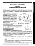
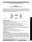
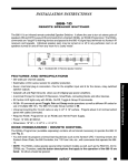
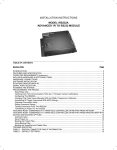
RC68+ PROGRAMMER/REMOTE
CONTROL
The RC68+ (and the RC68) programmer (availabel separately) contains the commands necessary to operate the RS41AV.
Use the commands 1, 2, 3, and 4 (item 2, Fig.4) to select the respective
four source inputs on the RS41AV.
1
08
A8
28
E8
E-FLAT
LAST
68
C8
OFF
E1
38
B8
ON
OFF
78
F8
MAX-V
TRIM
58
29
69
D8
49
A9
E9
C-BAL
89
C9
71
19
59
39
79
F1
99
D9
B9
F9
Fig 4 RC68 Handheld Programmer
(available separately)
RS41AV SPECIFICATIONS
AUDIO
Gain: . . . . . . . . . . . . . . . . . . . . . . . . . . . . . . . . . . . . . . . . . Unity
Input Overload: . . . . . . . . . . . . . . . . . . . . . . . . . . . . 3.0 V RMS
Input Impedance: . . . . . . . . . . . . . . . . . > 25k Ohms (ea. input)
Output Impedance: . . . . . . . . . . . . . . . . . . . . . . . . . . . 1k Ohms
THD: . . . . . . . . . . . . . . . . . . . . . . . . . 0.04% at 1.0 V input level
Freq. Response: . . . . . . . . . . . . . . . . . . 8 Hz - 50 kHz +/- 1 dB
Channel Separation:. . . . . . . . . . . . > 75 dB (100 Hz to 10 kHz)
Input to Input Isolation:. . . . . . . . . . > 85 dB (100 Hz to 10 kHz)
S/N Ratio ("A" WTD): . . . . . . . . . . . . . . . . . . 100 dB (re 2V out)
VIDEO
Gain: . . . . . . . . . . . . . . . . . . . . . . . . . . . . . . . . . . . . . . . . . Unity
Input Impedance: . . . . . . . . . . . . . . . . . . . . . . . . . . . . 75 Ohms
Output Impedance: . . . . . . . . . . . . . . . . . . . . . . . . . . .75 Ohms
Video Insertion Loss: . . . . . . . . . . . . . . 50 Hz - 10 MHz < 1 dB
OUT-IN Isolation: . . . . . . . . . . . . . . . . .50 Hz - 10 MHz > 55 dB
GENERAL
A/V inputs/outputs: . . . . . . . . . . . . . . . . RCA-type phono jacks
Power & IR Inputs: . . . . . . . . . . . . . . . . Screw Terminal Plug-In
Factory Preset IR Code Group: . . . . . . . . . . . . . . . . . . . . . . 20
Power Requirements: . . . . . . . . . . . . . . . . . 15V AC @ 300 mA (Power Supply included)
Dimensions: . . . . . . . . . . . . . . . . . . . .10" W x 3" D x 1 3/8" H
7-24-00
4
RS41AV