1
INSTALLATION INSTRUCTIONS
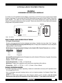
IR-DC4
IR/RS232 INTERFACE MODULE
DB9F RS232
OUTPUT PORT
IR-DC4
IR IN
IR GND
PWR GND
+12VDC
®
IR/RS232
INTERFACE MODULE
SYLMAR, CA
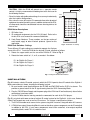
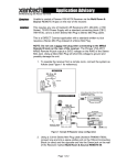
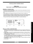
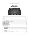
Fig. 1 The IR-DC4
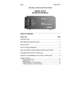
FEATURES AND SPECIFICATIONS
• IR Signal & Power Inputs:
Plug-in screw-type terminals for four-conductor connections. Handles wire sizes from 24 to 12 gauge.
• Opto-Coupled IR IN Input and Separate IR Gnd permits IR input to be isolated from chassis and power
supply grounds, where needed.
• RC68 Remote Programmer Code Settings for the Arrakis DC4 Control Protocols are as follows:
Code Setting
Arrakis DC4
D-1
Player #1
D-2
Player #2
D-3
Player #3
• Accepts IR control signals from the IR outputs of any of the Xantech IR Receivers, Keypads, Connecting
Blocks, Controllers, etc.
• Output: RS232 DB9F connector.
• Power Requirements: 12 VDC ± 1.5 V @ 20 mA.
• Mounting: Flanges, plus supplied screws, permit easy mounting to flat surfaces.
• Dimensions: 4-3/8" L x 1-7/8" W x 1-1/4" H (110mm x 47mm x 32mm)
RC68 PROGRAMMER
The RC68 Programmer (available separately) contains the commands necessary for IR operation of the
DC4 through the IR-DC4.
• Use it to program universal learning devices such as learning remotes, the Xantech Smart Pads,
Controllers, etc.
• NOTE: The RC68 codes operate many other Xantech models as well, therefore, only the button
descriptions that apply to the operation of the DC4 (Overlay "F") are listed on the next page.
1
Modules & Connecting Blocks
The IR-DC4 is an IR to RS232 Interface Module. Specifically, the IR-DC4 converts certain Xantech RC68
Remote Programmer IR control codes into RS232 commands that operate the Arrakis Digilink 4 Hard Disk
Audio Jukebox. This allows the unique advantages of the Arrakis Jukebox to be easily integrated into
Xantech IR-controlled whole house music systems. Refer to the Arrakis DC4 Users Manual for complete
configuration and operational details.
CAUTION: While the RC68 will operate as a separate remote
control, it is highly recommended it not be given to the final user for
the following reasons:
1
ROW
NUMBERS
• Since it includes adjustable code settings, the user may inadvertently
alter the installer configurations.
• Also, since the user will require IR commands from other brands of
equipment to control the total system, in addition to those of the DC4,
all commands should be consolidated into one learning device, for
ease of use.
B
C
48
01
90
1
1
2
2
3
3
PLAY
4
00
C0
50
4
5
5 INPUT 6
6
7
3
40
A0
30
B0
7
8
9
GLOBAL
PAUSE
4
20
E0
70
F0
CD#
TREBLE
0
BASS
TR#
Z-ADJ
RESUME
VOLUME
2
5
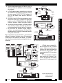
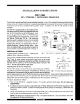
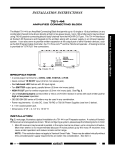
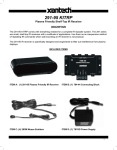
RC68 Button Descriptions
F
A
10
1
60
88
18
DISC --
DISC +
TR --
D0
STOP
8
Place the
"F"
Overlay
on the
RC68
98
2
TR +
MUTE
6
1. IR Emitter Lens.
08
A8
38
B8
1 CD
ALL CD
ON
SEQL
OFF
RANDOM
7
2. IR command assignments for the DC4 (32 total). Refer to the
Arrakis DC4 users manual for command definitions.
E8
78
F8
TITLE
LAST
NUMBER
MAX-V
ZONE
TRIM
8
3. Code Group Numbers. These numbers, on the top surface of
each button, apply to other Xantech products. Ignore for this
application.
3
28
ARTIST
E-FLAT
68
C8
58
D8
LEFT
OFF
RIGHT
ENTER
BALANCE
SELECT
RC68 PROGRAMMER
Fig. 2 RC68 with "F" Overlay
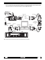
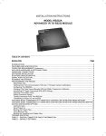
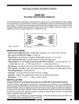
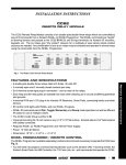
RC68 Code Switches - Settings
Three different IR code settings are needed to operate the 3 player
zones of the DC4. To set the RC68 for the desired IR code, proceed as follows:
1. Rotate the upper switch, on the rear of the RC68 to D. Refer to Fig. 3.
2. Rotate the lower switch to 1, 2, or 3, as needed. See below:
D-1 for Digilink 4's Player 1
BC
F 012
9
78 A
D-3 for Digilink 4's Player 3
3456
F 012
9
78 A
9
78 A
48
9
78 A
10
3456
D
BC E
F 012
2nd Digit
(lower)
01
3456
D
BC E
D
BC E
F 012
1st Digit
(Upper)
3456
DE
RC68
(back
side)
D-2 for Digilink 4's Player 2
90
Fig. 3 Setting the RC68 Code Switches
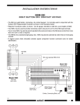
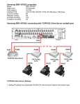
INSTALLATION
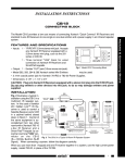
Fig. 4 illustrates a basic IR control system in which the IR-DC4 permits direct IR control of the Digilink 4.
Make connections as shown, keeping the following in mind:
1. Be sure to add a small jumper between the IR GND and PWR GND on the IR-DC4 as shown. This
provides a ground return for the IR signal coming from the CB12 Connecting Block.
2. Plug the 781RG Power Supply and the power plug of the DC4 into AC wall outlets only after all other
connections have been made.
3. Use the RC68 to teach a learning remote the commands for each of the DC4 players.
Fig. 5 is a typical multi-room version of a direct IR control system for the Digilink 4. In this case, Xantech
Smart Pad2 keypads are used as well as IR receivers. The system is configured as follows:
1. The DC4 is the audio music source in the system using an A/V receiver, along with other A/V sources.
2. A 789-44 four-output Connecting Block is used so that other system components can be IR controlled
in addition to the DC4. If even more components need to be controlled, a ten-output amplified
connecting block, model 791-44, could be used.
2
IR-DC4
3. A high current power supply, the 782-00 (1A @ 12
VDC), provides the additional current needed for
the keypads.
291-80 IR Receiver
Hand Held
Remote
4. A 786-00 power supply, plugged into a switched
AC outlet on the A/V receiver, is used as a source
of system power ON/OFF STATUS voltage (12
VDC) for the Smart Pad2s and the 780-80 IR
Receiver.
781RG
To 120 V AC
(unswitched)
REMOTE ROOM 3
+12VDC
®
S
780-80
PWR OUT
V G
®
SYLMAR, CA 91342
IR RECEIVER
780-80
+12V
STATUS
GND
IR OUT
IR OUT
IR
RCVR
Standard DB9 9-pin Cable
(DB9M-to-DB9F)
Connect to an
RS232 Port (#1 or 3)
on rear panel
DC4
HARD DISK AUDIO JUKEBOX
Fig. 4 Direct IR Control of the DC4 using the IR-DC4
CB12
Connecting Block
291-80
X
J-Box
IR Receiver
(rear view)
+12V
Hidden Link™
IR Receiver
7 Foot Quick
Connect Cable
STATUS
GND
IR OUT
Satellite Receiver
IR OUT
+12V
GND
STATUS
IR OUT
+12V
GND
STATUS
120 V AC
(Unswitched)
782-00
283M
Power
Supply
Smart
Pad™
Blink IR™
VCR
IR OUT
+12V
GND
STATUS
789-44
Connecting Block
283M
Blink IR™
Plug into
Switched
AC Outlet
on A/V
Receiver
(see text)
AV Receiver
IR IN
EMITTERS
+
IR
RCVR
White
Striped
Side
("+")
®
–
789-44
GND
STATUS
CONNECTING BLOCK
12VDC
+12 VDC
SYLMAR, CA
GND Jumper
REMOTE ROOM 4
+12V
GND
STATUS
Resistor.
See item 5
below
IR/RS232
INTERFACE MODULE
PWR GND
Fig. 6 illustrates how the IR-DC4 is connected to
provide IR control of a Digilink 4 via a PC running the
Arrakis Music-Link Software (Win 95/98). The following should be considered when working with this configuration:
Smart
Pad™
V G S
IR GND
283M
Blink IR™
Mouse Emitter
786-00
Power Supply
(12V at 10 mA)
1. Fig. 6 shows a single 29180 IR Receiver as the IR control
source. Multi-room, whole house
systems with many keypads and
IR receivers may also be used,
connected to the IR-DC4, as shown
in Fig. 5.
2. The Arrakis Music-Link Software permits the in-room IR receivers and keypads to remotely
operate the PC, and through it, the
Mono Mini Plug to Stripped
Ends, 2-Conductor Cable,
Xantech Pt #6015900
White Striped Side
IR-DC4
IR IN
IR GND
PWR GND
+12VDC
®
IR/RS232
INTERFACE MODULE
SYLMAR, CA
Standard DB9 Cable
(DB9M-to-DB9F)
Connect to an
RS232 Port (#1 or 3)
on rear panel
DC4
Fig. 5 Multi-Room Direct
Control of the DC4
using the IR-DC4
HARD DISK AUDIO JUKEBOX
IR-DC4
3
Modules & Connecting Blocks
IR-DC4
IR IN
7. An RC68 and the Xantech Dragon DropIR™
software are used to program the Smart Pad2
keypads with the DC4 player commands and the
A/V system commands.
REMOTE ROOM 2
IR
RCVR
CB12 Connecting Block
(Included with the 291-80)
6. As with the previous example, an RC68 is used to
teach learning remotes (used with the IR receivers) the commands for each of the DC4 players.
Smart
Pad™
3-Conductor
Cable
PWR OUT
5. A resistor (1k to 10k Ohm) may be added in series
with the STATUS line, if desired, to adjust the
brightness of the STATUS LED in the 780-80 IR
Receiver. Refer to "REMOTE ROOM 3", Fig. 5.
REMOTE ROOM 1
7-Foot 3Conductor
Cable
Power Supply
DC4. For details of the many operational functions and configuration options for the Arrakis system,
refer to the Arrakis DC4 users manual and DC4 Series Application Notes.
291-80 IR Receiver
DB9 Cable
GND Jumper
V G S
PWR OUT
IR
RCVR
IR-DC4
IR IN
IR GND
IR/RS232
INTERFACE MODULE
PWR GND
+12VDC
®
SYLMAR, CA
CB12 Connecting Block
(Included with the 291-80)
To 120 V AC
(unswitched)
Null Modem
Adapter or Adapter
Cable
DB9 Cable
781RG
Connect to 1st
Serial Port
Power Supply
Connect to 2nd
Serial Port
PC
Connect to
RS232 Port #4
on rear panel
DB9 Cable
DC4
HARD DISK AUDIO JUKEBOX
Fig. 6 Control of the DC4 using an IR-DC4 and a PC with Arrakis Music-Link Software
5-10-00
4
IR-DC4