1
ISP-100
INTEGRATED SIGNAL
PROCESSOR
Users Manual
THIS PAGE LEFT BLANK
INTENTIONALLY
i
PROPRIETARY NOTICE
The Merlin product information and design disclosed herein were originated by and are the property of Telex
Communications, Inc. Telex reserves all patent, proprietary design, manufacturing, reproduction, use and
sales rights thereto, and to any article disclosed therein, except to the extent rights are expressly granted to
others.
PATENT NOTICE
This equipment contains and uses a design for which patent applications have been made. Patents Pending.
COPYRIGHT NOTICE
Copyright 1997-98 by Telex communications, Inc. all rights reserved. Reproduction in whole or in part without
prior written permission from Telex is prohibited.
NOTICE TO USER
This manual should not be construed as any representation or warranty with respect to the software named
herein. Occasionally changes or variations exist in the software that are not reflected in the manual.
Generally, if such changes or variations are known to exist and to affect the product significantly, a release
note or README file accompanies the manual and the distribution disks. In that event, be sure to read the
release note or README file before using the product.
This publication could include technical inaccuracies or typographical errors. Changes are periodically made
to the information herein; these changes will be incorporated in new editions of the publication. TELEX
Communications may make improvements and/or changes in the product(s) and/or program(s) described in
this publication at any time.
TRADEMARKS
VUE-IT™ and Virtual User Environmental for InterActive Technology™ are trademarks of TELEX
Communications. Windows®, Windows 3.1®, Windows 3.11®, Windows 95®, and MS-DOS® are all
trademarks of Microsoft Corporation. Names of other products mentioned herein are used for identification
purposes only and may be trademarks and/or registered trademarks of their respective companies.
UNPACKING AND INSPECTION
Immediately upon receipt of the equipment, inspect the shipping container and the contents carefully for any
discrepancies or damage. Should there be any, notify the freight company and the dealer at once.
WARRANTY INFORMATION
Merlin products are warranted by Telex Communications, Inc. to be free from defects in materials and
workmanship for a period of three years from the date of sale.
The sole obligation of Telex during the warranty period is to provide, without charge, parts and labor
necessary to remedy covered defects appearing in products returned prepaid to Telex. This warranty does
not cover any defect, malfunction or failure caused beyond the control of Telex, including unreasonable or
negligent operation, abuse, accident, failure to follow instructions in the manual, defective or improper
associated equipment, attempts at modification and repair not authorized by Telex, and shipping damage.
Products with their serial numbers removed or effaced are not covered by this warranty.
To obtain warranty service, follow the procedures entitled “Procedure for Returns” and “ Shipping to
Manufacturer for Repair or Adjustment”.
This warranty is the sole and exclusive express warranty given with respect to Merlin products. It is the
responsibility of the user to determine before purchase that this product is suitable for the user’s intended
purpose.
General Information
ii
ANY AND ALL IMPLIED WARRANTIES, INCLUDING THE IMPLIED WARRANTY OF MERCHANTABILITY
ARE LIMITED TO THE DURATION OF THIS EXPRESS LIMITED WARRANTY.
NEITHER TELEX NOR THE DEALER WHO SELLS MERLIN PRODUCTS IS LIABLE FOR INCIDENTAL
OR CONSEQUENTIAL DAMAGES OF ANY KIND.
CUSTOMER SUPPORT
Technical questions should be directed to:
Customer Service Department
Merlin/Telex
9600 Aldrich Avenue South
Minneapolis, MN 55420 U.S.A.
Telephone: (612) 884-4051
Fax: (612) 884-0043
RETURN SHIPPING INSTRUCTIONS
Procedure for Returns
If a repair is necessary, contact the dealer where this unit was purchased.
If repair through the dealer is not possible, obtain a RETURN AUTHORIZATION from:
Customer Service Department
Telex Communications, Inc.
Telephone: 1-800-828-6107 or (612) 884-4051 extension 425 or 420
Fax: 1-800-323-0498 or (612) 884-0043
DO NOT RETURN ANY EQUIPMENT DIRECTLY TO THE FACTORY WITHOUT FIRST OBTAINING A
RETURN AUTHORIZATION.
Be prepared to provide the company name, address, phone number, a person to contact regarding the repair,
the type and quantity of equipment, a description of the problem and the serial number(s).
Shipping to Manufacturer for Repair or Adjustment
All shipments of Merlin products should be made via United Parcel Service or the best available shipper
prepaid. The equipment should be shipped in the original packing carton; if that is not available, use any
suitable container that is rigid and of adequate size. If a substitute container is used, the equipment should be
wrapped in paper and surrounded with at least four inches of excelsior or similar shock-absorbing material. All
shipments must be sent to the following address and must include the Return Authorization.
Factory Service department
Telex Communications, Inc.
West 1st Street
Blue Earth, MN 56013 U.S.A.
Upon completion of any repair the equipment will be returned via United Parcel Service or specified shipper
collect.
10 July 1998
iii
End-User License Agreement for Telex® Software
IMPORTANT – Please read this document carefully before using this product.
THIS DOCUMENT STATES THE TERMS AND CONDITIONS UPON WHICH TELEX COMMUNICATIONS,
INC. (the “COMPANY”) OFFERS TO LICENSE THE INSTALLED SOFTWARE OR PROGRAM (the
“SOFTWARE”) FOR USE WITH THE PRODUCT IN WHICH IT WAS INSTALLED. YOU ARE AGREEING
TO BECOME BOUND BY THE TERMS OF THIS AGREEMENT. IF YOU DO NOT AGREE TO THE TERMS
OF THIS AGREEMENT, DO NOT USE THIS PRODUCT. PROMPTLY RETURN THE PRODUCT TO THE
PLACE WHERE YOU OBTAINED IT FOR A FULL REFUND.
The installed Software as supplied by the Company is licensed, not sold, to you for use only under the terms
of this license, and the Company reserves all rights not expressly granted to you. You own the product or
other media on or in which the Software was originally or subsequently recorded or fixed, but the Company
retains ownership of all copies of the Software itself.
1. License: This license allows you to use the Software for internal purposes only on a single product in which
it was installed.
2. Restrictions:
(a) You may not market, distribute or transfer copies of the Software to others or electronically
transfer or duplicate the Software. YOU MAY NOT REVERSE ENGINEER, DECOMPILE,
DISASSEMBLE, MODIFY, ADAPT, TRANSLATE, RENT, LEASE OR LOAN THE SOFTWARE OR
CREATE DERIVATIVE WORKS BASED ON THE SOFTWARE OR ANY ACCOMPANYING
WRITTEN MATERIALS.
(b) The Software and the accompanying written materials are copyrighted. Unauthorized copying of
the Software, including portions thereof or the written materials, is expressly forbidden.
(c) You understand that the Company may update or revise the Software and in so doing incurs not
obligation to furnish such updates to you.
3. Limited Warranty: The Company does not warranty that the operation of the Software will meet your
requirements or operate free from error. THE COMPANY DISCLAIMS ALL OTHER WARRANTIES AND
CONDITIONS EITHER EXPRESSED OR IMPLIED, INCLUDING THE WARRANTIES OF
MERCHANTABILITY, FITNESS FOR A PARTICULAR PURPOSE AND NON-INFRINGEMENT OF THIRD
PARTY RIGHTS.
4. Limited Liability: The liability of the Company for any claims arising out of this License based upon the
Software, regardless of the form of action, shall not exceed the greater of the license fee for the Software or
$50.
General Information
iv
Table of Contents
INTRODUCTION .................................................................... 1-1
An Overview of the ISP-100 ................................................................................................
About this Manual ................................................................................................................
Customer Support ...............................................................................................................
Conventions Used in this Manual ........................................................................................
1-1
1-2
1-2
1-2
SETUP & INSTALLATION ...................................................... 2-1
Introduction..........................................................................................................................
Unpacking ...........................................................................................................................
Front Panel Features ...........................................................................................................
Rear Panel Features ...........................................................................................................
Power Requirements ...........................................................................................................
Operating Environment .......................................................................................................
Rack Mounting ....................................................................................................................
Card Installation Procedure .................................................................................................
Cable Diagrams...................................................................................................................
Analog Audio .................................................................................................................
Digital Audio ..................................................................................................................
Serial Communications .................................................................................................
General Purpose Inputs (GPI) .......................................................................................
Master Sync Input .........................................................................................................
2-1
2-1
2-1
2-2
2-2
2-2
2-2
2-3
2-4
2-4
2-5
2-6
2-9
2-9
TROUBLESHOOTING ............................................................ 3-1
User Modifications ............................................................................................................... 3-1
In Case of Problems ............................................................................................................ 3-1
Diagnostics .......................................................................................................................... 3-2
Factory Default Mode .......................................................................................................... 3-2
Retrieving Version Numbers ............................................................................................... 3-3
Retrieving Serial Numbers .................................................................................................. 3-3
Changing the Fuse .............................................................................................................. 3-4
Changing the Battery ........................................................................................................... 3-4
Technical Support ............................................................................................................... 3-6
Procedure for Returns ......................................................................................................... 3-6
Shipping to Manufacturer for Repair or Adjustment ............................................................ 3-7
SPECIFICATIONS .................................................................. 4-1
Components ........................................................................................................................
Compressor ...................................................................................................................
Crossover ......................................................................................................................
Delay .............................................................................................................................
Dither .............................................................................................................................
Gain ...............................................................................................................................
Gate ...............................................................................................................................
Limiter ............................................................................................................................
Filters .............................................................................................................................
10 July 1998
4-1
4-1
4-1
4-1
4-1
4-1
4-1
4-2
4-2
v
Table of Contents
LowPass Filter ........................................................................................................... 4-2
HighPass Filter .......................................................................................................... 4-2
AllPass Filter.............................................................................................................. 4-2
LowShelf Filter ........................................................................................................... 4-2
HighShelf Filter .......................................................................................................... 4-2
Notch Filter ................................................................................................................ 4-2
PEQ ........................................................................................................................... 4-3
Combine ........................................................................................................................ 4-3
Input .............................................................................................................................. 4-3
Output ............................................................................................................................ 4-3
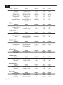
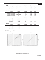
ISP-100 Component Plots ................................................................................................... 4-3
Compressor ................................................................................................................... 4-3
Limiter ............................................................................................................................ 4-3
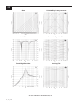
Gate ............................................................................................................................... 4-4
Linkwitz-Riley 3-way Crossover .................................................................................... 4-4
Notch Filter .................................................................................................................... 4-4
Parametric Equalizer Filter ............................................................................................ 4-4
Peaked HighPass Filter ................................................................................................. 4-4
Shelving Filter ................................................................................................................ 4-4
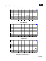
System Measurements ........................................................................................................ 4-5
System Frequency Response ....................................................................................... 4-5
System Noise Floor ....................................................................................................... 4-5
System THD+N ............................................................................................................. 4-5
MIM-1 & MIM-2 Analog Input Modules ................................................................................ 4-6
Power ............................................................................................................................ 4-6
Performance .................................................................................................................. 4-6
Miscellaneous ................................................................................................................ 4-6
Notes ............................................................................................................................. 4-6
MOM-1 Analog Output Module ............................................................................................ 4-7
Power ............................................................................................................................ 4-7
Performance .................................................................................................................. 4-7
Miscellaneous ................................................................................................................ 4-7
Notes ............................................................................................................................. 4-7
MDM-1 AES/EBU Digital I/O Module ................................................................................... 4-8
Power ............................................................................................................................ 4-8
Performance (Sample Rate Converter Engaged) ......................................................... 4-8
Performance (Sample Rate Converter Bypassed) ........................................................ 4-9
Miscellaneous ................................................................................................................ 4-9
Notes ........................................................................................................................... 4-10
Physical ............................................................................................................................. 4-10
Height .......................................................................................................................... 4-10
Width ........................................................................................................................... 4-10
Depth ........................................................................................................................... 4-10
Weight ......................................................................................................................... 4-10
Included Accessories .................................................................................................. 4-10
Power ................................................................................................................................ 4-10
General Information
vi
Table of Contents
INSTALLING VUE-IT ........................................................... 5-1
Minimum System Requirements .........................................................................................
Identifying a Serial Port .......................................................................................................
Loading the Software ..........................................................................................................
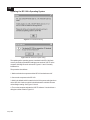
Updating the ISP-100’s Operating System ..........................................................................
Configuring the Software .....................................................................................................
5-1
5-1
5-1
5-2
5-4
GETTING STARTED............................................................... 6-1
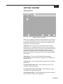
Starting VUE-IT ...................................................................................................................
Starting a New Project .........................................................................................................
VUE-IT File System .............................................................................................................
Archiving Projects ..........................................................................................................
Mounting Projects ..........................................................................................................
QuickMAP Template Files .............................................................................................
Component Directory ....................................................................................................
Operating System (OS) Files ........................................................................................
6-1
6-2
6-3
6-4
6-4
6-4
6-4
6-4
USING VUE-IT ....................................................................... 7-1
File ......................................................................................................................................
New Project ...................................................................................................................
Open Project .................................................................................................................
Save ..............................................................................................................................
Save As .........................................................................................................................
Activate Project Manager ..............................................................................................
Activate QuickSET Manager .........................................................................................
Exit ................................................................................................................................
Most Recently Used Files ..............................................................................................
Edit ......................................................................................................................................
Cut .................................................................................................................................
Copy ..............................................................................................................................
Paste .............................................................................................................................
Tools ...................................................................................................................................
Refresh Directories ........................................................................................................
Scan ..............................................................................................................................
Options ................................................................................................................................
Preferences ...................................................................................................................
System Configurations ..................................................................................................
Window ...............................................................................................................................
Cascade ........................................................................................................................
Tile .................................................................................................................................
Arrange Icons ................................................................................................................
Help .....................................................................................................................................
About .............................................................................................................................
Preferences .........................................................................................................................
Soft Mute Ramp in ms ...................................................................................................
Display Recently Opened Files in the File Menu ...........................................................
10 July 1998
7-1
7-1
7-1
7-1
7-1
7-1
7-1
7-1
7-1
7-2
7-2
7-2
7-2
7-2
7-2
7-2
7-2
7-2
7-2
7-3
7-3
7-3
7-3
7-3
7-3
7-3
7-3
7-4
vii
Table of Contents
OpenDevice Status Panel on Error ............................................................................... 7-4
Display QuickMAP Pop-Up names ................................................................................ 7-4
Display Filter Bandwidth in “Q” ...................................................................................... 7-4
System Configurations ........................................................................................................ 7-4
New Projects ................................................................................................................. 7-4
Component Library ........................................................................................................ 7-4
QuickMAP Library ......................................................................................................... 7-5
Company Name ............................................................................................................ 7-5
Designer’s Name ........................................................................................................... 7-5
Communications ............................................................................................................ 7-5
Default Preference ........................................................................................................ 7-5
Project Manager .................................................................................................................. 7-5
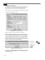
Properties for the ISP-100 ............................................................................................. 7-6
Project Properties .......................................................................................................... 7-7
QuickMAP Selection ...................................................................................................... 7-7
QuickMAP Properties .................................................................................................... 7-8
Component Properties .................................................................................................. 7-8
Component Export ........................................................................................................ 7-9
Component Import ....................................................................................................... 7-10
QuickSET Manager ........................................................................................................... 7-10
Creating New QuickSETs ............................................................................................ 7-11
Deleating QuickSETs .................................................................................................. 7-11
Selecting the Active QuickSET .................................................................................... 7-11
Updating a QuickSET .................................................................................................. 7-11
Discarding Changes .................................................................................................... 7-11
GPI .................................................................................................................................... 7-11
Configuring Input Pins ................................................................................................. 7-11
Testing the GPI Assignments ...................................................................................... 7-12
QuickMAP ......................................................................................................................... 7-13
QuickMAP Component Bypassing .............................................................................. 7-13
I/O Properties .................................................................................................................... 7-14
Input ............................................................................................................................ 7-14
Output .......................................................................................................................... 7-15
Digital I/O ..................................................................................................................... 7-15
Status Information ................................................................................................... 7-16
Device Status Panel .......................................................................................................... 7-17
Clock Sync .................................................................................................................. 7-17
Digital Data .................................................................................................................. 7-17
Low Battery ................................................................................................................. 7-17
Input Clip ..................................................................................................................... 7-17
Process Clip ................................................................................................................ 7-17
Output Meters .................................................................................................................... 7-18
PROCESSING COMPONENTS ............................................... 8-1
Combine .............................................................................................................................. 8-2
Input Attenuators ........................................................................................................... 8-2
Fine (F) or Coarse (C) Control ...................................................................................... 8-3
General Information
viii
Table of Contents
Polarity Control (+/-) ...................................................................................................... 8-3
Mute Control (M) ........................................................................................................... 8-3
Bypass Control (master) ................................................................................................ 8-3
Compressor ......................................................................................................................... 8-4
Familliar Controls .......................................................................................................... 8-4
Unfamiliar Controls ........................................................................................................ 8-6
Metering ........................................................................................................................ 8-8
Notes on Operation of the Compressor ......................................................................... 8-8
Meter ............................................................................................................................. 8-9
Threshold ...................................................................................................................... 8-9
Attack, Window, Release, and Crest Factor Controls ................................................... 8-9
Fine (F) or Coarse (C) Control .................................................................................... 8-10
Knee Control ............................................................................................................... 8-10
Ratio Control ............................................................................................................... 8-10
Sidechain ..................................................................................................................... 8-10
Bypass Control (master) .............................................................................................. 8-10
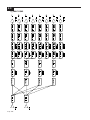
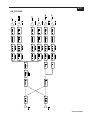
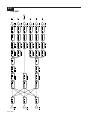
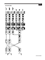
Crossover .......................................................................................................................... 8-11
Two-Way Crossovers .................................................................................................. 8-11
Three-Way Crossovers ............................................................................................... 8-13
Four-Way Crossovers ................................................................................................. 8-17
Sum-to-Allpass Characteristics of Linkwitz-Riley Crossovers ..................................... 8-20
Low, Low-Mid, Mid, Mid-High, and High Controls ....................................................... 8-21
Link/Unlink Control ...................................................................................................... 8-21
Slope ........................................................................................................................... 8-21
Class ........................................................................................................................... 8-22
Cutoff Frequency ......................................................................................................... 8-22
Passband Gain ............................................................................................................ 8-22
Fine (F) or Coarse (C) Control .................................................................................... 8-23
Polarity Control (+/-) .................................................................................................... 8-23
Mute Control (M) ......................................................................................................... 8-23
Cut ..................................................................................................................................... 8-24
Attenuation and Polarity .............................................................................................. 8-24
Bypass ......................................................................................................................... 8-24
Attenuator .................................................................................................................... 8-24
Fine (F) or Coarse (C) Control .................................................................................... 8-25
Polarity Control (+/-) .................................................................................................... 8-25
Mute Control (M) ......................................................................................................... 8-25
Bypass Control (master) .............................................................................................. 8-25
Delay ................................................................................................................................. 8-26
Setting Delay ............................................................................................................... 8-26
Fine (F) or Coarse (C) Control .................................................................................... 8-26
Bypass Control (master) .............................................................................................. 8-26
Dither ................................................................................................................................. 8-27
Bit Level ....................................................................................................................... 8-27
Dither Signal Characteristics ....................................................................................... 8-32
Bypass ......................................................................................................................... 8-28
Dither Bit Level ............................................................................................................ 8-28
10 July 1998
ix
Table of Contents
Bypass Control (master) ..............................................................................................
Filter ..................................................................................................................................
Filter Bands .................................................................................................................
LowPass Filters ...........................................................................................................
HighPass Filters ..........................................................................................................
LowShelf Filters ...........................................................................................................
HighShelf Filters ..........................................................................................................
Notch Filters ................................................................................................................
Parametric EQ Filters ..................................................................................................
Peaked HighPass Filters .............................................................................................
AllPass Filters ..............................................................................................................
Filter Type ...................................................................................................................
Active Band .................................................................................................................
Bypass .........................................................................................................................
Bypass Control (master) ..............................................................................................
Frequency in Hz ..........................................................................................................
Boost/Cut .....................................................................................................................
Bandwidth ....................................................................................................................
Using the Magnitude (Mag.) or Phase Control ............................................................
Using the Logarithmic (Log.) or Linear Control............................................................
Using the 24 dB, 40 dB, 120 dB Controls ....................................................................
Gain Trim .....................................................................................................................
Fine (F) or Coarse (C) Control ....................................................................................
Isolate (Iso) Control .....................................................................................................
Polarity Control (+/-) ....................................................................................................
Gain ...................................................................................................................................
Metering ......................................................................................................................
Gain and Polarity .........................................................................................................
Bypass .........................................................................................................................
Metering ......................................................................................................................
Master Attenuator ........................................................................................................
Fine (F) or Coarse (C) Control ....................................................................................
Polarity Control (+/-) ....................................................................................................
Mute Control ................................................................................................................
Pre-Fader Metering (PFM) ..........................................................................................
Gate ..................................................................................................................................
Familiar Controls .........................................................................................................
Unfamiliar Controls ......................................................................................................
Metering ......................................................................................................................
Notes on Operation of the Gate ...................................................................................
Metering ......................................................................................................................
Attenuation and Threshold Controls ............................................................................
Open, Window, and Close Controls ............................................................................
Key Channel ................................................................................................................
Fine (F) or Coarse (C) Control ....................................................................................
Bypass Control (master) ..............................................................................................
Limiter................................................................................................................................
8-28
8-29
8-29
8-30
8-30
8-31
8-31
8-32
8-32
8-34
8-35
8-35
8-35
8-35
8-35
8-35
8-36
8-36
8-37
8-37
8-37
8-37
8-38
8-38
8-38
8-39
8-39
8-39
8-39
8-40
8-40
8-40
8-40
8-40
8-40
8-42
8-42
8-43
8-44
8-44
8-44
8-44
8-45
8-45
8-45
8-45
8-46
General Information
x
Table of Contents
Familiar Controls .........................................................................................................
Unfamiliar Controls ......................................................................................................
Notes on Operation of the Limiter ................................................................................
Meter ...........................................................................................................................
Threshold ....................................................................................................................
Attack, Window, Release, and Crest Factor Controls .................................................
Fine (F) or Coarse (C) Control ....................................................................................
Knee Control ...............................................................................................................
Bypass Control (master) ..............................................................................................
Select ................................................................................................................................
Selecting the Input .......................................................................................................
8-46
8-48
8-49
8-50
8-50
8-51
8-51
8-51
8-51
8-52
8-52
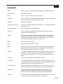
GLOSSARY ............................................................................A-1
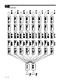
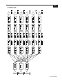
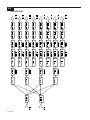
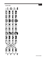
STANDARD QUICKMAP LIBRARY ......................................B-1
10 July 1998
1-1
INTRODUCTION
An Overview of the ISP-100
Thank you for choosing the ISP-100™ for your signal processing needs.
The ISP-100 is the first in a line of high quality signal processing
products from TELEX Communications, Inc.’s Merlin division. The
ISP-100 represents a continued commitment to understanding and
meeting our customers needs through the development of innovative and
intuitive solutions.
The ISP-100 is designed with flexibility in mind, which results in a
powerful tool that allows you to adapt to ever-changing markets and
applications. The utmost in quality is also a prime directive in the design
and manufacture of this product.
A series of predefined signal path topologies called QuickMAPs™ are
offered which enable the designer to quickly define the system’s
processing structure. This approach allows for a continuation of new
processing solutions and/or variations that provide “market specific”
templates to help minimize your design time and increase your profit.
This single rack space unit can replace a multitude of traditional analog
components. Time and money savings are realized in reduced labor
costs for wire harnessing, rack size, assembly, and minimized failure due
to reduced interconnection. As a result of this consolidation of
processing, overall system performance and audio integrity is greatly
increased.
An ergonomically designed software interface called VUE-IT™ provides
graphic control panels with the conventional look of signal processors, as
well as an advanced and easy to use filter tool panel which graphically
displays the configuration of your filter block settings.
The four in eight out
configuration is only
possible when the
second card slot
contains a digital
I/O card.
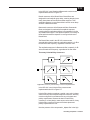
One of the most impressive and unique features of the ISP-100 is the
configurable input/output (I/O). This feature allows the designer or
installer to select between analog input or output modules, and/or a
digital input/output combination module. These modules are two channel
units and can be intermixed between analog and digital, thus providing a
variety of I/O combinations. The ISP-100 supports a maximum of four
inputs and eight outputs. The inputs and outputs can be either analog,
digital, or a combination of both.
Because of our commitment to providing the utmost in audio quality the
dynamic range of the ISP-100 rivals anything currently on the market.
The ISP-100 has a typical noise floor of –110 dBu and a typical THD+N
of <0.004%. Propagation time is minimized in the ISP-100. No more than
two milliseconds of delay is introduced from any analog input to analog
output with full processing and delay set to zero.
The ISP-100 is flexible. A General Purpose Interface (GPI) allows
multiple system configurations to be selected without the need of a PC to
control the unit. This is accomplished through user-supplied contact
Introduction
1-2
closures. This interface allows users to change system settings directly
and/or scroll through various settings.
About this Manual
This manual is covers the installation and operation of the ISP-100’s
hardware and software.
The ISP-100 has been designed to be as user-friendly as possible.
However, this manual should be read before attempting to install or
operate the ISP-100.
Customer Support
Be sure to fill out the customer support registration card included in the
software envelope. This will register you in our database of users.
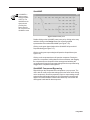
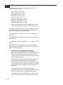
Conventions Used in this Manual
The margins in this manual include space for icons that provide
additional information to the user. The icons and their uses are given in
Table 1-1.
Table 1-1 Information icons.
10 July 1998
2-1
SETUP & INSTALLATION
Introduction
This section details the setup and installation of the MERLIN ISP-100.
Information is provided on the following: front and rear panel features,
physical requirements, installation of expansion cards, signal
connections for audio, data, and control.
Unpacking
Save the shipping
carton in case the
ISP-100 needs to be
returned for service.
The shipping carton is specially designed to protect the ISP-100 while
transporting under normal conditions. It is still possible for damage to
occur. Therefore, carefully inspect the outside carton for signs of abuse.
If for any reason the ISP-100 should need to be returned, use the
shipping carton that it came in. TELEX Communications, Inc. cannot
warranty against damage that occurs as a result of improper packaging.
The shipping box should contain the following items:
ISP-100
User’s Manual
VUE-IT Software Package
Spare Fuses (2)
Label Paper
IEC Power Cord
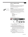
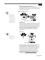
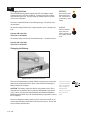
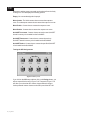
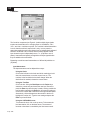
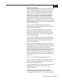
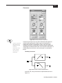
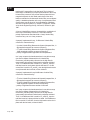
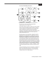
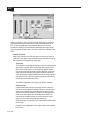
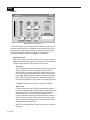
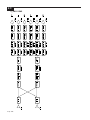
Front Panel Features (see Figure 2-1)
Figure 2-1 ISP-100 front panel features.
1. Label Holder—Provides a space to indicate the assignments of the
input and output modules.
2. Status LEDs—Provides power on/off, low battery, module presence,
signal clipping, and host communication status.
3. RS-232 Port—Links the PC to the unit via a DB-9 female connector.
4. RS-232 Selector—Selects between the front panel DB-9 port and the
rear panel RJ-45 port. Placing the switch in the down position
selects the DB-9 port located on the front of the unit. Placing the
switch in the up position selects the RJ-45 port located on the
rear of the unit.
5. Battery—Provides memory backup power. The expected life is
approximately four years.
6. Default Switch—Used to place unit in OS download request mode.
7. Fuse—Protects the power supply.
8. Power—Turns the unit on and off. Placing the switch in the down
position turns the unit on. Placing the switch in the up position
turns the unit off.
Setup & Installation
2-2
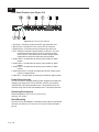
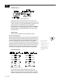
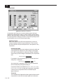
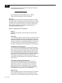
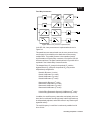
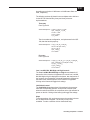
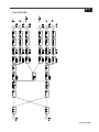
Rear Panel Features (see Figure 2-2)
Figure 2-2 ISP-100 rear panel features.
1. AC Power—Connects to mains via an IEC type AC power cord.
2. RS-232 Port—Links the PC to the unit via a RJ-45 connector.
3. External Sync—Precision frequency reference input to the unit.
4. GPI—Provides a General Purpose Interface for the user. The user
provides inputs to the system via dry or electronic contact
closure inputs. These inputs can be used to change system
settings directly and/or scroll through various settings.
5. Output Slot 5—Accepts either an analog output module or digital
module.
6. Output Slot 4—Accepts either an analog output module or digital
module.
7. Output Slot 3—Accepts either an analog output module or digital
module.
8. Input/Output Slot 2—Accepts an analog input module, analog output
module, or digital module.
9. Input Slot 1—Accepts either an analog input module or digital module.
Power Requirements
The ISP-100 uses a universal switching power supply that accepts input
voltages in the range of 90 VAC to 264 VAC, 50/60 Hz. All countries
using 220/240 VAC except Australia use a ½ amp slow-blow fuse. All
countries using 100/120 VAC and Australia use a 1 amp slow-blow fuse.
Operating Environment
Internal temperature: 50°F to 95°F (10°C to 35°C)
Humidity: 20% to 80%
Rack Mounting
The ISP-100 may be installed in a standard 19-inch (483-mm) equipment
rack with one rack unit (1.75 inches or 44.5 mm) of vertical rack space
per unit.
10 July 1998
2-3
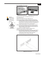
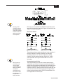
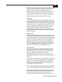
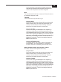
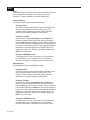
Card Installation Procedure
Figure 2-3 Battery/module tool.
CAUTION:
Failure to observe
anti-static handling
procedures could
result in damage to
equipment.
Figure 2-4 Card being inserted.
1. Ground yourself using a wrist strap and anti-static mat.
2. Turn off the ISP-100.
3. Remove the screws securing the module slot cover.
4. If you are not replacing an existing card please proceed to step 6.
5. Use the battery/module removal tool to remove the existing module.
The battery/module removal tool is attached to the inside of the
front security cover. Place the hook end of the tool into the slot at
the bottom of the module and pull. Place the old module in an
anti-static bag. See Figure 2-3 for more information.
6. Being careful to avoid scraping the underside of the board, slide the
new module into the bottom slots on the card guides located
inside the opening. Push the module into the unit until you feel
resistance. See Figures 2-4 and 2-5.
7. Firmly push on the module’s faceplate to seat the module.
8. Replace the screws that were removed in step 3.
9. Turn on the ISP-100 and verify that the slot indicator for the module is
either solid green or blinking green. If the slot indicator is not
solid green or blinking green, then there is a problem with the
current hardware and/or software. Please refer to the
Troubleshooting section to identify the problem.
Figure 2-5 Card insert detail.
Setup & Installation
2-4
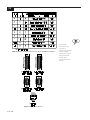
Cable Diagrams
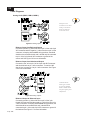
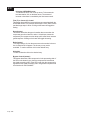
Analog Audio (MIM-1, MIM-2, MOM-1)
Using low-cost
connectors can save
money in the short
term, but failures
could cost more.
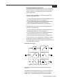
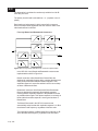
Figure 2-6 Analog inputs.
Balanced Input from Balanced Output
Connect the positive (+) side of the line to pin 2 of the male 3-pin
XLR connector and the negative (-) side of the line to pin 3 of the
connector. In keeping with standard wiring practices, the shield
should not be connected at this end; it should only be connected
to pin 1 of the 3-pin female XLR connector or ground of the
source end. See Figure 2-6 for more information.
Balanced Input from Unbalanced Output
Connect the “hot” wire to pin 2 of the 3-pin male XLR connector
and the shield wire to pin 1 of the connector. To avoid a 6 dB
drop in level, connect pin 3 to pin 1 of the connector. See Figure
2-6 for more information.
Confused about
what type of cable
to use? Try Belden
8451 or 8723. Both
are good quality and
inexpensive.
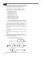
Figure 2-7 Analog outputs.
Balanced Output to Balanced Input
Connect the positive (+) side of the line to pin 2 of the 3-pin
female XLR connector and the negative (-) side of the line to pin
3 of the connector. In keeping with standard wiring practices, the
shield should be connected at this end; it should not be
connected to pin 1 of the male 3-pin XLR connector or ground of
the load end. See Figure 2-7 for more information.
10 July 1998
2-5
Balanced Output to Unbalanced Input
Connect the “hot” wire to pin 2 of the 3-pin female XLR
connector and the shield wire to pin 1 of the connector. To avoid
a 6 dB drop in level, connect pin 3 to pin 1 of the connector. See
Figure 2-7 for more information.
Digital Audio (MDM-1 Cards)
Use the white block
on the I/O module
panels to write a
reference number or
other designator on
by using a permanent
marker. Then make
identical labels for
the cables that plug
into the module.
Figure 2-8 AES/EBU inputs.
AES/EBU Input
Connect the positive (+) side of the line to pin 2 of the male 3-pin
XLR connector and the negative (-) side of the line to pin 3 of the
connector. In keeping with standard wiring practices, the shield
should not be connected at this end; it should only be connected
to pin 1 of the 3-pin female XLR connector or ground of the
source end. The cable used should be 110Ω AES/EBU
compliant cable such as MOGAMI 3080. See Figure 2-8 for
more information.
SPDIF Input
Long unbalanced
cable runs (analog
or digital) are not
recommended.
Figure 2-9 SPDIF inputs.
Connect the positive (+) side of the line to pin 2 of the male 3-pin
XLR connector and the shield of the cable to pins 1 and 3.
Connect a ¼ watt 237Ω 1% resistor between pins 1 and 2 of the
3-pin male XLR connector. Connect the positive (+) side of the
line to the center pin of the RCA connector on the opposite end
of the cable. Connect the shield to the shield of the RCA
connector on the opposite end of the cable. The cable used
should be RG-59 or other similar 75Ω cable. See Figure 2-9 or
the application note MDM-1 SPDIF COMPATABILITY
P/N 42-02-053086 for more information.
Setup & Installation
2-6
AES/EBU Output
Figure 2-10 AES/EBU output.
Connect the positive (+) side of the line to pin 2 of the 3-pin
female XLR connector and the negative (-) side of the line to pin
3 of the connector. In keeping with standard wiring practices, the
shield should be connected at this end; it should not be
connected to pin 1 of the male 3-pin XLR connector or ground of
the receiving end. The cable used should be 110Ω AES/EBU
compliant cable such as MOGAMI 3080. See Figure 2-10 for
more information.
SPDIF Output
The ISP-100 is not capable of providing SPDIF outputs.
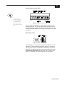
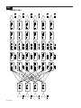
Serial Communications
Serial communications with the ISP-100 can be accomplished either
through the DB-9 connector located under the front panel security
cover or through the RJ-45 connector located on the rear panel. The
computer connected to the ISP-100 must have a free COM port
(1-4). Communications with the ISP-100 will not work properly if the
COM port is shared with another device such as a TEF™ analyzer. It
is important to set the serial port selection switch located under the
front panel security cover to the serial port used. The cable used
should be of low capacitance and suited to data communications.
Front Panel RS-232
Figure 2-11 DB-9 to DB-25.
Figure 2-12 DB-9 to DB-9.
The serial port selector switch should be set in the down
position. If the PC’s COM port is a DB-25 connector, wire the
cable according to Figure 2-11. If the PC’s COM port is a DB-9
connector, wire the cable according to Figure 2-12. A snap-on
10 July 1998
When tuning the
system with a
computer controled
analyzer use a
separate computer
for the analyzer.
Using two PCs will
save time.
2-7
Figure 2-13 RFI choke data.
Not using an RFI
choke while using the
front panel serial port
could cause increased
interference with other
devices and void the
FCC compliance.
RFI choke such as Steward PN: 28B2025-0A0 should be used
at the ISP-100 end of the cable. See Figures 2-13 and 2-16, and
Table 2-1 for more information.
Rear Panel RS-232
Figure 2-14 RJ-45 to DB-25.
Figure 2-15 RJ-45 to DB-9.
The serial port selector switch should be set in the up position. If
the PC’s COM port is a DB-25 connector, wire the cable
according to Figure 2-14. If the PC’s COM port is a DB-9
connector, wire the cable according to Figure 2-15. No RFI
choke is needed. See Figure 2-16 and Table 2-1 for more
information.
RS-232 cable runs
over 50 feet could
cause unreliable
communications. It is
better to use RS-485
converters for
connections over 50
feet. Be sure to read
the application note on
this topic before
buying converters.
Connections Over 50 Feet
The EIA specifications for RS-232 communications allow for
connections up to 50 feet. For longer connections, the RS-232
signals must be converted to a standard, such as RS-485, that is
tolerant of long distances. The converter on the PC end of the
connection can be PC powered, but the converter at the ISP-100
end of the connection must have its own power supply. Before
buying converters please contact TELEX Communications, Inc.
for an application note on this topic.
Setup & Installation
2-8
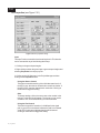
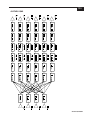
Table 2-1 RS-232 signal pinouts for RJ-45, DB-9, and DB-25 connectors.
Figure 2-16 Connector pinouts.
10 July 1998
The RS-232
standard is very
common to
computer controlled
devices. Table 2-1
and Figure 2-16 can
help you decipher
the RS-232
interfaces of many
devices.
2-9
General Purpose Inputs (GPI)
If a permanent
contact closure is
used, the ISP-100
will remember the
QuickSET selected
even if the AC power
fails.
Figure 2-17 GPI connector pinout.
Dry (i.e. switch) or electronic (i.e. open collector) contact closure
should be sufficient. The closure can be either momentary (10 ms
minimum duration) or continuous. Connect the desired input (1-8)
through the contact closure to common (9). See Figure 2-17 for more
information.
Master Sync Input
Figure 2-18 BNC cable example.
Synchronizing to an external clock source requires RG-58 or other
suitable 50Ω cable terminated with a BNC connector. A precision
(±5 ppm) clock source of 12.288 MHz, 6.144MHz, or 3.072 MHz is
supported. The Master Clock Input must be set to external from the
Properties for Merlin ISP-100 panel in the VUE-IT software. See
Figure 2-18 and page 7-6 of this manual for more information.
Setup & Installation
2-10
THIS PAGE LEFT BLANK
INTENTIONALLY
10 July 1998
3-1
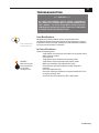
TROUBLESHOOTING
> > > CAUTION < < <
NO USER SERVICEABLE PARTS INSIDE. HAZARDOUS
VOLTAGES AND CURRENTS MAY BE ENCOUNTERED WITHIN
THE CHASSIS. TO AVOID ELECTRICAL SHOCK DO NOT
PERFORM ANY SERVICING OTHER THAN THAT CONTAINED
IN THESE OPERATING INSTRUCTIONS.
User Modifications
User modifications
void the warranty.
Modifications to Merlin products are not recommended. Such
modifications shall be at the sole expense of the person(s) or company
responsible, and any damage resulting from said modifications shall not
be covered under warranty or otherwise.
In Case of Problems
WARNING:
Make sure the power
is disconnected from
the unit before
checking the fuse.
Check the following items:
Verify that the unit is properly connected to an AC power source
and the source is active.
Check the fuse.
Verify that the input connections are properly made.
Verify that the output connections are properly made.
Make sure the output relay indicators are green.
Check the input and output cables for proper wiring and
continuity.
Check the signal source(s).
Check the connection between the computer and the ISP-100 if
a computer is being used.
Check the GPI connections if the GPI is being used.
Troubleshooting
3-2
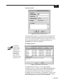
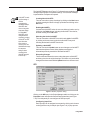
Diagnostics
Table 3-1 LED diagnostic messages.
The ISP-100 was designed with built-in diagnostics that activate when
power is applied to the unit. During the power-up cycle, the ISP-100
performs several self-checks. The ISP-100 also will report problems, as
they happen, while the unit is running. The diagnostic messages are
communicated through the front panel LEDs. Refer to Table 3-1 for a list
of common LED conditions and corresponding diagnostic messages.
Factory Default Mode
A yellow host LED indicates factory default mode. This mode usually
results from either an OS update or memory erasure. When in this
mode a default QuickMAP and QuickSET are loaded that prevents the
unit from passing damaging signals. The QuickMAP configures the
ISP-100 as a straight through processor with high pass filters on the
outputs. The corner frequencies of the high pass filters are set to
20 kHz.
To enter factory default mode, hold in the default switch (see Figure
2-1, item 6) while turning on the power. Continue to hold in the switch
until the front panel LEDs turn red and begin to rotate.
10 July 1998
Note that when the
factory default
QuickMAP is loaded
one or more slot
LEDs may blink
yellow. This is normal
operation and not
an error.
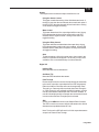
3-3
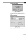
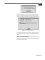
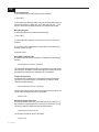
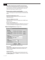
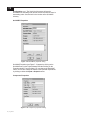
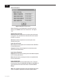
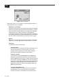
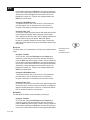
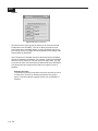
Retrieving Version Numbers
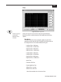
Figure 3-1 About VUE-IT dialog
Application, OS, and DSP version numbers can be obtained by clicking
on the Help menu and then selecting the About entry. See Figure 3-1. If
an ISP-100 is not online, only the application version number will be
reported.
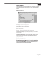
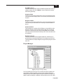
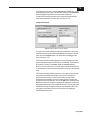
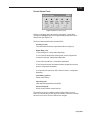
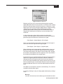
Retrieving Serial Numbers
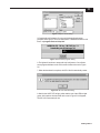
Figure 3-2 Properties dialog.
Clicking on the star icon in the Project Manager and then clicking on the
Properties button will reveal the ISP-100’s serial number. See Figure
3-2.
Troubleshooting
3-4
Changing the Fuse
The universal switching power supply in the ISP-100 adapts to input
voltages from 90 to 264 VAC, 50/60 Hz. To reduce risk of fire, replace
only with same type fuse. The fuse holder is located under the security
cover on the front panel.
WARNING:
Disconnect AC power
before changing the
fuse. Failure to do so
could result in a shock
hazard.
The fuse is a standard 20mm X 5mm European type. The values used
are as follows:
All countries using 220/240 VAC, except Australia, use a ½ A slow-blow
fuse.
Schurter P/N: 0001.2501
Telex P/N: 51-04-052488
WARNING:
Failure to install the
proper fuse could
result in damage to the
unit, property, and loss
of life.
All countries using 100/120 VAC and Australia use a 1 A slow-blow fuse.
Schurter P/N: 0001.2504
Telex P/N: 51-04-051487
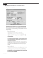
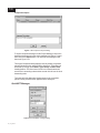
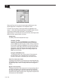
Changing the Battery
Figure 3-3 Battery/module removal tool.
The memory backup battery located under the security cover on the front
panel has an expected life of four years. If the Host LED is blinking the
battery needs to be changed.
CAUTION: The battery used in this device may present a risk of fire or
chemical burn if mistreated. Do not recharge, disassemble, heat above
212°F (100°C) or incinerate. Replace battery with Renata CR2450N or
MERLIN 40-02-052055 only. Use of another battery may present a risk of
fire or explosion.
Be sure to change the battery with the unit on. If the unit is turned off, all
of the setup information stored in the ISP-100 will be lost (i.e. the unit will
return to factory default mode).
10 July 1998
Leave the AC power
connected and the
ISP-100 turned on
when changing a
failed battery.
Failure to do so will
result in loss of
data.
3-5
Saving the ISP-100
configuration data
to disk will guard
against the loss of
data in the event AC
power fails before a
failed battery has
been changed.
Caution: Use only the tool attached to the inside of the security cover to
change the battery. The tool is black anodized so it will not short out the
battery or anything else. DO NOT under any circumstance use pliers to
grip the battery. Doing so could cause damage. See Figure 3-3.
Replace the battery with a Renata CR2450N battery. Replacement
battery/module removal tools as well as replacement batteries are
available from Telex. Their part numbers are:
Battery/Module Removal Tool
Replacement Battery
40-04-052619
40-02-052055
Dispose of used battery promptly. Keep away from children. Do not
disassemble and do not dispose of in fire.
Denmark
Advarsel!
Lithiumbatteri. Eksplosionsfare ved feijlagtig handtering.
af samme fabrikat og type.
Lever det brugte batteri tilbage till leverandoren.
FINLAND
VAROITUS: Paristo voi rajahtaa, jos se on virheellisesti
asennettu. Vaihda paristo ainoastaan valmistajan
suosittelemaan tyyppun. Havita kaytetty paristo valmistajan
ohjeiden mukaisesti.
VARNING: Explosionsfara vid felaktigt batteribyte. Anvand
samma batterityp eller en eller en ekvivalent typ som
rekommenderas av tillverkaren. Kassera anvant batteri enligt
fabrikantens instruktion.
SWEDEN
VARNING:
Felaktigt batteribyte kan medfora fara for explosion. Anvand
darfor endast samma typ eller likvardig typ enligt
apparattillverkarens rekommendation.
Kassera forbrukade batterier enligt tillverkarens anvisning.
Troubleshooting
3-6
Technical Support
Technical questions should be directed to:
Customer Service Department - Merlin
Telex Communications, Inc.
9600 Aldrich Avenue South
Minneapolis, MN 55420 U.S.A.
Telephone: (612) 884-4051
Fax: (612) 884-0043
Helpful Information
Be prepared to provide the following information (if possible):
1.
2.
3.
4.
5.
6.
7.
8.
A detailed description of the problem.
QuickMAP being used.
Serial Number(s)
Version numbers for application, OS, and DSP software.
Front panel LED information.
PC operating system used.
COM port used.
PC type and amount of memory installed.
Procedure for Returns
If a repair is necessary, contact the dealer where this unit was
purchased.
If repair through the dealer is not possible, obtain a RETURN
AUTHORIZATION from:
Customer Service Department
Telex Communications, Inc.
Telephone: 1-800-828-6107 or (612) 884-4051
Fax: 1-800-323-0498 or (612) 884-0043
DO NOT RETURN ANY EQUIPMENT DIRECTLY TO THE FACTORY
WITHOUT FIRST OBTAINING A RETURN AUTHORIZATION.
Be prepared to provide the company name, address, phone number, a
person to contact regarding the repair, the type and quantity of
equipment, a description of the problem and the serial number(s).
10 July 1998
3-7
Save the box the
ISP-100 was
shipped in. It makes
a convenient way to
package a repair
unit.
Shipping to Manufacturer for Repair or Adjustment
All shipments of Merlin products should be made via United Parcel
Service or the best available shipper prepaid. The equipment should be
shipped in the original packing carton; if that is not available, use any
suitable container that is rigid and of adequate size. If a substitute
container is used, the equipment should be wrapped in paper and
surrounded with at least four inches of excelsior or similar shockabsorbing material. All shipments must be sent to the following address
and must include the Return Authorization.
Factory Service department
Telex Communications, Inc.
West 1st Street
Blue Earth, MN 56013 U.S.A.
Upon completion of any repair the equipment will be returned via United
Parcel Service or specified shipper collect.
Troubleshooting
3-8
THIS PAGE LEFT BLANK
INTENTIONALLY
10 July 1998
4-1
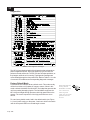
SPECIFICATIONS
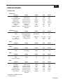
Components
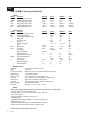
Compressor
Property
Bypass
Threshold
Compression Ratio
Attack Time
Release Time
Detection Window
Crest Factor
Knee
Sidechain Channel
Range
in/out
-60 dB to 0 dB
1.2:1 to 24:1
20 msec to 50 ms
20 msec to 5 sec
20 msec to 5 sec
0.00 to 1.00
hard/soft
self, max of both, or
sidechain
Default
out
0 dB
1.2:1
20 msec
5000 ms
50 ms
.70
hard
depends
Fine
n/a
.5 dB
n/a
.02 ms
1 ms
1 ms
.01
n/a
n/a
Coarse
n/a
3 dB
n/a
1 ms
100 ms
100 ms
.05
n/a
n/a
Range
6,12,18,24
Bessel, Butterworth,
or Linkwitz-Riley
20 Hz to 20 kHz
+0 dB to -96 dB
+/-
Default
12
Butterworth
Fine
n/a
n/a
Coarse
n/a
n/a
Depends
0 dB
+
1/12 Oct.
0.5 dB
n/a
1/3 Oct.
1 dB
n/a
Property
Delay
Range
0 ms to 2.7 s
Default
0 ms
Fine
.02 ms
Coarse
1 ms
Property
Bypass
Level
Range
in/out
16 to 24 bits
Default
out
20 bits
Fine
n/a
1 bit
Coarse
n/a
1 bit
Property
Input Gain
Mute
Absolute Polarity
Range
+18 dB to -96 dB
on/off
+/-
Default
0 dB
off
+
Fine
0.5 dB
n/a
n/a
Coarse
1 dB
n/a
n/a
Property
Bypass
Threshold
Attenuation
Attack Time
Release Time
Detection Window
Key Channel
Range
in/out
-60 dB to 0 dB
0d B to -100 dB
20 msec to 50 ms
20 msec to 5 sec
20 msec to 5 sec
self, max of both, or
sidechain
Default
out
-60 dB
0 dB
.02
5000 ms
50 ms
depends
Fine
n/a
.5 dB
.5 dB
.02 ms
1 ms
1 ms
n/a
Coarse
n/a
3 dB
3 dB
1 ms
100 ms
100 ms
n/a
Crossover
Property
Slope
Class
Cutoff Frequency
Gain
Absolute Polarity
Delay*
Dither
Gain**
Gate
* Depends on QuickMAP selected.
** In digital domain.
Specifications
4-2
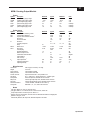
Limiter
Property
Bypass
Threshold
Attack Time
Release Time
Detection Window
Crest Factor
Knee
Sidechain Channel
Range
in/out
-60 dB to 0 dB
20 msec to 50 ms
20 msec to 5 sec
20 msec to 5 sec
0.00 to 1.00
hard/soft
self, max of both, or
sidechain
Default
out
0 dB
.02 ms
5000 ms
50 ms
.70
hard
depends
Fine
n/a
.5 dB
.02 ms
1 ms
1 ms
.01
n/a
n/a
Coarse
n/a
3 dB
1 ms
100 ms
100 ms
.05
n/a
n/a
Range
in/out
+/+12 dB to -12 dB
Default
out
+
0 dB
Fine
n/a
n/a
.1 dB
Coarse
n/a
n/a
1 dB
Range
6,12
20 Hz to 20 kHz
Bessel, Butterworth,
or Linkwitz-Riley
Default
12
20
Butterworth
Fine
n/a
1/12 Oct.
n/a
Coarse
n/a
1/3 Oct.
n/a
Range
6,12
20 Hz to 20 kHz
Bessel, Butterworth,
or Linkwitz-Riley
Default
12
20
Butterworth
Fine
n/a
1/12 Oct.
n/a
Coarse
n/a
1/3 Oct.
n/a
AllPass Filter
Property
Cutoff Frequency
Filter Order
Range
20 Hz to 20 kHz
1,2
Default
20
2
Fine
1/12 Oct.
n/a
Coarse
1/3 Oct.
n/a
LowShelf Filter
Property
Slope
Cutoff Frequency
Boost/Cut
Range
6,12
20 Hz to 20k Hz
+12 dB to -12 dB
Default
12
20
0 dB
Fine
n/a
1/12 Oct.
.1 dB
Coarse
n/a
1/3 Oct.
1 dB
HighShelf Filter
Property
Slope
Cutoff Frequency
Boost/Cut
Range
6,12
20 Hz to 20 kHz
+12 dB to -12 dB
Default
12
20
0 dB
Fine
n/a
1/12 Oct.
.1 dB
Coarse
n/a
1/3 Oct.
1 dB
Notch Filter
Property
Center Frequency
Cut
Bandwidth
Range
20 Hz to 20 kHz
0 dB to -50dB
.08 to 1.0 octaves
Default
20
0 dB
1.0
Fine
1/12 Oct.
1 dB
.01 Oct.
Coarse
1/3 Oct.
6 dB
.1 Oct.
Filters
Property
Bypass
Absolute Polarity
Gain Trim
LowPass Filter
Property
Slope
Cutoff Frequency
Class
HighPass Filter
Property
Slope
Cutoff Frequency
Class
10 July 1998
4-3
PEQ
Property
Center Frequency
Boost/Cut
Bandwidth
Range
20 Hz to 20 kHz
+12 dB to -12 dB
0.08 to 3.0 octaves
Default
20
0 dB
1.0
Fine
1/12 Oct.
.1 dB
1/12 Oct.
Coarse
1/3 Oct.
1 dB
1/3 Oct.
Range
+0 dB to -96 dB
+/+0 dB to -96 dB
+/-
Default
0 dB
+
0 dB
+
Fine
.5 dB
n/a
.5 dB
n/a
Coarse
1 dB
n/a
1 dB
n/a
Property
Left Gain (A)
Right Gain (B)
Left Pad (A)
Right Pad (B)
Range
0,2,4,8 dB
0,2,4,8 dB
-20 dB
-20 dB
Default
0 dB
0 dB
Off
Off
Fine
n/a
n/a
n/a
n/a
Coarse
n/a
n/a
n/a
n/a
Property
Left Gain (A)
Right Gain (B)
Left Mute (A)
Right Mute (B)
Relay Mute
Range
-8,-6,-4,0,8 dB
-8,-6,-4,0,8 dB
on/off
on/off
on/off
Default
0 dB
0 dB
off
off
Fine
n/a
n/a
n/a
n/a
Coarse
n/a
n/a
n/a
n/a
Combine
Property
Channel “1” Entry Gain
Channel “1” Entry Polarity
Channel “2” Entry Gain
Channel “2” Entry Polarity
Input
Output
ISP-100 Component Plots
Compressor
Limiter
AP is a trademark of AudioPrecision, Inc.
Specifications
4-4
Gate
Linkwitz-Riley 3-way Crossover
Notch Filter
Parametric Equalizer Filter
Peaked HighPass Filter
Shelving Filter
AP is a trademark of Audio Precision, Inc.
10 July 1998
4-5
System Measurements
System Frequency Response
System Noise Floor
System THD+N
AP is a trademark of Audio Precision, Inc.
Specifications
4-6
MIM-1 & MIM-2* Analog Input Modules
Power
Symbol
VA18P
VA18M
VD5P
IA18P
IA18M
ID5P
Description
positive analog supply voltage
negative analog supply voltage
positive digital supply voltage
positive analog supply current
negative analog supply current
positive digital supply current
Minimum
17.50
-17.50
4.75
77(43.7)
72(41.6)
113(114)
Typical
18.00
-18.00
5.00
81(46.0)
76(43.75)
123(124)
Maximum
20.00
-20.00
5.50
85(48.3)
80(46.0)
133(134)
Units
volts
volts
volts
milliamps
milliamps
milliamps
Minimum
Typical
0.003(0.002)
0.004
0.003
110
-100
20(24)
+0.01, - 0.1
Maximum
0.007(0.006)
0.007
0.006
107
-80
12.288
48.000
64X(128X)
12.292
48.02
Units
%
%
%
dBu
dB
bits
dB
WST
MHz
kHz
30
0.5
52
±0.05
12000
75
50
32
1.0
40
±0.25
13500
100
80
dB
dBu
degrees
dB
dB
ohms
°F
%
Performance
Symbol
THD+N
IMD
DIM
N
MCLK+
WST+
CMRR
Z
in
Description
Total Harmonic Distortion + Noise
1 Intermodulation Distortion
2 Dynamic Intermodulation Distortion
3 Noise Floor
Channel Crosstalk
Resolution
Frequency Response
4 Delay
Master Clock
Word Clock
Oversampling
Stopband Attenuation
5 Maximum Input Level
6 Interchannel Phase Deviation
Common Mode Rejection
7 Gain Accuracy
8 Input Impedance
Operating Temperature
Operating Humidity
18 (38.7)
12.283
47.98
100(110)
26
11000
50
20
+.02, -0.15
Miscellaneous
9 Overall Size:
Weight:
Synchronous Sampling:
Input connector:
Mating connector:
Internal connector:
XLR pinout:
Serial Interface:
Clock Mode:
Digital Power Down:
Analog Gain:
8.40 long by 2.55 wide by 1.50 high
4.0 ounces
Multiple cards can be synchronized via DPD signal on connector
3 Pin standard female XLR
3 Pin standard male XLR
48 pin standard female F size per DIN 41 612
Pin 1 shield, Pin 2 positive signal, Pin 3 negative signal
Master or slave, selectable via SPI control I/F.
256 or 384 times sample rate, selectable via SPI control I/F.
Selectable via SPI control I/F.
Selectable: 0, -20, -18, -16, -12, 2, 4, 8 dB.
Notes
(Unless otherwise specified measurements are at unity gain with +16 dBu signal.
1
Unity gain, SMPTE 4:1, 60 Hz & 7 kHz sine waves.
Unity gain, DIM30 4:1, 3.15 kHz SQ wave & 15 kHz sine wave, 30 kHz LPF.
3
Power spectral density.
4
Group Delay inherent in conversion process. WST=1/48 kHz
5
20 dB pad engaged.
6
Maximum levels are differential and balanced. Limit set by protection circuit.
7
Relative to unity gain, 1 kHz.
8
Electronically balanced, RF surpressed, differential impedance 20- 20kHz.
9
Maximum dimensions: dominated by panel size for height and width.
2
* MIM-2 differences parenthetically noted.
10 July 1998
4-7
MOM-1 Analog Output Module
Power
Symbol
VA18P
VA18M
VD5P
IA18P
IA18M
ID5P
Description
positive analog supply voltage
negative analog supply voltage
positive digital supply voltage
positive analog supply current
negative analog supply current
positive digital supply current
Minimum
17.50
-17.50
4.75
92
47
114
Typical
18.00
-18.00
5.00
96
51
124
Maximum
20.00
-20.00
5.50
100
55
134
Units
volts
volts
volts
milliamps
milliamps
milliamps
Minimum
Typical
0.003
0.004
0.003
110
-100
20
+0.1, - 0.5
Maximum
0.007
0.007
0.006
107
-80
12.288
48.000
128X
12.292
48.02
Units
%
%
%
dBu
dB
bits
dB
WST
MHz
kHz
Performance
Symbol
THD+N
IMD
DIM
N
MCLK+
WST+
Z
out
Description
Total Harmonic Distortion + Noise
1 Intermodulation Distortion
2 Dynamic Intermodulation Distortion
Noise Floor
Channel Crosstalk
Resolution
Frequency Response
3 Delay
Master Clock
Word Clock
Oversampling
Stopband Attenuation
4 Maximum Output Level
Interchannel Phase Deviation
Output Balance
5 Gain Accuracy
6 Output Impedance
Operating Temperature
Operating Humidity
25
12.283
47.98
75
21
594
50
20
26
0.5
0.5
±0.05
600
75
50
+.2, -1.0
1.0
±0.25
606
100
80
dB
dBu
degrees
dB
dB
ohms
°F
%
Miscellaneous
Overall Size:
Weight:
Input connector:
Mating connector:
Internal connector:
XLR pinout:
De-emphasis:
Relay mute:
DAC mute:
Serial Data Interface:
Analog Gain:
1
8.40 long by 2.55 wide by 1.50 high
4.3 ounces
3 Pin standard male XLR
3 Pin standard female XLR
48 pin standard female F size per DIN 41 612
Pin 1 shield, Pin 2 positive signal, Pin 3 negative signal
48 kHz de-emphasis, selectable via SPI control I/F.
Left and right output relay mute, selectable via SPI control I/F.
Left and right individually or group selectable via SPI control I/F.
7 formats available, selectable via SPI control I/F.
7 Selectable: 0, -8, -6, -4, 8 dB via SPI control I/F.
Notes
Unity gain, SMPTE 4:1, 60 Hz & 7 kHz sine waves.
2
Unity gain, DIM30 4:1, 3.15 kHz SQ wave & 15 kHz sine wave, 30 kHz LPF.
3
Group Delay inherent in conversion process. WST=1/48 kHz
4
Minimum levels are single ended, maximum levels are differential and balanced. Bridging load.
5
Relative to unity gain, 1 kHz.
6
Electronically balanced, RF surpressed, differential impedance 20- 20kHz.
Specifications
4-8
MDM-1 AES/EBU Digital I/O Module
Power
Symbol
VA18P
VA18M
VD5P
IA18P
IA18M
ID5P
Description
Pos Analog Supply Voltage
Neg Analog Supply Voltage
Pos Digital Supply Voltage
Pos Analog Supply Current
Neg Analog Supply Current
Pos Digital Supply Current
Minimum
17.50
Maximum
20.00
122
Typical
18.00
Not Used
5.00
9
Not Used
155
168
Units
Volts
Volts
Volts
mA
mA
mA
Minimum
32
Typical
48
Maximum
>54
Units
kHz
0.00002
0.00016
%
TBD
%
415
pS
90
nS
20
24
+/-0.01
120
bits
bits
dB
dB
dBFS
WST+
periods
Degrees
6.667
TBD
MHz
MHz
Hz
Hz
Hz
Hz
4.75
8
5.50
10
Performance
(Sample Rate Converter Engaged)1
Symbol
F
s
THD+N
IMD
Description
Sample Rate for Digital
2 Input Data
Total Harmonic Distortion
3 plus Noise (RELATIVE)
4 Intermodulation Distortion
(SMPTE 4:1)
5 Jitter in Output Clock
(700 Hz - 100KhZ)
Tolerable Jitter in Input
6 Clock before Loss of Lock
7 Resolution (input)
8
Resolution (output)
9
Frequency Response
10 Dynamic Range
11
Noise Floor
12 Delay through transmitter
4
24
117
-117
43/
64
13 MCLK/2
MCLK+
WSR+
WST+
SCKR+
SCKT+
10 July 1998
24
Interchannel Phase Deviation
Sample Rate Converter
14 Reference Clock Source
Master Clock
15 Receive Word Clock
16 Transmit Word Clock
17 Receive Bit Clock
18 Transmit Bit Clock
0
4.333
TBD
6.144
12.288
(MCLK+)/256
(MCLK+)/256
(MCLK+)/4
(MCLK+)/4
4-9
Performance
(Sample Rate Converter bypassed)
Symbol
F
s
THD+N
IMD
Description
Sample Rate for Digital
19 Input Data
Total Harmonic Distortion
20 plus Noise (RELATIVE)
21 Intermodulation Distortion
(SMPTE 4:1)
Jitter in Output Clock
Tolerable Jitter in Input
22 Clock before Loss of Lock
Resolution (input)
Resolution (output)
23 Frequency Response
24 Dynamic Range
25 Noise Floor
26 MCLK+
WSR+
WST+
SCKR+
SCKT+
Z
in
Z
out
Delay through receiver
27 Delay through transmitter
28 Interchannel Phase Deviation
29 Master Clock
30 Receive Word Clock
31 Transmit Word Clock
32 Receive Bit Clock
33 Transmit Bit Clock
Input Impedance
Output Impedance
Minimum
TBD
Typical
48
Maximum
96
Units
kHz
0.00002
%
0
%
415
35
24
24
24
Equal to Dynamic Range
of input signal
Equal to Noise Floor
of input signal
2
43/
64
TBD
12.288
(MCLK+)/256
(MCLK+)/256
(MCLK+)/4
(MCLK+)/4
110
110
pS
nS
24
24
+/-0
bits
bits
dB
dB
dB
0
24.576
WSR+periods
WST+periods
Degrees
MHz
Hz
Hz
Hz
Hz
Ohms
Ohms
Miscellaneous
Overall Size:
Weight:
Input Connector:
Output Connector:
XLR pinout:
Input Data Format:
Output Data Format:
De-emphasis:
Mutes:
Serial Data Interface:
Synchronous Sampling:
Unless otherwise noted:
8.40" long by 2.55" wide by 1.50" high
3.8 Ounces
3 Pin standard female XLR
3 Pin standard male XLR
Pin 1 shield, Pin 2 positive input, Pin 3 negative input.
AES/EBU (AES3) Professional and S/PDIF. (IEC958) Consumer data formats are automatically identified and
correctly decoded.
AES/EBU Professional, regardless of input data format.
Not implemented; emphasis information from Channel Status Bits is relayed to host via Serial Peripheral
Interface (SPI).
Linked Left and Right input mute selectable via SPI control; linked Left and Right output mute selectable via
SPI control.
TBD
Multiple outputs may be synchronized via DPDB signal on connector. MDM-1 transmitter is slaved to MCLK+,
WST+, and SCKT+ signals. MDM-1 receiver may be configured as Master, to generate MCLK+ (via AES_CLK),
WSR+, and SCKR+ signals derived from input data stream, or as Slave, to receive WSR+ and SCKR+ signals
from card-edge connector, either with or without the Sample Rate Converter. With sample rate converter
engaged, the MDM-1 cannot be configured as the master.
Signal measurements are at unity gain, +16 dBu and 20 Hz to 20 kHz bandwidth.
Power measurements are quiescent.
Operating temperature with non condensing humidity
Specifications
4-10
1
Notes
Per Analog Devices AD1890 data sheet, where applicable.
2
With 6.144 MHz MCLK/2 input.
3
20 Hz to 20 kHz, full-scale input, through sample rate converter, to output via passthrough.
4
From input, through sample rate converter, to output via passthrough.
5
When installed in ISP-100.
6
When installed in ISP-100.
7
Input samples longer than 20 bits are truncated to 20 bits.
8
Least four significant bits are zero filled.
9
DC to 20 kHz input, through sample rate converter, to output via passthrough.
10
20 Hz to 20 kHz, -60 dB input, through sample rate converter, to output via passthrough.
11
From input, through sample rate converter, to output via passthrough.
12
From SDO0 pin on card connector, through transmitter, to output. The fractional-sample delay is inherent in the Crystal CS8404 transmitter.
13
From input, through sample rate converter, to output via passthrough.
14
Frequency is tripled by a PLL on the MDM-1 before being applied to the sample rate converter.
15
Must be derived from MCLK+.
16
Must be derived from MCLK+.
17
Must be derived from MCLK+.
18
Must be derived from MCLK+.
19
Must be nominally 48 kHz when installed in ISP-100.
20
From input to output via passthrough.
21
From input to output via passthrough.
22
When installed in ISP-100.
23
DC to Fs/2.
24
From input to output via passthrough.
25
From input to output via passthrough.
26
From input, through receiver, to SDI0 pin on card connector.
27
From SDO0 pin on card connector, through transmitter, to output. The fractional-sample delay is inherent in the Crystal CS8404 transmitter.
28
From input to output via passthrough.
29
Must be Fs x 256.
30
Must be derived from MCLK+.
31
Must be derived from MCLK+.
32
Must be derived from MCLK+.
33
Must be derived from MCLK+.
Physical
Height
1.75 inches (44.5 mm)
Width
19.0 inches (483 mm)
Depth
14.5 inches+0.5” (368 mm + 12.7 mm) for protrusions
Weight
Approx.12.9 lbs. (5.9 kg)
Included Accessories
IEC power cord, user’s manual, software, spare fuse
Power
Universal AC input voltage
90-264 VAC; 50-60 Hz; 35 W Maximum
Internal Power Supply Sync. Frequency - 153.6 kHz
10 July 1998
5-1
INSTALLING VUE-IT
Minimum System Requirements
CPU: Pentium® processor.
VUE-IT is currently
not available for
Windows NT.
OS: Microsoft® Windows 3.1x, Windows 95, or Windows 98
Memory: 8MB RAM
Hard Drive: 5MB of available space (beyond swap file needs)
Disk Drive: 3.5 inch high-density
Monitor: 640X480, 256 color
Pointing Device: mouse or other Windows compatible pointing device
Communications: free COM port (1-4) with 16550 UART
Identifying a Serial Port
The ISP-100 requires a serial port to communicate with the PC. You
must determine if you have a free 16550 serial port on the PC you intend
to use with the ISP-100. You can do this by looking at the back of the
computer for an empty 9-pin D-sub male (DB-9) or a 25-pin D-sub male
(DB-25) connector. If you are unable to find an available serial port, then
you must either disconnect a device from one of the ports that is
currently being used, or install an additional serial port.
If you are unfamiliar with this, please contact your local computer dealer
for assistance.
NOTE: It may be necessary to remove device drivers attached to serial
ports in Windows 95. A good example of this would be a device driver
for an external modem. This will eliminate the possibility of a software
conflict between the VUE-IT software and other device drivers.
Loading the Software
Leaving programs
running while trying
to install VUE-IT
could cause
problems.
1. Close all programs before beginning installation.
2. Insert the disk labeled “VUE-IT FOR THE ISP-100” into your 3.5-inch
floppy drive.
3. Windows 95 users should click on the Start button and select Run.
4. Windows 3.1x users should click on File and select Run.
5. Type “A:\setup.exe” (Substitute the appropriate drive letter for your
system.)
6. Click on the OK button and follow the instructions as they appear on
the screen.
7. Reboot the computer.
Installing VUE-IT
5-2
Updating the ISP-100’s Operating System
Figure 5-1 OS mismatch dialog.
Figure 5-2 OS download request dialog.
The updating of the operating system contained in the ISP-100’s flash
memory is usually required after loading a new version of VUE-IT on the
computer. A dialog box such as those in Figures 5-1 and 5-2 usually
indicates this.
The procedure is as follows:
1. Make sure both the computer and the ISP-100 are both turned off.
2. Connect the computer to the ISP-100.
3. Hold in the default switch located to the left of the power switch and turn
on the ISP-100. Continue to hold in the default switch until the LEDs turn
red and begin rotating. See Figure 2-1 item 6.
4. Turn on the computer and start the VUE-IT software. You should see a
dialog box similar to that in Figure 5-2.
10 July 1998
5-3
Figure 5-3 Open OS file dialog.
5. Download the OS software file you need via the application when
prompted. See Figure 5-3 for more information. The default location for OS
files is “c:\program files\vue-it\isp-100”.
Figure 5-4 Download progress dialog.
6. The lights will continue to rotate with only brief pauses. You will also
see a progress indicator on the PC’s screen similar to the one in Figure
5-4.
7. When the download is complete, the ISP-100 will automatically restart.
Figure 5-5 ISP-100 detected dialog.
8. Wait for the HOST LED to light yellow and the rest of the LEDs to light
green. At this point a window similar to the one in Figure 5-5 will appear.
The ISP-100 is now ready for use.
Installing VUE-IT
5-4
Configuring the Software
Turn on the ISP-100. The power switch is located at the far right under the
front access panel. This is accomplished by placing the switch in the
down position. See Figure 2-1 for the location of the power switch.
Check to make sure that the LEDs light in a percentage complete fashion.
Launch the VUE-IT application on the PC.
Figure 5-6 System configuration dialog.
A dialog box similar to the one in the Figure 5-6 should appear.
The System Configuration dialog box (see Figure 5-6) allows the user to
select the serial port used, modify directories used, and enter information
such as the company’s and designer’s names. It is recommended that
you do not change the directory names unless you are an experienced
user and know the implications of doing so. See the entry titled “VUE-IT
File System” in section 6 for more information. After the proper information
has been entered or selected, click on the OK button.
You will not be
prompted again for
this information. You
can change it at any
time by clicking on
the Option menu
and selecting
Configure
Configure.
Figure 5-7 ISP-100 detected dialog.
After clicking on the OK button a dialog box like the one in the Figure 5-7
should appear. Click on the OK button. The ISP-100 and the PC are now
ready for use together.
10 July 1998
5-5
Figure 5-8 ISP-100 not detected dialog.
If a dialog box like the one in Figure 5-8 appears in place of the one in
Figure 5-7, the cable connecting the computer to the ISP-100 should be
checked. If no problem is found there, try selecting a different serial port.
Figure 5-9 Communications error dialog.
If a dialog box similar to the one in the Figure 5-9 appears, then a serial
port that does not exist has been selected. Another serial port must be
selected.
You can change the serial port selection at any time by clicking on the
Option menu and selecting Configure.
If you continue to have problems please contact Technical Support. See
section 3 for contact information.
Installing VUE-IT
5-6
THIS PAGE LEFT BLANK
INTENTIONALLY
10 July 1998
6-1
GETTING STARTED
Starting VUE-IT
Figure 6-1 VUE-IT workspace.
When VUE-IT is started, you will see a screen similar to the one in Figure
6-1. The window displayed in Figure 6-1 is the basic environment in which
all interactions with VUE-IT take place. There are six key features of this
window that users should be aware of:
1. Menu Bar - This is where the user will find features that are either
integral to VUE-IT or standard in windows. When you see a reference to a
command located under a menu, this is where you should look. Below the
menu names are short-cut buttons that provide access to common
commands via a single mouse click. The buttons are (from left to right):
New Project, Open Project, Save Project, Revert, Scan, Project Manager,
Help, and Exit.
2. Work Space - This is where the QuickMAP, Project Manager,
QuickSET Manager, and component boxes appear. This is the main work
area for the user.
3. General Help - This box displays helpful messages about commands
and functions.
4. Component/Parameter Type - This box displays the name of the
component or parameter selected.
5. Component/Parameter Input Range - This box displays the input
value range for a component or parameter.
6. Online/Offline Status - This box displays the status of the connection
between the ISP-100 and the PC running VUE-IT.
Getting Started
6-2
Starting a New Project
Figure 6-2 Create new project dialog.
To start a new project select New Project from the File menu. A panel
similar to the one in Figure 6-2 will appear.
You are allowed to select a name of up to eight characters for the project,
assign a path for the project to be stored, and create a new subdirectory if
needed. You also will need to select the method by which the new project
will be created. To select the method, click on the diamond to the left of
either the Build from Script or Upload from ISP-100 options. The Build
from Script option uses files stored on your hard drive to create the
QuickMAP. The Upload from ISP-100 option creates the QuickMAP
based on the information stored in an ISP-100 that is connected to the
PC. When you have given the project a name, assigned a path or
directory, and selected the creation method, click on the Create button to
start the project creation process.
Figure 6-3 QuickMAP selection dialog.
If the Build from Script option is selected a dialog similar to the one in
Figure 6-3 will appear. Here you will be able to select the script that will be
10 July 1998
6-3
used to create the QuickMAP. The QuickMAPs can be sorted by Name,
I/O Configuration, Creation Time, and Modification Time. To sort the
QuickMAPs, click on the heading button of the property you wish to sort
by (i.e. Name, I/O Configuration, etc.). The first click of the mouse will
sort the QuickMAPs in ascending order and the second click will sort
them in descending order.
If you select the Upload from ISP-100 option there will be a pause while
the QuickMAP in the ISP-100 is loaded. Using the Upload from ISP-100
option is a good way to retrieve the settings of an ISP-100 when the
original project file does not exist. Please note that this feature is NOT
backward compatible. An ISP-100 with a project created using a previous
version of VUE-IT will NOT be able to upload the project to your computer.
Figure 6-4 New project created.
CAUTION:
Trying to connect to an
ISP-100 with a VUE-IT
version different from
the one used to create
the project stored in it is
not allowed. Do not
update the OS.
Updating the OS will
erase the project stored
in the ISP-100. Use the
version of VUE-IT that
created the project to
Upload the project from
the ISP-100 to the PC
and save it. Then
update the OS and
restore the project..
After the QuickMAP has been created three panels will appear on the
screen. They are: Project Manager, QuickSET Manager, and QuickMAP.
See Figure 6-4.
VUE-IT File System
When a new project is created a number of files and directories are
created. By default, the directory structure used by VUE-IT projects is as
follows:
C:\PROGRAM FILES\VUE-IT\ISP-100\PROJECTS\<Directory Name>\<File
Name>.<Extension>
The files created by a new project are stored in the project directory. The
file names are the same as the name given the project when it was
created. The file name formats are as follows:
Project File:
Project QuickMAP File:
Project QuickSET File:
Project GPI Settings:
<File Name>.VUE
<File Name>.QMS
<File Name>.QM0
<File Name>.GP0
Getting Started
6-4
Archiving Projects
To save a project for archival purposes do the following:
1. Exit VUE-IT.
2. Save the project directory and the four files mentioned previously to
the archival media (i.e. floppy disk, zip™ disk, tape, CD, etc...). The
directory name will usually be the name you assigned the project.
Mounting Projects
To install a project from an archive do the following:
1. Exit VUE-IT.
2. Create a directory under the C:\PROGRAMS\VUE-IT\ISP-100\PROJECTS\
directory.
3. Copy the four files mentioned previously above to the new project
directory created in step 2.
4. Restart VUE-IT.
QuickMAP Template Files
QuickMAP template files are, by default, located under the following
directory:
C:\PROGRAM FILES\VUE-IT\ISP-100\QMAPS\
The QuickMAP template file location is important to users who either
have access to QuickMAP creation software or have been sent a new
QuickMAP not contained in a standard VUE-IT installation.
Component Directory
Component files created by the Component Export command and
used by the Component Import command are, by default, located
under the following directory:
C:\PROGRAM FILES\VUE-IT\ISP-100\COMPLIB\
The files have the same name as the one assigned during export. The
format of the component file name is as follows:
<File Name>.CMP
Operating System (OS) Files
OS files are loaded into the ISP-100’s flash memory by VUE-IT. For
the procedure on updating the ISP-100' s OS, see section 5. The OS
files are, by default, located under the following directory:
C:\PROGRAM FILES\VUE-IT\ISP-100\
The format of the OS file name is as follows:
<File Name>.OSI
10 July 1998
7-1
Using VUE-IT
VUE-IT has a variety of commands available to the user. These commands
are accessible via the menu items along the top of the VUE-IT workspace
window.
File (see Figure 7-1)
Figure 7-1 File menu.
New Project - Creates a new project file.
Open Project - Loads an existing project.
Save - Saves a project.
Save as... - Saves an existing project under another name.
Activate Project Manager - Opens the project manager window after it
has been closed.
Activate QuickSET Manager - Opens the QuickSET Manager window
after it has been closed. This function only works when one or more
components are open.
Exit - Shuts the program down.
The last eight projects used are listed at the bottom of the menu if the
Most Recently Used files (MRU) option is checked in the Preferences
panel under the Options Menu. If the project no longer exists you are
asked if you want to remove the item from the list.
Using VUE-IT
7-2
Edit (see Figure 7-2)
Figure 7-2 Edit menu.
Cut - Removes the selected item(s) and places them on the clipboard.
Copy - Places a copy of the selected item(s) on the clipboard.
Paste - Inserts item(s) from the clipboard.
Tools (see Figure 7-3)
Figure 7-3 Tools menu.
Refresh Directories - Updates the directory list for QuickMAP and
component library files.
Scan - Looks to see if an ISP-100 is connected to the computer.
Options (see Figure 7-4)
Figure 7-4 Options menu.
Preferences - Allows the user to setup preferences available within
VUE-IT.
System Configurations - Allows the user to setup project directories,
company name, designer’s name, communications settings, etc.
10 July 1998
7-3
Window (see Figure 7-5)
Figure 7-5 Windows menu.
Cascade - Arranges panels in overlapping layers.
Tile - Arranges panels side-by-side.
Arrange Icons - Arranges minimized panels side-by-side.
Help (see Figure 7-6)
Figure 7-6 Help menu.
About - Lists the current application software version, OS version, and
DSP version if an ISP-100 is connected and online. If an ISP-100 is not
online, only the application software version will be reported.
Preferences (see Figure 7-7)
Figure 7-7 VUE-IT preferences dialog.
Soft Mute Ramp in Ms
This sets the amount (0 ms - 1000 ms) of ramp-up and ramp-down
Using VUE-IT
7-4
there is when changing between QuickSETs or using a GPI mute.
The total time for ramp-up and ramp-down is twice the time specified.
(i.e. If 50 ms of time is specified, the ramp-down will be 50 ms and the
ramp-up will be 50 ms. Thus, the total time between the start of the
ramp-down to the end of the ramp-up is 100 ms.)
Display recently opened files in the File Menu
The check box turns on and off the Most Recently Used files (MRU)
function. Removing the check mark will disable the function and clear
the list.
Open Device Status panel on error
When a device status message is received, the status panel is
automatically opened.
Display QuickMAP pop-up names
If selected the pop-up component nametags in the QuickMAP layout
display are shown.
Display Filter Bandwidth in “Q”
If the box is checked filter bandwidth to be displayed in terms of Q. If it
is unchecked bandwidth will be displayed in terms of octave fraction.
System Configurations (see Figure 7-8)
Figure 7-8 System configuration dialog.
New Projects
This is the directory under which new projects are stored. To modify
the path, click on the Modify... button located to the right of the
directory path entry.
Component Library
This is the directory under which the component presets are stored.
To modify the path, click on the Modify... button located to the right of
the directory path entry.
10 July 1998
7-5
QuickMAP Library
This is the directory under which QuickMAP templates are stored. To
modify the path, click on the Modify... button located to the right of
the directory path entry.
Company Name
This entry is reserved for possible future use in documenting projects.
You can enter the company name, but it currently will not be saved in
a project.
Designer’s Name
This entry is reserved for possible future use in documenting projects.
You can enter your name here, but it currently will not be saved in a
project.
Communications
This list allows you to select which COM port (1-4 and offline) on the
PC will be used for communications with the ISP-100. Once a new
COM port is selected you may need to select Scan from the Tools
menu in order for the software to identify an ISP-100 connected to the
new COM port.
Default Preference
This list is reserved for future program expansion. Via this list you
would be able to change settings based on a designer’s preferences.
This would allow for multiple designers using the same program on the
same PC.
Project Manager
Figure 7-9 Project manager dialog.
The Project Manager (see Figure 7-9) contains information related to the
project design. Via the manager, the user is able to define GPI inputs,
configure inputs and outputs, import and export component settings, and
adjust component settings. In addition to these functions, the user is also
Using VUE-IT
7-6
able to access ISP-100 statistics such as free memory, number of
QuickSETs, etc.
Properties for the ISP-100
Figure 7-10 ISP-100 properties dialog.
Properties for the ISP-100 (see Figure 7-10) reports statistics on the
ISP-100. It is accessed by double clicking on the entry next to the
star icon (see Figure 7-9), or by clicking on the entry next to the star
icon (see Figure 7-9) and then clicking on the Properties button in the
Project Manager.
Master Clock Selection
There are four location selections for master clock:
1. Main Board – no reference frequency. (default).
2. Slot #1 – 12.288 MHz reference frequency (AES/EBU only).
3. Slot #2 – 12.288 MHz reference frequency (AES/EBU only).
4. External Reference – 12.288, 6.144, or 3.072 MHz via
external input BNC.
An error will be returned if either slot 1 or slot 2 is selected as the
clock master while the slot contains a card configured to use the
sample rate converter (SRC).
The default clock master is the main board. If the user places an
AES/EBU card in an input slot the user can manually change the
clock master to select either the main, external sync, or input
card slot.
Input Slot Bit Level
The input slot bit level can be set to either 20-bit or 24-bit. 20-bit is
usually associated with consumer grade (SPDIF) digital audio.
24-bit is usually associated with professional grade (AES/EBU)
digital audio. However, it is possible to have consumer grade 24bit digital audio. For optimal performance be sure to set the proper
bit level for the audio data stream.
10 July 1998
7-7
Project Properties
Figure 7-11 Project properties dialog.
Project properties (see Figure 7-11) provides the user with information
on the name of the project, project location, and notes related to the
project. It is accessed by double clicking on the project name entry, or
by clicking on the project name entry and then clicking on the
Properties button in the Project Manager.
QuickMAP Selection
A QuickMAP is a
signal processing
topology used with
an ISP-100. The
QuickMAP sets the
signal paths and
processing from
input to output. An
ISP-100 can hold one
QuickMAP at a time.
Figure 7-12 QuickMAP selection dialog.
QuickMAP Selection (see Figure 7-12) is where a project’s
QuickMAP is chosen. It appears when the Build From Script option
is selected when setting up a new project. Here you will be able to
select the script that will be used to create the QuickMAP. The
QuickMAPs can be sorted by Name, I/O Configuration, Creation Time,
and Modification Time. To sort the QuickMAPs, click on the heading
button of the property you wish to sort by (i.e. Name, I/O
Using VUE-IT
7-8
Configuration, etc.). The first click of the mouse will sort the
QuickMAPs in ascending order and the second click will sort them in
descending order. See section 6 for the location of the QuickMAP
directory.
QuickMAP Properties
Figure 7-12 QuickMAP properties dialog.
QuickMAP Properties (see Figure 7-13) appear by clicking on the
QuickMAP entry in the Project Manager and then clicking on the
Properties button. From this dialog, you can change the QuickMAP
name. You can also change the names of the input and output labels
by clicking on either the Inputs or Outputs buttons.
Component Properties
Figure 7-14 Component properties dialog.
10 July 1998
7-9
Clicking on a component (i.e. Cut, Compressor, Limiter, etc.) in the
Project Manager (see Figure 7-9) and then clicking on the Properties
button displays the properties for the selected component.
Component Properties allow the user to name the component and
enter notes related to that component. See Figure 7-14.
Component Export
Figure 7-15 Component export dialog.
To export component settings from the Project Manager, click on the
desired component entry in the Project Manager (see figure 7-9) and
then click on the Export button. You will then see a dialog box like
the one in Figure 7-15.
The Export Component dialog displays currently existing component
presets’ filenames in the lower left corner of the dialog. These files can
be sorted by clicking on the Name, Type, and Group heading
buttons. The first mouse click on one of these buttons will sort the list
in ascending order and the second click will sort the list in descending
order.
The Export Component dialog requires you to supply a name for both
the component settings and the group to which it is assigned. In
addition to these entries, you are also allowed to provide a brief
description of the settings. Once the component name, group, and
description have been entered, click on the OK button. Clicking on the
OK button causes the program to create a file holding the component
settings and description in the COMPLIB directory. The full path to the
COMPLIB directory is assigned when you first installed VUE-IT. See
the System Configurations entry for information on changing the
COMPLIB directory’s path.
Using VUE-IT
7-10
Component Import
Figure 7-16 Component import dialog.
To import component settings from the Project Manager, click on the
desired component entry in the project manager (see Figure 7-9) and
then click on the Import button. You will then see a dialog box like
the one in Figure 7-16.
The Import Component dialog displays currently existing component
presets’ filenames in the upper half of the dialog box. These files can
be sorted by clicking on the Name, Type, Group, and Mod Time
heading buttons. The first mouse click on one of these buttons will
sort the list in ascending order and the second click will sort the list in
descending order.
The lower half of the dialog box displays notes on the component
preset currently selected in the upper half of the dialog box.
QuickSET Manager
Figure 7-17 QuickSET manager dialog.
10 July 1998
7-11
The QuickSET Manager (see Figure 7-17) allows the user to develop and
manage multiple groups of component settings. The QuickSET Manager
is opened when a component is opened.
A QuickSET is made
up of the settings of
all of the
components in a
QuickMAP. Multiple
QuickSETs allow
users to change the
component settings
for a QuickMAP.
QuickSETs can be
changed without a
computer by assiging
a QuickSET to a GPI
input. When that
input receives a
contact closure, the
QuickMAP will change
its component
settings to those
contained in the
QuickSET assigned
to the GPI pin.
Creating New QuickSETs
The user can name a group of settings by clicking on the New button
and then entering the name in the pop-up window and clicking on the
OK button.
Deleting QuickSETs
If at least two QuickSETs exist, the user can delete an inactive one by
clicking on the Delete button, selecting the QuickSET from the list,
and then clicking on the OK button.
Selecting the Active QuickSET
The user can select a QuickSET from the list of available QuickSETs
by clicking on the arrow next to the Active QuickSET entry and
selecting the desired QuickSET from the list.
Updating a QuickSET
The user can use the Update button to save changes to a QuickSET
that has already been created. Using Update overwrites the
information previously saved in the selected QuickSET.
Discarding Changes
The Revert button allows the user to make changes to a QuickSET,
and then go back to the original settings. This button only works when
changes have been made and the Update button has not been used.
GPI
Figure 7-18 GPI properties dialog.
Clicking on the GPI entry in the Project Manager and then clicking on the
Properties button will open the General Purpose Interface (see Figure
7-18). From this panel you can configure the GPI input pins.
Configuring Input Pins
Each input pin can be assigned a command by clicking on the button
to the right of the entry for that pin (see Figure 7-18). A pop-up menu
Using VUE-IT
7-12
will appear, and the proper command can be selected from the list by
clicking on it. The list displays the following options:
Empty - No command assigned to input pin.
Mute Combo - The initial contact closure causes the outputs to
mute. The subsequent contact closure causes the output to un-mute.
Mute Enable - Contact closure causes the outputs to mute.
Mute Disable - Contact closure causes the outputs to un-mute.
QuickSET Increment - Contact closure causes the next QuickSET
stored in memory to be loaded into the QuickMAP.
QuickSET Decrement - Contact closure causes the previous
QuickSET stored in memory to be loaded into the QuickMAP.
QuickSET Select - Contact closure causes the specified QuickSET
to be loaded into the QuickMAP.
Testing the GPI Assignments
Figure 7-19 GPI panel.
If you click on the GPI entry and then click on the Design button, you
will see a panel like the one in Figure 7-19. The panel in Figure 7-19
will allow you to simulate GPI contact closures without having to
hookup external contact closures to the GPI inputs of the ISP-100.
10 July 1998
7-13
QuickMAP
A QuickMAP is a
signal processing
topology used with
an ISP-100. The
QuickMAP sets the
signal paths and
processing from
input to output. An
ISP-100 can hold one
QuickMAP at a time.
Figure 7-20 QuickMAP panel.
Double clicking on the QuickMAP (name) entry or by clicking on the entry
and then clicking on the Design button can access a graphical
representation of the selected QuickMAP (see Figure 7-20).
Clicking on the green input triangles in the QuickMAP will open the I/O
Properties dialog (see Figure 7-21).
Clicking on the green output triangles will open the Output Meters (see
Figure 7-24).
Clicking on the component boxes will open the component. Placing the
pointer on a component, holding down the left mouse button, and dragging
the component onto a component of the same type and releasing the
mouse button will copy the component settings from the component being
dragged to the component it is dropped on.
QuickMAP Component Bypassing
Right clicking on the component boxes will produce a pop-up menu. The
user is able to modify component settings (this is the same as left clicking
on the component), access its properties, import or export settings, and in
selected cases bypass the component. A fully bypassed component will
appear red in the QuickMAP. Please note that this only occurs when the
main bypass is activated for that component.
Using VUE-IT
7-14
I/O Properties (see Figure 7-21)
Figure 7-21 I/O properties dialog.
Input
The Input Function controls the levels entering the unit. This function
can be accessed in any of the following three ways:
1. Clicking on the green input triangles.
2. Right clicking on either the green input or green output triangles and
selecting Properties from the pop-up list.
3. Clicking on the I/O Slots entry in the Project Manager and then
clicking on the Properties button.
Using the Stereo Control
This button controls the tracking of the Gain/Attenuator levels. If
the LED is gray, then the two channels do not track each other. If
the LED is blue, then the channels track each other. Clicking on
the button will toggle the setting.
Gain
To change settings, click on the arrow next to the number in the
text box. A selection list will appear. The list may or may not be
scrollable. Click on the desired entry to make a selection.
Using the Pad Control
This button controls the insertion of a -20dB pad in the signal
path. A gray LED on the button indicates the pad is not inserted.
A red LED on the button indicates that the pad is inserted.
Clicking on the button will toggle the setting.
10 July 1998
7-15
Output
The Output function controls the output levels from the unit.
Using the Stereo Control
This button controls the tracking of the Gain/Attenuator levels. If
the LED is gray, then the two channels do not track each other. If
the LED is blue, then the channels will track each other. Clicking
on the button will toggle the setting.
Mute Control
This button determines if the output signal will be muted. A gray
LED indicates that the signal is not muted, while a red LED
indicates that the signal is muted. Clicking on the button will
toggle the setting.
Using the Relay Control
This button activates and deactivates the output relays. A gray
LED indicates that the audio path is not complete. A green LED
indicates that the audio path is complete. Clicking on the button
will toggle the setting.
Gain
To change settings, click on the arrow next to the number in the
text box. A selection list will appear. The list may or may not be
scrollable. Click on the desired entry to make a selection.
Digital I/O
In Mute (RX)
Mutes the AES receiver data stream.
Out Mute (TX)
Mutes the AES transmitter data stream
Pass Through
Routes the input from the receiver directly through the transmitter
to the card’s output (the output data from the DSP is bypassed).
Either the In-Mute or Out-Mute will mute the output when Pass
Through is on. Data may still be received when Pass Through is
on. Pass Through is only valid with a 48 kHz bit stream, or with a
non-48 kHz bit stream and Sample Rate conversion enabled. A
non-48 kHz sample rate with no sample rate conversion will result
in an error when the Pass Through option is selected.
SRC
Clicking on the SRC button turns on the Sample-Rate-Converter.
The SRC is used to convert non-48 kHz data streams into 48 kHz
data streams compatible with the ISP-100.
Note: Turning on the SRC will result in a 20-bit output data stream
except in the case of Pass Through.
Using VUE-IT
7-16
Status Information
Figure 7-22 Digital I/O status panel.
Status information can be obtained for card slots 1 and 2 by
clicking on the Status button in the desired slot. See Figure
7-22.
Sample Rate Converter
On indicates that the sample rate conversion option is selected
on the card. The card cannot be selected as the clock master if
the SRC is turned on.
Off indicates that the sample rate conversion option is not
selected on the card.
Input Stream Format
Pro indicates that the digital receiver has detected an AES-EBU
formatted data stream.
Consumer indicates that the digital receiver has detected an
SPDIF formatted data stream.
Input Stream Emphasis
Emphasis indicates that the sending device has added emphasis
to the incoming data stream.
None indicates that the sending device has not emphasized the
incoming data stream.
Input Sample Rate
Indicates the sample rate of the data stream in kHz. There are
three possible frequencies 48.0 kHz, 44.1 kHz, and 32.0 kHz. All
other frequencies above and below these are listed as Out of
Range.
Note: The emphasis information in the output data stream will be
set to no emphasis, regardless of the input emphasis status.
10 July 1998
7-17
Device Status Panel
Figure 7-23 Device status panel.
Clicking on the entry next to the star icon (see Figure 7-9) and then
clicking on the Design button in the Project Manager opens the Device
Status Panel. See Figure 7-23.
The device status panel has five simulated LEDs:
Clock Sync (red)
The main board cannot lock to specified location or frequency.
Digital Data (red)
1. Data validity error. Card position dependent.
2. A non-48 kHz Sample Rate is being used, and no Sample Rate
Converter is selected. Card position dependent.
3. Non-Audio Input Stream. Card position dependent.
4. Slot Cannot be chosen as master and have sample rate converter
present. Card position dependent.
5. An input slot must have an AES card to be master. Card position
dependent.
Low Battery (yellow)
Please check battery.
Input Clip (red)
Input audio has clipped before the DSPs.
Process Clip (red)
Which slot and channel caused the clip.
The specifics of an error condition can be found by clicking on the ?
button. You are also able to clear the error indication. If the error condition
still exists or reoccurs, the error LED will turn on again.
Using VUE-IT
7-18
Output Meters
Figure 7-24 Output meter panel.
The Output Meters (see Figure 7-24) provide monitoring of the outputs of
the DSPs before digital-to-analog conversion. To activate the Meters, click
on the green output triangles in the QuickMAP, or click on the Meter Bank
entry in the Project Manager and then click on the Design button.
10 July 1998
8-1
PROCESSING COMPONENTS
The components used in the VUE-IT interface have a wide variety of
controls for adjusting settings.
Each component description begins with a full explanation of the
component including all of the parameters that can be adjusted. In some
areas the explanations may go into more depth than the average user
would need. This was done in order to satisfy the advanced user who
feels a need to understand the inner workings of the component.
References to specific journal articles and other supplementary sources
are provided for further reading.
An explanation of how to manipulate the various controls follows the
component explanation. In many instances a specific parameter may
have multiple means of adjustment. An example of this would be the
gain control in the Gain component. A user accustomed to traditional
hardware would probably prefer the virtual faders and knobs, whereas a
user accustomed to computers and exact entries would probably prefer
the text box where the amount of gain or attenuation can be directly
entered.
Processing Components
8-2
Combine
Figure 8-1 2-to-1 combine component.
The Combine component (see Figure 8-1) adds multiple input signals
together and sends the sum to a single output. In QuickMAPs, 2-to-1,
3-to-1, and 4-to-1 combines may exist. The combine’s default attenuation
is set so that the combine’s output level is unity. In every case the
attenuation applied to each input channel may be independently adjusted
between -96 dB and 0 dB, or muted, and the polarity applied to each
input channel may be independently set to + or - (in-phase or out-ofphase). Attenuation and polarity are applied to the input signals before
they are added to the combination.
Bypassing a combine sets all attenuations to 0 dB and all polarities to +
(in-phase).
Input Attenuators
The input attenuators can be adjusted three ways:
Using the Knob
Click on the indicator on the knob and while continuing to hold
down the mouse button, move the mouse in an arc. The
numbers in the box below the knob will change. When the
desired level is reached, release the mouse button.
Using the Text Box
Click in the box. Using the Back Space and/or Delete keys
erases the current entry and enters the new level. Be sure to
press the Enter key after the entry is made. Clicking outside the
text box without pressing the Enter key will cause the setting to
return to the number that it was before a change was attempted.
Alternatively, click and drag across the number in the box to
highlight the number in it. Type the new setting and press the
Enter key when finished.
Using the UP/DOWN Arrows
To increase the level, click on the up arrow. To decrease the
level attenuation, click on the down arrow. The amount of
increase or decrease is controlled by the fine/coarse control.
10 July 1998
8-3
Fine (F) or Coarse (C) Control
This button determines the increment/decrement associated with the
UP/DOWN arrows. Fine produces small steps in value, while Coarse
provides large steps in value. Clicking on the button will toggle the
setting.
Polarity Control (+/-)
This button determines the polarity of the signal. A + indicates that
the signal will not have it’s phase altered. A - indicates that the
signal’s phase will be changed 180°. Clicking on the button will
toggle the setting.
Mute Control (M)
This button determines if the input signal will be muted. A black M
indicates that the signal is not muted, while a red M indicates that the
signal is muted. Clicking on the button will toggle the setting.
Bypass Control (master)
This button determines if the component is in the processing chain. If
the LED on the button is gray, then the component is inserted into
the signal processing chain. If the LED is red, then the component is
bypassed in the signal processing chain. A bypassed component will
be colored red in the QuickMAP.
Processing Components - Combine
8-4
Compressor
Figure 8-2 Compressor component.
A compressor (see Figure 8-2) is used in situations where the input
signal has a greater dynamic range, or ratio of loudest to softest, than is
desired in the output signal. Compression is accomplished by preventing
the output signal from changing in level as much as the input signal, and
can be thought of as a form of automatic gain riding.
Familiar Controls
Most of the controls in the ISP-100 Compressor are common to
nearly all traditional dynamic range compressors. These controls
should be familiar to anyone with experience in the operation of any
compressor.
Compression Ratio
The Compression Ratio control adjusts the amount by which the
output signal level changes for a given change in input signal
level. When compressing, the output level change in dB will be
equal to the input level change in dB divided by the compression
ratio:
output level change =
input level change
compression ratio
For example, if the compression ratio is 2:1 and the input level
changes by +10 dB, then:
output level change =
input level change + 10 dB
=
= +5 dB
compressio n ratio
2
Any compressor is essentially a limiter once the compression
ratio is increased beyond approximately 6:1.
Compression Ratio is selectable from {1.2:1, 1.5:1, 2:1, 3:1, 4:1,
6:1, 8:1, 12:1, 16:1, 24:1}, though any compressor is essentially
a limiter once the compression ratio is increased beyond
approximately 6:1.
Threshold
The Threshold control adjusts the input signal level above which
compression is used. When the input signal level is below the
10 July 1998
8-5
threshold value, no compression takes place and the change in
level of the output signal exactly matches the change in level of
the input signal. When the input signal level is above the
threshold value, compression is used and the change in level of
the output signal is less than the change in level of the input
signal by the amount dictated by the selected compression ratio.
Threshold is adjustable in the range -60 dBFS to 0 dBFS.
Attack Time
A compressor monitors the level of the input signal and controls
the level of the output signal accordingly. When the input signal
level suddenly increases, a compressor allows the output signal
level to also increase, but only as much as is appropriate for the
selected compression ratio setting. Desirable sound effects can
sometimes be created if a compressor is forced to ramp the
output signal level to its new value gradually rather than
instantaneously. The Attack Time control adjusts the duration of
this ramp. Attack Time is adjustable in the range 20 µSec (one
sample) to 50 mSec.
Release Time
A compressor monitors the level of the input signal and controls
the level of the output signal accordingly. When the input signal
level suddenly decreases, a compressor allows the output signal
level to also decrease, but only as much as is appropriate for the
selected compression ratio setting. A compressor generally
sounds better if it is forced to ramp the output signal level to its
new value gradually rather than instantaneously. The Release
Time control adjusts the duration of this ramp. Release Time is
adjustable in the range 20 µSec (one sample) to 5 mSec.
Knee Selection
Below the threshold level, no compression is taking place and
any changes in input level are matched exactly by changes in
output level. Above the threshold level, compression is taking
place and changes in output level are less than the
corresponding changes in input level. The transition from no
compression to compression can be set to take place abruptly or
gradually.
Under hard knee conditions the output level tracks the input level
perfectly as it rises up to the threshold. Above the threshold the
output level continues to rise as dictated by the compression
ratio. There is an abrupt transition from no compression below
the threshold to compression above.
Under soft knee conditions, there is a smooth, gradual transition
from no compression below the threshold to compression above.
Under soft knee conditions the output level and the input level
track until approximately 12-18 dB below the threshold, beyond
which they slowly begin to diverge. Depending upon the
compression ratio selected, the output level may be as much as
Processing Components - Compressor
8-6
2.5 dB below the input level at the threshold. The divergence
continues to increase gradually until approximately 6 dB above
the threshold, beyond which the output level rise is dictated
solely by the selected compression ratio. There is a smooth,
gradual transition from no compression below the threshold to
compression above.
The sonic differences between the two knee types are often
subtle and are very much signal-dependent. Experimentation is
recommended.
Sidechain Source
There are situations in which compression is applied to one
channel based upon the level in another channel. This might be
used in a stereo signal pair to prevent image shift; one of the
channels would be considered to be the level reference and the
compressors in both channels would be set up identically.
Another example might be ducking, where the compression
applied to background music in one channel would be controlled
by the level of the announcer’s voice in another.
The Sidechain Source channel selection indicates the channel
whose level is to be used to control the compressor. If the input
channel is to control itself, then it should be selected as the
Sidechain Source. Otherwise the appropriate other channel
should be selected from the set of available Sidechain Sources
in the menu.
Unfamiliar Controls
There are two controls on the ISP-100 compressor that are not
available in traditional dynamic range compressors. These controls
provide much greater flexibility and utility to this compressor than
can be achieved with traditional compressors.
Detection Window
The detection window is the period of time over which the
compressor computes the average signal level. Every dynamic
range compressor that operates upon average signal level uses
a detection window. In traditional compressors this window is of
fixed length, and the operator may not even be aware of that
length.
Some traditional compressors provide switching between
average and peak detection. This is actually just a selection
between a relatively long detection window of generally a few
tens or hundreds of milliseconds, and a very short detection
window of generally a few tens or hundreds of microseconds.
The ISP-100 compressor provides for operator control of the
length of the detection window. Very dynamic signals and
signals containing a lot of high frequency energy require shorter
detection windows. Non-dynamic signals and signals containing
mostly low frequency energy require longer detection windows.
Detection Window is adjustable in the range 20 µSec (one
sample) to 5 Sec.
10 July 1998
8-7
Crest Factor Sensitivity
A signal’s crest factor is the ratio of a its peak level to its average
level. The signal having the lowest possible crest factor is the
square wave, whose peak and average levels are equal and
whose crest factor is therefore 1.0. The peak level of a pure
sinewave tone is 1.414 times its average level; a sinewave
therefore has a crest factor of 1.414. Most music and speech
signals contain peaks that are very much higher than their
average levels; therefore their crest factors are very much
greater than one. The important points to remember are that a
signal’s peak value is always greater than or equal to its average
value, and that the crest factor of any signal is therefore always
greater than or equal to 1.0.
The Crest Factor Sensitivity adjustment on the ISP-100
compressor function controls its sensitivity to the crest factor of
the input signal. It works like this:
The signal level detection algorithm used in the ISP-100
compressor consists of two separate detectors operating in
parallel. One of the detectors computes the average level over
the selected detection window; the other computes the peak
level of each input sample.
The peak level is multiplied by the setting of the Crest Factor
Sensitivity control, which is always a number between zero and
one. The two quantities are then compared and the larger is
returned as the signal level.
When the Crest Factor Sensitivity is set to 0.00 the ISP-100
compressor operates as a traditional compressor responding to
average signal levels; when the Crest Factor Sensitivity is set to
1.00 the ISP-100 compressor operates as a traditional
compressor responding to peak signal levels. Values in-between
represent various hybrids of the two. If the compressor is to
ignore peaks and respond only to average levels, then the Crest
Factor Sensitivity may be set near zero. If the compressor is to
respond only to peaks, then the Crest Factor Sensitivity may be
set near one.
Good results may be obtained by following these steps:
1. Set the Crest Factor Sensitivity to 0.00. This will cause the
ISP-100 compressor to behave like a traditional compressor
responding to average signal levels.
2. Set all of the other compressor controls as appropriate for the
signal being compressed, just as they would be set in a
traditional compressor.
3. Adjust the Crest Factor Sensitivity control so that the
compressor responds appropriately to short signal peaks. If it
were possible to know, in advance, what the crest factor of the
Processing Components - Compressor
8-8
input signal was going to be, then the Crest Factor Sensitivity
control would ideally be set to:
1
Crest Factor of Input Signal
Since this quantity is not generally known, it is best to
experiment until satisfactory results are obtained.
Metering
The compressor meter shows the attenuation applied to the signal
passing through the compressor at any given moment in time. When
the signal is being compressed the meter indicates negative values
(gain less than 1.0). When the signal is not being compressed the
meter indicates 0 dB (gain of 1.0). Meter values are raw, no
averaging or ballistics are applied.
Notes on Operation of the Compressor
Bypass
Bypassing a compressor causes the signal to pass through
unaltered.
Overshoot
The compressor algorithm used in the ISP-100 allows for a small
amount of overshoot on transients, regardless of the settings of
the Detection Window and Crest Factor Sensitivity controls. The
amount of overshoot is somewhat dependent upon the setting of
the Threshold control; the lower the threshold the greater the
overshoot. This represents normal operation for the compressor.
Computation of Average Level
There are two common methods of computing average signal
level; one is based upon RMS (Root Mean Square) calculations,
and the other is based upon Absolute Value calculations. Each
of these methods produces a slightly different value for signal
level, and the difference depends upon the characteristics of the
signal itself. The ISP-100 compressor uses Absolute Value for
its computation of signal level, so the level reported by the
compressor may differ slightly from the RMS value expected for
a given signal.
Crest Factor Sensitivity and Sinewaves
The peak level of a pure sinewave tone is 1.414 times its
average level. The ISP-100 compressor will therefore apply
approximately 3 dB more compression to a pure sinewave
signal when the Crest Factor Sensitivity is set to 1.00 (peakresponding) than when it is set to 0.00 (average-responding).
This represents normal operation for the compressor.
Sidechaining
When the sidechain input to an ISP-100 compressor is selected
to be a channel other than its input, the compressor controls
must still be set. The sidechain selects only the channel’s data,
10 July 1998
8-9
not its compressor control settings. If multiple compressors
utilize the same channel as their sidechain sources, then all
controls on all compressors must still be configured.
Meter
The meter located at the left of the component indicates the amount
of attenuation taking place in dB.
Threshold
The Threshold can be adjusted three ways:
Using the Slider
Click on the indicator on the slider and while continuing to hold
down the mouse button, move the mouse up and down. The
numbers in the box below the slider will change. When the
desired level is reached, release the mouse button.
Using the Text Box
Click in the box. Using the Back Space and/or Delete keys
erases the current entry and enters the new level. Be sure to
press the Enter key after the entry is made. Clicking outside the
text box without pressing the Enter key will cause the setting to
return to the number that it was before a change was attempted.
Alternatively, click and drag across the number in the box to
highlight the number in it. Type the new setting and press the
Enter key when finished.
Using the UP/DOWN Arrows
To increase the level, click on the up arrow. To decrease the
level attenuation, click on the down arrow. The amount of
increase or decrease is controlled by the fine/coarse control.
Attack, Window, Release, and Crest factor controls.
All of these controls can be adjusted in three ways:
Using the Knob
Click on the indicator on the knob and while continuing to hold
down the mouse button, move the mouse in an arc. The
numbers in the box below the knob will change. When the
desired level is reached, release the mouse button.
Using the Text Box
Click in the box. Using the Back Space and/or Delete keys
erases the current entry and enters the new level. Be sure to
press the Enter key after the entry is made. Clicking outside the
text box without pressing the Enter key will cause the setting to
return to the number that it was before a change was attempted.
Alternatively, click and drag across the number in the box to
highlight the number in it. Type the new setting and press the
Enter key when finished.
Processing Components - Compressor
8-10
Using the UP/DOWN Arrows
To increase the level, click on the up arrow. To decrease the
level attenuation, click on the down arrow. The amount of
increase or decrease is controlled by the fine/coarse control.
Fine (F) or Coarse (C) Control
This button determines the increment/decrement associated with the
UP/DOWN arrows. Fine produces small steps in value, while Coarse
provides large steps in value. Clicking on the button will toggle the
setting.
Knee Control
This button determines the type of transition that occurs when the
component goes from inactive to active. A Hard knee causes the
response by the component to be abrupt, while a Soft knee causes a
gentle response. Clicking on the button will toggle the setting.
Ratio Control
To change settings, click on the arrow next to the number in the text
box. A selection list will appear. The list may or may not be
scrollable. To make a selection click on the desired entry.
Sidechain
To make a selection click on the desired entry.
Bypass Control (master)
This button determines if the component is in the processing chain. If
the LED on the button is gray, then the component is inserted into
the signal processing chain. If the LED is red, then the component is
bypassed in the signal processing chain. A bypassed component will
be colored red in the QuickMAP.
10 July 1998
8-11
Crossover
Figure 8-3 Two-way crossover component.
Custom crossovers
other than those
available from the
crossover
component can be
constructed by
using the filter
component.
Crossovers (see Figure 8-3) are used to divide the audio signal into
multiple bands appropriate for different types of loudspeakers or
loudspeaker elements. In QuickMAPs, 2-way, 3-way, and 4-way
crossovers may exist. Each of these crossovers may be implemented
using Bessel or Butterworth filters with 1st- through 4th-order slopes, or
Linkwitz-Riley filters with 2nd- or 4th-order slopes, or combinations
thereof.
Two-Way Crossovers
Figure 8-4 Two-way crossover implementation.
In the ISP-100, 2-way crossovers are implemented as shown in
Figure 8-4.
Processing Components - Crossover
8-12
The lowpass filter LP1 and the highpass filter HP1 may each be
independently configured as:
Bessel 6 dB/octave (1st-order)
Bessel 12 dB/octave (2nd-order)
Bessel 18 dB/octave (3rd-order)
Bessel 24 dB/octave (4th-order)
Butterworth 6 dB/octave (1st-order)
Butterworth 12 dB/octave (2nd-order)
Butterworth 18 dB/octave (3rd-order)
Butterworth 24 dB/octave (4th-order)
Linkwitz-Riley (Butterworth-Squared) 12 dB/octave (2nd-order)
Linkwitz-Riley (Butterworth-Squared) 24 dB/octave (4th-order)
In addition, the cutoff frequency, attenuation, and polarity in the low
band and the high band may be independently adjusted, and the
filters in either band may be bypassed entirely.
The cutoff frequency in each filter is continuously variable from 20
Hz to 20 kHz.
The attenuation in each band is continuously variable from -96 dB to
0 dB, plus mute.
The polarity in each band is selectable as + or - (in-phase or out-ofphase).
Each band may be bypassed, in which case all of the crossover
filters in that band will be bypassed while the crossover filters in the
other band will not be affected.
Two-Way Bessel and Butterworth Crossovers
Bessel crossovers utilize Bessel filters. Bessel filters are
designed for maximally-flat group delay, meaning that they have
nearly linear phase and excellent transient response. Their
amplitude response is not as flat and their cutoff is not as sharp
as those of Butterworth filters.
Butterworth crossovers utilize Butterworth filters. Butterworth
filters are designed for maximally-flat amplitude response,
meaning that the amplitude response in the passband is as flat
as possible without ripple. Their phase response is not nearly as
linear and their transient response is not as good as those of
Bessel filters.
The Bessel filters used in the ISP-100 crossovers are
automatically scaled so that their amplitude response is -3 dB at
the selected cutoff frequency, regardless of the filter order.
The amplitude response of a Butterworth filter is naturally -3 dB
at the selected cutoff frequency, regardless of the filter order.
10 July 1998
8-13
Two-way Linkwitz-Riley Crossovers
Linkwitz-Riley designs constitute a special, even-order in-phase
class of two-way sum-to-allpass response crossovers, and they
must be configured in accordance with very strict phase and
polarity requirements.
A properly implemented 2-way, 12 dB/octave Linkwitz-Riley
crossover is characterized by:
• 2nd-order Linkwitz-Riley (Butterworth-Squared) lowpass filter, -6
dB magnitude response at crossover frequency
• 2nd-order Linkwitz-Riley (Butterworth-Squared) highpass filter,
-6 dB magnitude response at crossover frequency
• polarity of highpass band opposite that of lowpass band
A properly implemented 2-way, 24 dB/octave Linkwitz-Riley
crossover is characterized by:
• 4th-order Linkwitz-Riley (Butterworth-Squared) lowpass filter, -6
dB magnitude response at crossover frequency
• 4th-order Linkwitz-Riley (Butterworth-Squared) highpass filter, 6 dB magnitude response at crossover frequency
• polarity of highpass band the same as that of lowpass band
Summarizing: In a 2-way, 12 dB/octave Linkwitz-Riley crossover
the high band must be out-of-phase with the low band; in a 2way, 24 dB/octave Linkwitz-Riley crossover the high band must
be in-phase with the low band.
Three-Way Crossovers
Figure 8-5 Three-way crossover implementation.
In the ISP-100, 3-way crossovers are implemented as shown in
Figure 8-5.
This parallel structure was selected over the more common binarytree structure for its suitability to the distribution of filters among
multiple DSPs. The parallel structure is also capable of perfect
Processing Components - Crossover
8-14
implementation of Linkwitz-Riley crossovers, for which the ISP-100
has been optimized. The filters marked optional in Figure 8-5 will be
explained in the Linkwitz-Riley Crossover section, below.
The lowpass filters LPx (except for the optional LP2) and the
highpass filters HPx may each be independently configured as:
Bessel 6 dB/octave (1st-order)
Bessel 12 dB/octave (2nd-order)
Bessel 18 dB/octave (3rd-order)
Bessel 24 dB/octave (4th-order)
Butterworth 6 dB/octave (1st-order)
Butterworth 12 dB/octave (2nd-order)
Butterworth 18 dB/octave (3rd-order)
Butterworth 24 dB/octave (4th-order)
Linkwitz-Riley (Butterworth-Squared) 12 dB/octave (2nd-order)
Linkwitz-Riley (Butterworth-Squared) 24 dB/octave (4th-order)
In addition, the cutoff frequency, attenuation, and polarity in the low
band, the mid band, and the high band may be independently
adjusted, and all of the filters in any band may be bypassed entirely.
The cutoff frequency in each filter is continuously variable from 20
Hz to 20 kHz.
The attenuation in each band is continuously variable from -96 dB to
0 dB, plus mute.
The polarity in each band is selectable as + or - (in-phase or out-ofphase).
Each band may be bypassed, in which case all of the crossover
filters in that band will be bypassed while the crossover filters in the
other bands will not be affected.
Three-way Bessel and Butterworth Crossovers
Figure 8-6 Three-way Bessel & butterworth crossover implementation.
10 July 1998
8-15
In the ISP-100, 3-way Bessel and Butterworth crossovers are
implemented as shown in Figure 8-6.
Bessel crossovers utilize Bessel filters. Bessel filters are
designed for maximally-flat group delay, meaning that they have
nearly linear phase and excellent transient response. Their
amplitude response is not as flat and their cutoff is not as sharp
as those of Butterworth filters.
Butterworth crossovers utilize Butterworth filters. Butterworth
filters are designed for maximally-flat amplitude response,
meaning that the amplitude response in the passband is as flat
as possible without ripple. Their phase response is not nearly as
linear and their transient response is not as good as those of
Bessel filters.
The Bessel filters used in the ISP-100 crossovers are
automatically scaled so that their amplitude response is -3 dB at
the selected cutoff frequency, regardless of the filter order.
The amplitude response of a Butterworth filter is naturally -3 dB
at the selected cutoff frequency, regardless of the filter order.
Three-way Linkwitz-Riley Crossovers
Figure 8-7 Three-way Linkwitz-Riley crossover implementation.
In the ISP-100, 3-way Linkwitz-Riley crossovers are
implemented as shown in Figure 8-7.
Linkwitz-Riley designs constitute a special, even-order in-phase
class of two-way sum-to-allpass response crossovers, and they
must be configured in accordance with very strict phase and
polarity requirements. Because the basic Linkwitz-Riley
crossover is a 2-way design, extra steps must be taken in 3-way
Linkwitz-Riley crossovers to ensure that these phase and
polarity requirements are met.
Note the presence of the unexpected θ1 allpass filter in the high
Processing Components - Crossover
8-16
band and LP2 lowpass filter in the low band. The inclusion of
these filters is mandatory for proper implementation of the 3-way
Linkwitz-Riley crossover; they ensure that the phase shift and
magnitude response in each band match those of the other
bands to maintain the fundamental Linkwitz-Riley sum-to-allpass
quality. A detailed explanation of the use of compensation filters
such as these may be found in “Active Realization of Multiway
All-Pass Crossover Systems” by Joseph A. D’Appolito; Journal
of the Audio Engineering Society, Volume 35, Number 4, April
1987.
A 3-way Linkwitz-Riley crossover is essentially a combination of
two 2-way Linkwitz-Riley crossovers. This means that the
polarity requirements associated with a 2-way Linkwitz-Riley
crossover carry over to a 3-way crossover.
A properly implemented 2-way, 12 dB/octave Linkwitz-Riley
crossover is characterized by:
• 2nd-order Linkwitz-Riley (Butterworth-Squared) lowpass filter, -6
dB magnitude response at crossover frequency
• 2nd-order Linkwitz-Riley (Butterworth-Squared) highpass filter,
-6 dB magnitude response at crossover frequency
• polarity of highpass band opposite that of lowpass band
In a 3-way crossover the bands associate in non-obvious ways
(see Sum-to-Allpass Characteristics of Linkwitz-Riley
Crossovers), and the polarity reference for the high band is
unexpectedly the low band, rather than the adjacent mid band.
Thus, if a 12 dB/octave filter is used for LP1 and HP1, then the
mid band must be out-of-phase with the low band. If a 12 dB/
octave filter is used for LP2 and HP2, then the high band must be
out-of-phase with the low band, not the mid band.
A properly implemented 2-way 24 dB/octave Linkwitz-Riley
crossover is characterized by:
• 4th-order Linkwitz-Riley (Butterworth-Squared) lowpass filter, -6
dB magnitude response at crossover frequency
• 4th-order Linkwitz-Riley (Butterworth-Squared) highpass filter,
-6 dB magnitude response at crossover frequency
• polarity of high band the same as that of low band
In a 3-way crossover the bands associate in non-obvious ways
(see Sum-to-Allpass Characteristics of Linkwitz-riley
Crossovers), and the polarity reference for the high band is
unexpectedly the low band, rather than the adjacent mid band.
Thus, if a 24 dB/octave filter is used for LP1 and HP1, then the
mid band must be in-phase with the low band. If a 24 dB/octave
filter is used for LP2 and HP2, then the high band must be the inphase with the low band, not the mid band.
10 July 1998
8-17
Four-Way Crossovers
Figure 8-8 Four-way crossover implementation.
In the ISP-100, 4-way crossovers are implemented as shown in
Figure 8-8.
This parallel structure was selected over the more common binarytree structure for its suitability to the distribution of filters among
multiple DSPs. The parallel structure is also capable of perfect
implementation of Linkwitz-Riley crossovers, for which the ISP-100
has been optimized. The filters marked optional in Figure 8-8 will be
explained in the Linkwitz-Riley Crossover section.
The lowpass filters LPx (except for the optional LP2) and the
highpass filters HPx (except for the optional HP2) may each be
independently configured as:
Bessel 6 dB/octave (1st-order)
Bessel 12 dB/octave (2nd-order)
Bessel 18 dB/octave (3rd-order)
Bessel 24 dB/octave (4th-order)
Butterworth 6 dB/octave (1st-order)
Butterworth 12 dB/octave (2nd-order)
Butterworth 18 dB/octave (3rd-order)
Butterworth 24 dB/octave (4th-order)
Linkwitz-Riley (Butterworth-Squared) 12 dB/octave (2nd-order)
Linkwitz-Riley (Butterworth-Squared) 24 dB/octave (4th-order)
In addition, the cutoff frequency, attenuation, and polarity in the low
band, the low-mid band, the mid-high band, and the high band may
be independently adjusted, and all of the filters in any band may be
bypassed entirely.
The cutoff frequency in each filter is continuously variable from 20
Hz to 20 kHz.
Processing Components - Crossover
8-18
The attenuation in each band is continuously variable from -96 dB
and 0 dB, plus mute.
The polarity in each band is selectable as + or - (in-phase or out-ofphase).
Each band may be bypassed, in which case all of the crossover
filters in that band will be bypassed while the crossover filters in the
other bands will not be affected.
Four-way Bessel and Butterworth Crossovers
Figure 8-9 Four-way Bessel & Butterworth crossover implementation.
In the ISP-100, 4-way Bessel and Butterworth crossovers are
implemented as shown in Figure 8-9.
Bessel crossovers utilize Bessel filters. Bessel filters are
designed for maximally-flat group delay, meaning that they have
nearly linear phase and excellent transient response. Their
amplitude response is not as flat and their cutoff is not as sharp
as those of Butterworth filters.
Butterworth crossovers utilize Butterworth filters. Butterworth
filters are designed for maximally-flat amplitude response,
meaning that the amplitude response in the passband is as flat
as possible without ripple. Their phase response is not nearly as
linear and their transient response is not as good as those of
Bessel filters.
The Bessel filters used in the ISP-100 crossovers are
automatically scaled so that their amplitude response is -3 dB at
the selected cutoff frequency, regardless of the filter order.
The amplitude response of a Butterworth filter is naturally -3 dB
at the selected cutoff frequency, regardless of the filter order.
10 July 1998
8-19
Four-way Linkwitz-Riley Crossovers
Figure 8-10 Four-way Linkwitz-Riley crossover implementation.
In the ISP-100, 4-way Linkwitz-Riley crossovers are
implemented as shown in Figure 8-10.
Linkwitz-Riley designs constitute a special, even-order in-phase
class of 2-way sum-to-allpass response crossovers, and they
must be configured in accordance with very strict phase and
polarity requirements. Because the basic Linkwitz-Riley
crossover is a 2-way design, extra steps must be taken in 4-way
Linkwitz-Riley crossovers to ensure that these phase and
polarity requirements are met.
Note the presence of the unexpected θ1 allpass filter and HP2
highpass filter in the high band, the θ1 allpass filter in the midhigh band, the θ3 allpass filter in the low-mid band, and the LP2
lowpass filter and θ3 allpass filter in the low band. The inclusion
of these filters is mandatory for proper implementation of the 4way Linkwitz-Riley crossover; they ensure that the phase shift
and magnitude response in each band match those of the other
bands to maintain the fundamental Linkwitz-Riley sum-to-allpass
quality. A detailed explanation of the use of compensation filters
such as these may be found in “Active Realization of Multiway
All-Pass Crossover Systems” by Joseph A. D’Appolito; Journal
of the Audio Engineering Society, Volume 35, Number 4, April
1987.
A 4-way Linkwitz-Riley crossover is essentially a combination of
three 2-way Linkwitz-Riley crossovers. This means that the
polarity requirements associated with a 2-way Linkwitz-Riley
crossover carry over to a 4-way crossover.
Processing Components - Crossover
8-20
A properly implemented 2-way, 12 dB/octave Linkwitz-Riley
crossover is characterized by:
• 2nd-order Linkwitz-Riley (Butterworth-Squared) lowpass filter, -6
dB magnitude response at crossover frequency
• 2nd-order Linkwitz-Riley (Butterworth-Squared) highpass filter,
-6 dB magnitude response at crossover frequency
• polarity of highpass band opposite that of lowpass band
In a 4-way crossover the bands associate in non-obvious ways
(see Sum-to-Allpass Characteristics of Linkwitz-Riley
Crossovers). As expected, the polarity reference for the low-mid
band is the low band, and the polarity reference for the high
band is the mid-high band. However, the polarity reference for
the mid-high band is unexpectedly the low band, rather than the
adjacent low-mid band. Thus, if a 12 dB/octave filter is used for
LP1 and HP1, then the low-mid band must be out-of-phase with
the low band. If a 12 dB/octave filter is used for LP3 and HP3,
then the high band must be out-of-phase with the mid-high band.
And if a 12 dB/octave filter is used for LP2 and HP2, then the midhigh band must be out-of-phase with the low band, not the lowmid band.
A properly implemented 2-way 24 dB/octave Linkwitz-Riley
crossover is characterized by:
• 4th-order Linkwitz-Riley (Butterworth-Squared) lowpass filter, -6
dB magnitude response at crossover frequency
• 4th-order Linkwitz-Riley (Butterworth-Squared) highpass filter,
-6 dB magnitude response at crossover frequency
• polarity of high band the same as that of low band
In a 4-way crossover the bands associate in non-obvious ways
(see Sum-to-Allpass Characteristics of Linkwitz-riley
Crossovers). As expected, the polarity reference for the low-mid
band is the low band, and the polarity reference for the high
band is the mid-high band. However, the polarity reference for
the mid-high band is unexpectedly the low band, rather than the
adjacent low-mid band. Thus, if a 24 dB/octave filter is used for
LP1 and HP1, then the low-mid band must be in-phase with the
low band. If a 24 dB/octave filter is used for LP3 and HP3, then
the high band must be the in-phase with the mid high band. And
if a 24 dB/octave filter is used for LP2 and HP2, then the mid high
band must be the in-phase with the low band, not the low-mid
band.
Sum-to-Allpass Characteristics of Linkwitz-Riley Crossovers
A characteristic of 2-way Linkwitz-Riley crossovers is that the output
bands sum to an allpass filter—the frequency response of the sum
has a constant magnitude of one and only phase shift occurs. From
Figure 8-4, this means that
LPx - HPx = θx
or
LPx + HPx = θ x
10 July 1998
8-21
depending upon whether 12 dB/octave or 24 dB/octave filters are
used, respectively.
The following sections will show this sum-to-allpass trait to hold true
for the ISP-100 Linkwitz-Riley 3-way and 4-way crossover
implementations.
Three-way
From Figure 8-6
Summed Response = LP1LP2 ± HP1LP2 ± θ1HP2
= (LP1 ± HP1)LP2 ± θ1HP2
= θ1LP2 ± θ 1HP2
= θ1(LP2 ± HP2)
= θ1θ2 Q.E.D.
There is an alternate configuration, not implemented in the ISP100, that also has this property:
Summed Response = LP1θ2 ± HP1LP2 ± HP1HP2
= LP1θ2 ± HP1(LP2 ± HP2)
= LP1θ2 ± HP1θ2
= (LP1 ± HP1)θ2
= θ1θ2 Q.E.D.
Four-way
From Figure 8-9
Summed Response = LP1LP2θ3 ± HP1LP2θ3 ± θ 1HP2LP3 ±θ1HP2HP3
= (LP1 ± HP1)LP2θ3 ± θ1HP2(LP3 ± HP3)
= θ1LP2θ 3 ± θ 1HP2θ3
= θ1(LP2 ± HP2)θ3
= θ1θ2θ3 Q.E.D.
Low, Low-Mid, Mid, Mid-High and High Controls
The Low, Low-Mid, Mid, Mid-High and High buttons determine if
that section of the crossover is bypassed. If the word Low, Low-Mid,
Mid, Mid-High or High is displayed on the button, then that portion of
the crossover is not bypassed. If the word Bypassed is displayed on
the button’s face, then that portion of the crossover is bypassed.
Clicking on the buttons will toggle their settings.
Link/Unlink Control
The Link/Unlink button determines if the settings in the crossover
track their corresponding partners. A simple rule of thumb is that
when the sections are linked, the component on the right will track its
partner on the left. Clicking on the button(s) will toggle the settings.
Slope
To change settings, click on the arrow next to the number in the text
box. A selection list will appear. The list may or may not be
scrollable. To make a selection click on the desired entry.
Processing Components - Crossover
8-22
Class
To change settings, click on the arrow next to the number in the text
box. A selection list will appear. The list may or may not be
scrollable. To make a selection click on the desired entry.
Cutoff Frequency
The Cutoff Frequency can be adjusted three ways:
Using the Knob
Click on the indicator on the knob and while continuing to hold
down the mouse button, move the mouse in an arc. The
numbers in the box below the knob will change. When the
desired level is reached, release the mouse button.
Using the Text Box
Click in the box. Using the Back Space and/or Delete keys
erases the current entry and enters the new level. Be sure to
press the Enter key after the entry is made. Clicking outside the
text box without pressing the Enter key will cause the setting to
return to the number that it was before a change was attempted.
Alternatively, click and drag across the number in the box to
highlight the number in it. Type the new setting and press the
Enter key when finished.
Using the UP/DOWN Arrows
To increase the level, click on the up arrow. To decrease the
level attenuation, click on the down arrow. The amount of
increase or decrease is controlled by the fine/coarse control.
Passband Gain
The Passband Gain can be adjusted three ways:
Using the Knob
Click on the indicator on the knob and while continuing to hold
down the mouse button, move the mouse in an arc. The
numbers in the box below the knob will change. When the
desired level is reached, release the mouse button.
Using the Text Box
Click in the box. Using the Back Space and/or Delete keys
erases the current entry and enters the new level. Be sure to
press the Enter key after the entry is made. Clicking outside the
text box without pressing the Enter key will cause the setting to
return to the number that it was before a change was attempted.
Alternatively, click and drag across the number in the box to
highlight the number in it. Type the new setting and press the
Enter key when finished.
Using the UP/DOWN Arrows
To increase the level, click on the up arrow. To decrease the
level attenuation, click on the down arrow. The amount of
increase or decrease is controlled by the fine/coarse control.
10 July 1998
8-23
Fine (F) or Coarse (C) Control
This button determines the increment/decrement associated with the
UP/DOWN arrows. Fine produces small steps in value, while Coarse
provides large steps in value. Clicking on the button will toggle the
setting.
Polarity Control (+/-)
This button determines the polarity of the signal. A + indicates that
the signal will not have it’s phase altered. A - indicates that the
signal’s phase will be changed 180°. Clicking on the button will
toggle the setting.
Mute Control (M)
This button determines if the input signal will be muted. A black M
indicates that the signal is not muted, while a red M indicates that the
signal is muted. Clicking on the button will toggle the setting.
Processing Components - Crossover
8-24
Cut
Figure 8-11 Cut component.
The Cut (see Figure 8-11) can apply as much as 96 dB attenuation, or
mute completely, and invert polarity.
Attenuation and Polarity
Application of attenuation is accomplished by multiplying each data
sample by a number whose absolute value lies between 1.0 (0 dB)
and 0.000015625 (-96 dB). Muting is accomplished by multiplying
each sample by zero. Polarity inversion is accomplished by
multiplying by a negative number. All gain and polarity changes are
soft, meaning that they are gradually changed from the old setting to
the new in order to help prevent the occurrence of clicks or pops.
Bypass
Bypassing cut is equivalent to setting its attenuation to 0 dB and its
polarity to + (in-phase). Bypassing a muted attenuator un-mutes it.
Attenuator
The attenuator can be set three ways:
Using the Knob
Click on the indicator on the knob and while continuing to hold
down the mouse button, move the mouse in an arc. The
numbers in the box below the knob will change. When the
desired level is reached, release the mouse button.
Using the Text Box
Click in the box. Using the Back Space and/or Delete keys
erases the current entry and enters the new level. Be sure to
press the Enter key after the entry is made. Clicking outside the
text box without pressing the Enter key will cause the setting to
return to the number that it was before a change was attempted.
Alternatively, click and drag across the number in the box to
highlight the number in it. Type the new setting and press the
Enter key when finished.
Using the UP/DOWN Arrows
To increase the level, click on the up arrow. To decrease the
level attenuation, click on the down arrow. The amount of
increase or decrease is controlled by the fine/coarse control.
10 July 1998
8-25
Fine (F) or Coarse (C) Control
This button determines the increment/decrement associated with the
UP/DOWN arrows. Fine produces small steps in value, while Coarse
provides large steps in value. Clicking on the button will toggle the
setting.
Polarity Control (+/-)
This button determines the polarity of the signal. A + indicates that
the signal will not have it’s phase altered. A - indicates that the
signal’s phase will be changed 180. Clicking on the button will toggle
the setting.
Mute Control (M)
This button determines if the input signal will be muted. A black M
indicates that the signal is not muted, while a red M indicates that the
signal is muted. Clicking on the button will toggle the setting.
Bypass Control (master)
This button determines if the component is in the processing chain. If
the LED on the button is gray, then the component is inserted into
the signal processing chain. If the LED is red, then the component is
bypassed in the signal processing chain. A bypassed component will
be colored red in the QuickMAP.
Processing Components - Cut
8-26
Delay
Figure 8-12 Delay component.
Delay (see Figure 8-12) is used to compensate for differences in the
physical alignment of loudspeakers or loudspeaker drivers.
In the ISP-100, the delay in each output channel is adjustable in the
range 0 – 2,500 milliseconds (depending on QuickMAP used) in 20.833
microsecond (single sample) increments. This translates to
approximately (0 - 2750 feet) in 0.275 inch increments, assuming that the
speed of sound is approximately 1100 ft/sec.
Setting Delay
The Delay control can be adjusted two ways:
Using the Text Box
Click in the box. Using the Back Space and/or Delete keys
erases the current entry and enters the new level. Be sure to
press the Enter key after the entry is made. Clicking outside the
text box without pressing the Enter key will cause the setting to
return to the number that it was before a change was attempted.
Alternatively, click and drag across the number in the box to
highlight the number in it. Type the new setting and press the
Enter key when finished.
Using the UP/DOWN Arrows
To increase the level, click on the up arrow. To decrease the
level attenuation, click on the down arrow. The amount of
increase or decrease is controlled by the fine/coarse control.
Fine (F) or Coarse (C) Control
This button determines the increment/decrement associated with the
UP/DOWN arrows. Fine produces small steps in value, while Coarse
provides large steps in value. Clicking on the button will toggle the
setting.
Bypass Control (master)
This button determines if the component is in the processing chain. If
the LED on the button is gray, then the component is inserted into
the signal processing chain. If the LED is red, then the component is
bypassed in the signal processing chain. A bypassed component will
be colored red in the QuickMAP.
10 July 1998
8-27
Dither
Figure 8-13 Dither component.
Dithering (see Figure 8-13) is used when shortening high resolution
digital audio data words to a lower resolution; for example, when sending
24-bit ISP-100 audio data to 20-bit D/A converters, or directly to a 16-bit
Digital Audio Tape recorder through a digital interface. Simply truncating,
or discarding, the unused bits results in audible artifacts that are
generally objectionable. Dithering does not eliminate these artifacts, it
changes their characteristics so that they are less noticeable to the
human ear.
If, after reducing the number of bits in a signal, the original highresolution (more bits) signal is subtracted from the final lower-resolution
(fewer bits) signal, the difference is called the error signal:
(Final Signal) - (Original Signal) = (Error Signal)
Some very simple algebra shows that the final signal can be thought of
as the sum of the error signal and the original signal:
(Final Signal) = (Error Signal) + (Original Signal)
When audio data words are shortened by simple truncation, it turns out
that the error signal is correlated with itself and with the original signal.
This simply means that the error signal is not pure white noise, and that
the frequency and amplitude of the error signal is in some way related to
the frequency and amplitude of the original signal.
If noise with some very specific amplitude and spectral characteristics is
added to the original signal before truncation, then the correlation is
destroyed and the error signal sounds like low level noise instead of
tones. Even though the added noise actually raises the noise floor in the
final low-resolution signal, it sounds better because human hearing finds
low level broadband noise to be much less objectionable than spurious
tones.
This addition of noise before truncation is called dithering. The noise that
is added is called the dither signal.
In summary, dithering is a way of making digital audio better by making it
worse.
Bit Level
In the ISP-100 the bit level of the dither signal is selectable as whole
Processing Components - Dither
8-28
numbers between 16 and 24 bits, inclusive. The bit level of the dither
signal should be set to the bit resolution of the destination for the
data. The resulting dither signal will have an amplitude equal to ±1.0
quantization level (peak-to-peak) at the selected Bit Level.
Using the examples, the bit level for the dither signal should be set to
20 bits when the data are destined for the 20-bit D/A converters, and
to 16 bits when the data are destined for the DAT recorder.
Dither Signal Characteristics
The dither signal used in the ISP-100 has a highpass spectral shape
for reduced audibility. It is characterized by approximately a +6 dB/
octave slope in the audio band.
The dither signal used in the ISP-100 has a triangular probability
density function (TPDF) for the minimization of noise modulation
effects.
Bypass
Bypassing dither results in no dither whatsoever being added to the
signal. This is different than setting the dither to the 24th bit level.
Dither Bit Level
To change settings, click on the arrow next to the number in the text
box. A selection list will appear. The list may or may not be
scrollable. To make a selection click on the desired entry.
Bypass Control (master)
This button determines if the component is in the processing chain. If
the LED on the button is gray, then the component is inserted into
the signal processing chain. If the LED is red, then the component is
bypassed in the signal processing chain. A bypassed component will
be colored red in the QuickMAP.
10 July 1998
8-29
Filter
Figure 8-14 Filter component.
The filter component
can be used to
implement custom
crossovers.
Filters (see Figure 8-14) are used to modify the spectral balance,
frequency content, or phase response of the signals upon which they
operate.
Filter Bands
The filters in the ISP-100 are arranged in bands, each of which
represent a single 2nd-order filter in the DSP code. Each band can
be configured as one of seventeen different filter types:
LowPass Filter, 6 dB/octave
LowPass Filter, 12 dB/octave*
HighPass Filter, 6 dB/octave
HighPass Filter, 12 dB/octave*
LowShelf Filter, 6 dB/octave
LowShelf Filter, 12 dB/octave
HighShelf Filter, 6 dB/octave
HighShelf Filter, 12 dB/octave
Notch Filter
Parametric EQ Filter
Peaked HighPass Filter
AllPass Filter, 1st-order
AllPass Filter, 2nd-order
* More filters available in the Crossover filters.
Processing Components - Filter
8-30
All filters in the ISP-100 are derived from analog prototypes. The
analog filters are approximated by the Bilinear Transform method,
prewarped to match response at the critical frequency appropriate for
the type of filter (cutoff frequency for LowPass/HighPass and Peaked
HighPass; hinge frequency for LowShelf/HighShelf; center frequency
for all others).
Each filter band may be bypassed; so as to pass the signal
unaltered.
LowPass Filters
LowPass Filters pass low frequencies and stop high frequencies.
Since it is not realistically possible to create a perfect filter that
passes low frequencies totally unaltered and stops high frequencies
completely, lowpass filter design involves compromises that allow
some rounding of the corner at the filter cutoff frequency and some
slope in the transition to the high frequency stopband. Different
compromise schemes are given different names; the ISP-100
incorporates Bessel, Butterworth, and Linkwitz-Riley lowpass filter
types.
The cutoff frequency is defined as the frequency at which the
magnitude of the filter response has fallen to -3 dB relative to the
unfiltered signal in the Bessel and Butterworth types, and to -6 dB in
the Linkwitz-Riley types. In the ISP-100 lowpass filters the cutoff
frequency is continuously variable from 20Hz to 20 kHz.
In the ISP-100 lowpass filters the passband slope is selectable from
-6 dB/octave to -12 dB/octave for the Bessel and Butterworth types.
NOTE: Linkwitz-Riley filters are also known as Butterworth-Squared
filters because they are the product of two Butterworth filters. A -12
dB/octave Linkwitz-Riley lowpass filter may be constructed by
cascading two identical -6 dB/octave Butterworth lowpass filters; a 24 dB/octave Linkwitz-Riley lowpass filter may be constructed by
cascading two identical -12 dB/octave Butterworth lowpass filters.
HighPass Filters
HighPass Filters pass high frequencies and stop low frequencies.
Since it is not realistically possible to create a perfect filter that
passes high frequencies totally unaltered and stops low frequencies
completely, highpass filter design involves compromises that allow
some rounding of the corner at the filter cutoff frequency and some
slope in the transition to the low frequency stopband. Different
compromise schemes are given different names; the ISP-100
incorporates Bessel, Butterworth, and Linkwitz-Riley lowpass filter
types.
The cutoff frequency is defined as the frequency at which the
magnitude of the filter response has fallen to -3 dB relative to the
unfiltered signal in the Bessel and Butterworth types, and to -6 dB in
the Linkwitz-Riley types. In the ISP-100 highpass filters the cutoff
frequency is continuously variable from 20Hz to 20 kHz.
10 July 1998
8-31
In the ISP-100 highpass filters the passband slope is selectable from
6 dB/octave, 12 dB/octave, 18 dB/octave, and 24 dB/octave for the
Bessel and Butterworth types, and from 12 dB/octave and 24 dB/
octave for the Linkwitz-Riley type.
NOTE: Linkwitz-Riley filters are also known as Butterworth-Squared
filters because they are the product of two Butterworth filters. A 12
dB/octave Linkwitz-Riley highpass filter may be constructed by
cascading two identical 6 dB/octave Butterworth highpass filters; a
24 dB/octave Linkwitz-Riley highpass filter may be constructed by
cascading two identical 12 dB/octave Butterworth highpass filters.
LowShelf Filters
LowShelf Filters raise or lower the magnitude response at
frequencies below the hinge frequency without altering the response
at frequencies above the hinge frequency. Since it is not realistically
possible to create a perfect filter that alters only low frequencies
without affecting high frequencies, lowshelf filter design involves
compromises that allow some rounding of the corner at the filter
hinge frequency and some slope in the transition to the unaltered
high frequencies.
The hinge frequency is defined as the frequency at which the
magnitude of the filter response is changed by (approximately) 3 dB
relative to the unfiltered signal. In the ISP-100 lowshelf filters the
hinge frequency is continuously variable from 20Hz to 20 kHz.
In the ISP-100 lowshelf filters the transition band slope is selectable
from 6 dB/octave and 12 dB/octave.
In the ISP-100 lowshelf filters the boost/cut is continuously variable
from -12 dB to +12 dB.
NOTE: When a lowshelf filter with boost is selected, the expected
filter frequency response is characterized by boosted low
frequencies and unaltered high frequencies. In the ISP-100 this filter
will exhibit unaltered response at low frequencies and cut response
at high frequencies. The shape of the frequency response will be
exactly as expected, but the level of the response will be shifted
downward by an amount exactly equal to the selected boost quantity.
This is necessary to prevent numerical overflow problems in the
DSP filter coefficients, and represents normal operation for the
lowshelf filter.
HighShelf Filters
HighShelf Filters raise or lower the magnitude response at
frequencies above the hinge frequency without altering the response
at frequencies below the hinge frequency. Since it is not realistically
possible to create a perfect filter that alters only high frequencies
without affecting low frequencies, highshelf filter design involves
compromises that allow some rounding of the corner at the filter
hinge frequency and some slope in the transition to the unaltered low
frequencies.
Processing Components - Filter
8-32
The hinge frequency is defined as the frequency at which the
magnitude of the filter response is changed by (approximately) 3 dB
relative to the unfiltered signal. In the ISP-100 highshelf filters the
hinge frequency is continuously variable from 20Hz to 20 kHz.
In the ISP-100 highshelf filters the transition band slope is selectable
from 6 dB/octave and 12 dB/octave.
In the ISP-100 highshelf filters the boost/cut is continuously variable
from -12 dB to +12 dB.
NOTE: When a highshelf filter with boost is selected, the expected
filter frequency response is characterized by boosted high
frequencies and unaltered low frequencies. In the ISP-100 this filter
will exhibit unaltered response at high frequencies and cut response
at low frequencies. The shape of the frequency response will be
exactly as expected, but the level of the response will be shifted
downward by an amount exactly equal to the selected boost quantity.
This is necessary to prevent numerical overflow problems in the
DSP filter coefficients, and represents normal operation for the
highshelf filter.
Notch Filters
Notch Filters pass all frequencies except for the notch frequency,
which they stop completely. Since it is not realistically possible to
create a perfect filter that stops one frequency completely and
passes all other frequencies totally unaltered, notch filter design
involves compromises that allow some width in the notch and less
than infinite attenuation at the notch frequency.
In the ISP-100 notch filters the notch frequency is continuously
variable from 20 Hz to 20 kHz.
In the ISP-100 notch filters the notch width is continuously variable
from 1/12 octave to 1 octave.
In the ISP-100 notch filters the notch depth (attenuation at the notch
frequency) is continuously variable from -50 dB to 0 dB.
NOTE: The width of a notch filter is defined by the points on either
side of the notch at which the response is -3 dB relative to the
unaltered signal, not at the points where the response has risen +3
dB relative to the notch depth. The ISP-100 notch filters use the
correct definition of width, so a 1/12 octave notch in the ISP-100 is
considerably narrower than a 1/12 octave parametric EQ filter whose
width is defined relative to the notch depth.
Parametric EQ Filters
Equalization (EQ) filters are used to modify the frequency response
in a band of frequencies. Parametric EQ filters provide for
adjustment of all filter parameters (center frequency, boost or cut,
and bandwidth), as opposed to graphic EQ filters which have fixed
frequency and bandwidth and provide only for adjustment of boost or
cut.
10 July 1998
8-33
The EQ filters in the ISP-100 are full parametric. Each may be
adjusted for center frequency, boost or cut, and bandwidth.
Center Frequency
The center frequency is the frequency at which the maximum
boost or cut takes place. In the ISP-100 EQ filters the center
frequency is continuously variable from 20 Hz to 20 kHz.
Bandwidth can be
displayed in terms
of Q or octave
fraction. See page
7-3 for information
on changing the way
filter bandwidth is
displayed.
Bandwidth
The bandwidth is measured at the points on either side of the
center frequency where the boost is 3 dB less than the
maximum boost or the cut is 3 dB less than the maximum cut,
whichever is appropriate. In the ISP-100 filters, bandwidth can
be expressed in either octave fraction (fractions of an octave, or
number of octaves if the bandwidth is greater than a full octave)
or quality (Q).
The conversions between octave fraction and Q are:
1
1
octave fraction = 2log2 +
+ 4 − 1
2
Q
Q
and
1
Q=
2
octave fraction
2
−2
-octave fraction
2
Figure 8-15 Octave Fraction vs. Q relationship.
The relationship between octave fraction and Q is shown in
Figure 8-15.
Processing Components - Filter
8-34
In the ISP-100 EQ filters the bandwidth is continuously variable
from 1/12 octave to 3 octaves (which translates to Q between
17.3 and 0.404).
Boost and Cut
In the ISP-100 EQ filters the boost/cut is continuously variable
from +12 dB to -12 dB.
Peaked HighPass Filters
The Peaked HighPass filter supplied with the ISP-100 is designed to
provide bass boost appropriate for low frequency extension in
vented-box loudspeakers. As the input frequency is reduced, the
filter response rises toward the selected peak magnitude at
approximately the selected cutoff frequency, and then returns to a 12
dB/octave rolloff characteristic below.
Peak Magnitude
In the ISP-100 Peaked HighPass filter the peak magnitude of the
filter response is continuously variable from 0 dB to +20 dB. The
peak occurs at approximately the selected cutoff frequency
when the selected Peak Magnitude is large; it occurs at
somewhat higher frequency when the selected Peak Magnitude
is small. (If the peak magnitude is selected to be 0 dB, then the
peak occurs at infinite frequency and the actual magnitude at the
cutoff frequency is -3 dB.)
Figure 8-16 Peak Magnitude vs. Q relationship.
The relationship between Peak Magnitude and filter Q is shown
in Figure 8-16.
10 July 1998
8-35
Cutoff Frequency
The cutoff frequency is the design frequency of the highpass
filter, and is only approximately representative of the location of
the magnitude peak. In the ISP-100 the cutoff frequency is
continuously variable from 20 Hz to 20 kHz.
AllPass Filters
AllPass Filters shift phase without altering magnitude. The allpass
filters supplied with the ISP-100 are designed to provide phase
compensation for multiway Linkwitz-Riley crossover networks. The
1st-order allpass filters compensate for 2nd-order (12 dB/octave)
Linkwitz-Riley crossovers; the 2nd-order allpass filters compensate
for 4th-order (24 dB/octave) Linkwitz-Riley crossovers.
A detailed explanation of the use of allpass compensation may be
found in “Active Realization of Multiway All-Pass Crossover
Systems” by Joseph A. D’Appolito; Journal of the Audio Engineering
Society, Volume 35, Number 4, April 1987.
In the ISP-100 allpass filters the filter order is selectable from 1storder and 2nd-order.
In the ISP-100 allpass filters the center frequency is continuously
variable from 20 Hz to 20 kHz.
Filter Type
To change settings, click on the arrow next to the entry in the text
box. A selection list will appear. The list may or may not be
scrollable. To make a selection click on the desired entry.
Active Band
To change settings, click on the arrow next to the number in the text
box. A selection list will appear. The list may or may not be
scrollable. To make a selection click on the desired entry.
Bypass
The Bypass control bypasses an individual filter band. If the LED on
the button is gray, then the filter band is active. If the LED on the
button is red, then the filter band is bypassed.
Bypass Control (master)
This button determines if the component is in the processing chain. If
the LED on the button is gray, then the component is inserted into
the signal processing chain. If the LED is red, then the component is
bypassed in the signal processing chain. A bypassed component will
be colored red in the QuickMAP.
Frequency in Hz
The center frequency of a filter can be adjusted three ways:
Using the Text Box
Click in the box. Using the Back Space and/or Delete keys
erases the current entry and enters the new level. Be sure to
press the Enter key after the entry is made. Clicking outside the
Processing Components - Filter
8-36
text box without pressing the Enter key will cause the setting to
return to the number that it was before a change was attempted.
Alternatively, click and drag across the number in the box to
highlight the number in it. Type the new setting and press the
Enter key when finished.
Using the UP/DOWN Arrows
To increase the level, click on the up arrow. To decrease the
level attenuation, click on the down arrow. The amount of
increase or decrease is controlled by the fine/coarse control.
Using the Filter Tool
Click on the triangle associated with the filter band that needs its
center frequency adjusted. While holding the mouse button
down, drag the mouse from side to side. A display indicating the
current center frequency will appear. When the desired
frequency is reached, release the mouse button. Please note
that exact center frequencies may be impossible to obtain using
this method.
Boost/Cut
The Boost (gain) or Cut (attenuation) of a filter can be adjusted three
ways:
Using the Text Box
Click in the box. Using the Back Space and/or Delete keys
erases the current entry and enters the new level. Be sure to
press the Enter key after the entry is made. Clicking outside the
text box without pressing the Enter key will cause the setting to
return to the number that it was before a change was attempted.
Alternatively, click and drag across the number in the box to
highlight the number in it. Type the new setting and press the
Enter key when finished.
Using the UP/DOWN Arrows
To increase the level, click on the up arrow. To decrease the
level attenuation, click on the down arrow. The amount of
increase or decrease is controlled by the fine/coarse control.
Using the Filter Tool
Click on the red dot on the active filter band. While holding down
the mouse button, move the mouse up and down. A display will
appear indicating the amount of boost or cut. When the desired
level is reached, release the mouse button.
Bandwidth
The Bandwidth of the filter can be adjusted in three ways:
Using the Text Box
Click in the box. Using the Back Space and/or Delete keys
erases the current entry and enters the new level. Be sure to
press the Enter key after the entry is made. Clicking outside the
text box without pressing the Enter key will cause the setting to
return to the number that it was before a change was attempted.
10 July 1998
Filter bands can be
stacked for
increased boost/cut.
8-37
Alternatively, click and drag across the number in the box to
highlight the number in it. Type the new setting and press the
Enter key when finished.
Using the UP/DOWN Arrows
To increase the level, click on the up arrow. To decrease the
level attenuation, click on the down arrow. The amount of
increase or decrease is controlled by the fine/coarse control.
Using the Filter Tool
Right-click on the red dot on the active filter band. While holding
down the right-mouse button, move the mouse from side-to-side.
A display will appear indicating the bandwidth of the filter. When
the desired level is reached, release the right-mouse button.
Using the Magnitude (Mag.) or Phase Control
This button allows the user to view the composite filter response in
either a magnitude vs. frequency or phase vs. frequency
environment. Clicking on the button will toggle the setting.
Using the Logarithmic (Log.) or Linear Control
This button allows the user to view the composite filter response in
either a logarithmic or linear environment. Clicking on the button will
toggle the setting.
Using the 24 dB, 40 dB, 120 dB Controls
These buttons allow the user to view the composite filter response in
three different dynamic ranges. Clicking on one of the buttons will set
the dynamic range.
Gain Trim
The Gain Trim can be used to shift response up or down. This is
especially useful with shelving filters. With shelving filters in a boost
situation, an amount of gain trim equal to the amount of boost should
be added. Gain trim does not need to be added in the case of a
shelving filter with cut. The Gain Trim can be adjusted two ways:
Using the Text Box
Click in the box. Using the Back Space and/or Delete keys
erases the current entry and enters the new level. Be sure to
press the Enter key after the entry is made. Clicking outside the
text box without pressing the Enter key will cause the setting to
return to the number that it was before a change was attempted.
Alternatively, click and drag across the number in the box to
highlight the number in it. Type the new setting and press the
Enter key when finished.
Using the Slider
Click on the indicator on the slider and while continuing to hold
down the mouse button, move the mouse side-to-side. The
numbers in the box next to the slider will change. When the
desired level is reached, release the mouse button.
Processing Components - Filter
8-38
Fine (F) or Coarse (C) Control
This button determines the increment/decrement associated with the
UP/DOWN arrows. Fine produces small steps in value, while Coarse
provides large steps in value. Clicking on the button will toggle the
setting.
Isolate (Iso) Control
This button allows the user to toggle between viewing either the
composite response of all active filters in the filter bank or the
composite response of an individual filter. Clicking on the button will
toggle the setting.
Polarity Control (+/-)
This button determines the polarity of the signal. A + indicates that
the signal will not have it’s phase altered. A - indicates that the
signal’s phase will be changed 180°. Clicking on the button will
toggle the setting.
10 July 1998
8-39
Gain
Figure 8-17 Gain component.
Gain (see Figure 8-17) is the first function applied to all ISP-100 input
data. The gain component performs many operations, including metering
of raw input data (pre-fader), application of up to 18 dB gain, 96 dB
attenuation, or full-muting, metering of data after the level has been
changed (post-fader), and polarity inversion.
Metering
Gain includes peak-reading meters. The meters show the amplitude
of the individual digital samples having the largest absolute value.
The meters are graduated in dB and referenced to digital clipping
(dBFS; dB relative to Full Scale).
Because of their peak-reading nature, gain meters are not useful for
monitoring average signal levels as the peak level of a signal can
exceed its average by a tremendous amount. The advantage of true
peak-indicating meters in a digital signal processor like the ISP-100
lies in their ability to indicate digital clipping. Regardless of the
average level of a signal, if any peaks in the signal are clipped then
the Gain meter reads 0 dB.
Gain and Polarity
Application of attenuation within the gain component is accomplished
by multiplying each data sample by a number whose absolute value
lies between 8.0 (+18 dB) and 0.000015625 (-96 dB). Muting is
accomplished by multiplying each sample by zero. Polarity inversion
is accomplished by multiplying by a negative number. All gain and
polarity changes are soft, meaning that they are gradually changed
from the old setting to the new in order to help prevent the
occurrence of clicks or pops.
Bypass
Bypassing the gain component is equivalent to setting its attenuation
Processing Components - Gain
8-40
to 0 dB and its polarity to positive (in-phase). Bypassing in a muted
channel un-mutes it.
Metering
The meter located at the left of the component measures level in
dBFS. The meter’s level will turn red 3 dB before clipping. The red
clip light is located at the top of the meter. The green signal present
light is located at the bottom of the meter.
Master Attenuator
The Master Attenuator can be adjusted three ways:
Using the Slider
Click on the indicator on the slider and while continuing to hold
down the mouse button, move the mouse up and down. The
numbers in the box below the slider will change. When the
desired level is reached, release the mouse button.
Using the Text Box
Click in the box. Using the Back Space and/or Delete keys
erases the current entry and enters the new level. Be sure to
press the Enter key after the entry is made. Clicking outside the
text box without pressing the Enter key will cause the setting to
return to the number that it was before a change was attempted.
Alternatively, click and drag across the number in the box to
highlight the number in it. Type the new setting and press the
Enter key when finished.
Using the UP/DOWN Arrows
To increase the level, click on the up arrow. To decrease the
level attenuation, click on the down arrow. The amount of
increase or decrease is controlled by the fine/coarse control.
Fine or Coarse Control
This button determines the increment/decrement associated with the
UP/DOWN arrows. Fine produces small steps in value, while Coarse
provides large steps in value. Clicking on the button will toggle the
setting.
Polarity Control (+/-)
This button determines the polarity of the signal. A + indicates that
the signal will not have it’s phase altered. A - indicates that the
signal’s phase will be changed 180°. Clicking on the button will
toggle the setting.
Mute Control
This button determines if the input signal will be muted. A gray LED
indicates that the signal is not muted, while a red LED indicates that
the signal is muted. Clicking on the button will toggle the setting.
Pre-Fader Metering (PFM)
This button determines if the meter is getting its data pre- or postfader. A gray LED indicates that the meter information is post-fader
10 June 1998
8-41
(i.e. after the master attenuator). A green LED indicates that the
meter information is pre-fader. Clicking on the button will toggle the
setting.
Processing Components - Gain
8-42
Gate
Figure 8-18 Gate component.
A gate (see Figure 8-18) is used in situations where the input signal is
characterized by long periods of silence and a noticeably high noise
floor, such as a signal taken from magnetic tape or from an open
microphone. Gating is accomplished by attenuating the output signal
during the periods of input silence in order to reduce the audibility of the
noise.
Familiar Controls
Most of the controls in the ISP-100 Gate are common to nearly all
traditional noise gates. These controls should be familiar to anyone
with experience in the operation of any gate.
Threshold
The Threshold control adjusts the input signal level below which
attenuation is applied. When the average input signal level is
above the threshold value, no attenuation is applied and the
level of the output signal exactly matches the level of the input
signal. When the average input signal is below the threshold
value, attenuation is applied and the level of the output signal is
less than the level of the input signal by the amount dictated by
the selected gated attenuation value.
Threshold is adjustable in the range {-60 dBFS to 0 dBFS}.
Opening Time
A gate monitors the level of the input signal and controls the
level of the output signal accordingly. When the average input
signal level increases from below threshold to above, a gate
opens (removes all attenuation) so that the output signal level
matches the input signal level. Desirable sound effects can
sometimes be created if a gate is forced to ramp the output
signal level to its new value gradually rather than
instantaneously. The Opening Time control adjusts the duration
of this ramp.
Opening Time is adjustable in the range 20 µSec (one sample)
to 50 mSec.
10 July 1998
8-43
Closing Time
A gate monitors the level of the input signal and controls the
level of the output signal accordingly. When the average input
signal level decreases from above threshold to below, a gate
closes (applies attenuation) so that the output signal level is less
than the input signal level. A gate generally sounds better if it is
forced to ramp the output signal level to its new value gradually
rather than instantaneously. The Closing Time control adjusts
the duration of this ramp.
Closing Time is adjustable in the range 20 µSec (one sample) to
5 Sec.
Key Channel
There are situations in which gating is applied to one channel
based upon the level in another channel. This might be used in a
stereo signal pair to prevent image shift; one of the channels
would be considered to be the level reference and the gates in
both channels would be set up identically.
The Key Channel selection indicates the channel whose level is
to be used to control the gate. If the input channel is to control
itself, then it should be selected as the Key Channel. Otherwise
the appropriate other channel should be selected from the set of
available Key Channels in the menu.
Unfamiliar Controls
There are two controls on the ISP-100 gate that are not available in
traditional noise gates. These controls provide much greater
flexibility and utility to this gate than can be achieved with traditional
gates.
Gated Attenuation
The gated attenuation is the amount of attenuation that is
applied to a signal whose average level falls below the selected
threshold. Most traditional noise gates use a fixed attenuation or
simply mute the channel completely. The ISP-100 gate provides
for operator control of the gated attenuation.
Gated Attenuation is adjustable in the range -100 dB to 0 dB.
Detection Window
The detection window is the period of time over which the gate
computes the average signal level. Every noise gate that
operates upon average signal level uses a detection window. In
traditional gates this window is of fixed length, and the operator
may not even be aware of that length.
The ISP-100 gate provides for operator control of the length of
the detection window. Very dynamic signals and signals
containing a lot of high frequency energy require shorter
detection windows. Non-dynamic signals and signals containing
mostly low frequency energy require longer detection windows.
Processing Components - Gate
8-44
Detection Window is adjustable in the range 20 µSec (one
sample) to 5 Sec.
Metering
The gate meter shows the attenuation applied to the signal passing
through the gate at any given moment in time. When the signal is
below threshold and the gate is closed, the meter indicates negative
values (gain less than 1.0). When the signal is above threshold and
the gate is open, the meter indicates 0 dB (gain of 1.0). Meter values
are raw, no averaging or ballistics are applied.
Notes on Operation of the Gate
Bypass
Bypassing a gate causes the signal to pass through unaltered.
Computation of Average Level
There are two common methods of computing average signal
level; one is based upon RMS (Root Mean Square) calculations,
and the other is based upon Absolute Value calculations. Each
of these methods produces a slightly different value for signal
level, and the difference depends upon the characteristics of the
signal itself. The ISP-100 gate uses Absolute Value for its
computation of signal level, so the level reported by the gate
may differ slightly from the RMS value expected for a given
signal.
Keying from Other Channels
When the key channel input to a ISP-100 gate is selected to be
a channel other than its input, the gate controls must still be set.
The key channel selects only the channel’s data, not its gate
control settings. If multiple gates utilize the same channel as
their key sources, then all controls on all gates must still be
configured.
Metering
The meter located to the left of the component indicates the amount
of attenuation in dB.
Attenuation and Threshold Controls
These controls can be adjusted three ways:
Using the Slider
Click on the indicator on the slider and while continuing to hold
down the mouse button, move the mouse up and down. The
numbers in the box below the slider will change. When the
desired level is reached, release the mouse button.
Using the Text Box
Click in the box. Using the Back Space and/or Delete keys
erases the current entry and enters the new level. Be sure to
press the Enter key after the entry is made. Clicking outside the
text box without pressing the Enter key will cause the setting to
return to the number that it was before a change was attempted.
10 July 1998
8-45
Alternatively, click and drag across the number in the box to
highlight the number in it. Type the new setting and press the
Enter key when finished.
Using the UP/DOWN Arrows
To increase the level, click on the up arrow. To decrease the
level attenuation, click on the down arrow. The amount of
increase or decrease is controlled by the fine/coarse control.
Open, Window, Close Controls
These controls can be adjusted three ways:
Using the Knob
Click on the indicator on the knob and while continuing to hold
down the mouse button, move the mouse in an arc. The
numbers in the box below the knob will change. When the
desired level is reached, release the mouse button.
Using the Text Box
Click in the box. Using the Back Space and/or Delete keys
erases the current entry and enters the new level. Be sure to
press the Enter key after the entry is made. Clicking outside the
text box without pressing the Enter key will cause the setting to
return to the number that it was before a change was attempted.
Alternatively, click and drag across the number in the box to
highlight the number in it. Type the new setting and press the
Enter key when finished.
Using the UP/DOWN Arrows
To increase the level, click on the up arrow. To decrease the
level attenuation, click on the down arrow. The amount of
increase or decrease is controlled by the fine/coarse control.
Key Channel
To change settings click on the desired entry.
Fine (F) or Coarse (C) Control
This button determines the increment/decrement associated with the
UP/DOWN arrows. Fine produces small steps in value, while Coarse
provides large steps in value. Clicking on the button will toggle the
setting.
Bypass Control (master)
This button determines if the component is in the processing chain. If
the LED on the button is gray, then the component is inserted into
the signal processing chain. If the LED is red, then the component is
bypassed in the signal processing chain. A bypassed component will
be colored red in the QuickMAP.
Processing Components - Gate
8-46
Limiter
Figure 8-19 Limiter component.
A limiter (see Figure 8-18) is used in situations where the output signal
must not exceed a given level, regardless of any increase in the level of
the input signal. Limiting is often used for system protection purposes,
such as the avoidance of amplifier clipping or the prevention of
mechanical or thermal damage to loudspeaker components.
Familiar Controls
Most of the controls in the ISP-100 Limiter are common to nearly all
traditional dynamic range limiters. These controls should be familiar
to anyone with experience in the operation of any limiter.
Threshold
The Threshold control adjusts the input signal level above which
limiting is applied. When the input signal level is below the
threshold value, no limiting takes place and the change in level
of the output signal exactly matches the change in level of the
input signal. When the input signal level is above the threshold
value, limiting is applied such that the output signal level does
not increase, regardless of any increase in the input signal level.
Threshold is adjustable in the range {-60 dBFS to 0 dBFS}.
Attack Time
A limiter monitors the level of the input signal and controls the
level of the output signal accordingly. When the input signal level
suddenly increases, a limiter allows the output signal level to
also increase, but only up to the threshold setting and not
beyond. Desirable sound effects can sometimes be created if a
limiter is forced to ramp the output signal level to its new value
gradually rather than instantaneously. The Attack Time control
adjusts the duration of this ramp.
Attack Time is adjustable in the range {20 uSec (one sample) to
50 mSec}.
10 July 1998
8-47
Release Time
A limiter monitors the level of the input signal and controls the
level of the output signal accordingly. When the input signal level
suddenly decreases, a limiter allows the output signal level to
also decrease only as much as is appropriate, given the
relationship between the new input signal level and the threshold
setting. A limiter generally sounds better if it is forced to ramp the
output signal level to its new value gradually rather than
instantaneously. The Release Time control adjusts the duration
of this ramp.
Release Time is adjustable in the range {20 µSec (one sample)
to 5 Sec}.
Knee Selection
Below the threshold level, no limiting is applied and any changes
in input level are matched exactly by changes in output level.
Above the threshold level, limiting is applied and changes in the
output level are not allowed regardless of the input level. The
transition from no limiting to limiting can be set to take place
abruptly or gradually.
Under hard knee conditions the output level tracks the input level
perfectly as it rises up to the threshold. Above the threshold the
output level does not change. There is an abrupt transition from
no limiting below the threshold to limiting above.
Under soft knee conditions the output level and the input level
track until approximately 12-18 dB below the threshold, beyond
which they slowly begin to diverge. The output level is
approximately 2.5 dB below the input level at the threshold. The
divergence continues to increase gradually until approximately
6 dB above the threshold, at which point the output level is equal
to the threshold value and beyond which the output level no
longer rises. There is a smooth, gradual transition from no
limiting below the threshold to limiting above.
The sonic differences between the two knee types are often
subtle and are very much signal-dependent. Experimentation is
recommended.
Sidechain Source
There are situations in which limiting is applied to one channel
based upon the level in another channel. This might be used in a
stereo signal pair to prevent image shift; one of the channels
would be considered to be the level reference and the limiters in
both channels would be set up identically.
The Sidechain Source channel selection indicates the channel
whose level is to be used to control the limiter. The choices for
sidechain source are the input channel itself, one other channel,
or the maximum amplitude of these two at any given moment.
This makes stereo linking possible by configuring the limiters
identically and utilizing the same sidechain source for both.
Processing Components - Limiter
8-48
Unfamiliar Controls
There are two controls on the ISP-100 limiter that are not available in
traditional dynamic range limiters. These controls provide much
greater flexibility and utility to this limiter than can be achieved with
traditional limiters.
Detection Window
The detection window is the period of time over which the limiter
computes the average signal level. Every dynamic range limiter
that operates upon average signal level uses a detection
window. In traditional limiters this window is of fixed length, and
the operator may not even be aware of that length.
Some traditional limiters provide switching between average and
peak detection. This is actually just a selection between a
relatively long detection window of generally a few tens or
hundreds of milliseconds, and a very short detection window of
generally a few tens or hundreds of microseconds.
The ISP-100 limiter provides for operator control of the length of
the detection window. Very dynamic signals and signals
containing a lot of high frequency energy require shorter
detection windows. Non-dynamic signals and signals containing
mostly low frequency energy require longer detection windows.
Detection Window is adjustable in the range {20 uSec (one
sample) to 5 Sec}.
Crest Factor Sensitivity
A signal’s crest factor is the ratio of a its peak level to its average
level. The signal having the lowest possible crest factor is the
square wave, whose peak and average levels are equal and
whose crest factor is therefore 1.0. The peak level of a pure
sinewave tone is 1.414 times its average level; a sinewave
therefore has a crest factor of 1.414. Most music and speech
signals contain peaks that are very much higher than their
average levels, therefore their crest factors are very much
greater than one. The important points to remember are that a
signal’s peak value is always greater than or equal to its average
value, and that the crest factor of any signal is therefore always
greater than or equal to 1.0.
The Crest Factor Sensitivity adjustment on the ISP-100 limiter
function controls its sensitivity to the crest factor of the input
signal. It works like this:
The signal level detection algorithm used in the ISP-100
limiter consists of two separate detectors operating in parallel.
One of the detectors computes the average level over the
selected detection window; the other computes the peak level
of each input sample.
The peak level is multiplied by the setting of the Crest Factor
Sensitivity control — always a number between zero and
10 July 1998
8-49
one. The two quantities are then compared and the larger is
returned as the signal level.
When the Crest Factor Sensitivity is set to 0.00 the ISP-100
limiter operates as a traditional limiter responding to average
signal levels; when the Crest Factor Sensitivity is set to 1.00 the
ISP-100 limiter operates as a traditional limiter responding to
peak signal levels. Values in-between represent various hybrids
of the two. If the limiter is to ignore peaks and respond only to
average levels, then the Crest Factor Sensitivity may be set near
zero. If the limiter is to respond only to peaks, then the Crest
Factor Sensitivity may be set near one.
Good results may be obtained by following these steps:
1. Set the Crest Factor Sensitivity to 0.00. This will cause the
ISP-100 limiter to behave like a traditional limiter responding
to average signal levels.
2. Set all of the other limiter controls as appropriate for the
signal being limited, just as they would be set in a traditional
limiter.
3. Adjust the Crest Factor Sensitivity control so that the limiter
responds appropriately to short signal peaks. If it were
possible to know, in advance, what the crest factor of the
input signal was going to be, then the Crest Factor Sensitivity
control would ideally be set to 1/(the crest factor of the input
signal).
Since this quantity is not generally known, it is best to
experiment until satisfactory results are obtained.
Metering
The limiter meter shows the attenuation applied to the signal
passing through the limiter at any given moment in time. When
the signal is being limited the meter indicates negative values
(gain less than 1.0). When the signal is not being limited the
meter indicates 0 dB (gain of 1.0). Meter values are raw, no
averaging or ballistics are applied.
Notes on Operation of the Limiter:
Bypass
Bypassing a limiter causes the signal to pass through unaltered.
Overshoot
The limiter algorithm used in the ISP-100 allows for a small
amount of overshoot on transients, regardless of the settings of
the Detection Window and Crest Factor Sensitivity controls. The
amount of overshoot is somewhat dependent upon the setting of
the Threshold control; the lower the threshold the greater the
overshoot. This represents normal operation for the limiter.
Processing Components - Limiter
8-50
Computation of Average Level
There are two common methods of computing average signal
level; one is based upon RMS (Root Mean Square) calculations,
and the other is based upon Absolute Value calculations. Each
of these methods produces a slightly different value for signal
level, and the difference depends upon the characteristics of the
signal itself. The ISP-100 limiter uses Absolute Value for its
computation of signal level, so the level reported by the limiter
may differ slightly from the RMS value expected for a given
signal.
Crest Factor Sensitivity and Sinewaves
The peak level of a pure sinewave tone is 1.414 times its
average level. The ISP-100 limiter will therefore apply
approximately 3 dB more limiting to a pure sinewave signal
when the Crest Factor Sensitivity is set to 1.00 (peakresponding) than when it is set to 0.00 (average-responding).
This represents normal operation for the limiter.
Sidechaining
When the sidechain source for an ISP-100 limiter is selected to
be a channel other than its own input, the limiter controls must
still be set. The sidechain selects only the channel’s data, not its
limiter control settings. If multiple limiters utilize the same
channel as their sidechain sources, then all controls on all
limiters must still be configured.
Meter
The meter located at the left of the component indicates the amount
of attenuation taking place in dB.
Threshold
The Threshold can be adjusted three ways:
Using the Slider
Click on the indicator on the slider and while continuing to hold
down the mouse button, move the mouse up and down. The
numbers in the box below the slider will change. When the
desired level is reached, release the mouse button.
Using the Text Box
Click in the box. Using the Back Space and/or Delete keys
erases the current entry and enters the new level. Be sure to
press the Enter key after the entry is made. Clicking outside the
text box without pressing the Enter key will cause the setting to
return to the number that it was before a change was attempted.
Alternatively, click and drag across the number in the box to
highlight the number in it. Type the new setting and press the
Enter key when finished.
Using the UP/DOWN Arrows
To increase the level, click on the up arrow. To decrease the
level attenuation, click on the down arrow. The amount of
10 July 1998
8-51
increase or decrease is controlled by the fine/coarse control.
Attack, Window, Release, and Crest factor controls.
All of these controls can be adjusted in three ways:
Using the Knob
Click on the indicator on the knob and while continuing to hold
down the mouse button, move the mouse in an arc. The
numbers in the box below the knob will change. When the
desired level is reached, release the mouse button.
Using the Text Box
Click in the box. Using the Back Space and/or Delete keys
erases the current entry and enters the new level. Be sure to
press the Enter key after the entry is made. Clicking outside the
text box without pressing the Enter key will cause the setting to
return to the number that it was before a change was attempted.
Alternatively, click and drag across the number in the box to
highlight the number in it. Type the new setting and press the
Enter key when finished.
Using the UP/DOWN Arrows
To increase the level, click on the up arrow. To decrease the
level attenuation, click on the down arrow. The amount of
increase or decrease is controlled by the fine/coarse control.
Fine or Coarse Control
This button determines the increment/decrement associated with the
UP/DOWN arrows. Fine produces small steps in value, while Coarse
provides large steps in value. Clicking on the button will toggle the
setting.
Knee Control
This button determines the type of transition that occurs when the
component goes from inactive to active. A Hard knee causes the
response by the component to be abrupt, while a Soft knee causes a
gentle response. Clicking on the button will toggle the setting.
Bypass Control (master)
This button determines if the component is in the processing chain. If
the LED on the button is gray, then the component is inserted into
the signal processing chain. If the LED is red, then the component is
bypassed in the signal processing chain. A bypassed component will
be colored red in the QuickMAP.
Processing Components - Limiter
8-52
Select
Figure 8-20 Select component.
The select function (see Figure 8-20) allows you to set the source that
feeds portions of a QuickMAP. The user is allowed to select from as
many inputs as the QuickMAP allows. An entire QuickMAP can be fed
from a single source or multiple sources depending on the settings of the
Selects within the QuickMAP.
Note: The amount of available sources is determined by the QuickMAP
and not the hardware configuration. For example: A particular QuickMAP
has three source selects in it. This will require two input cards. The user
is only able to select from three inputs (as determined by the QuickMAP)
even though two input cards provide a total of four inputs in terms of
hardware.
Selecting the Input
To select the input click on the button next to the input that you want
to make active. The LED on the button should turn from gray to
green. If a particular button is grayed out then it is not available for
selection.
10 July 1998
A-1
GLOSSARY
A to D
Analog to Digital. Conversion of an analog signal to a digital representation.
Amplitude factor
See CREST FACTOR.
Attack
The rise of a musical note from zero to full volume.
Attack time
The time required for an applied signal that suddenly increases in amplitude to
reach 1-(1/e), that is, 63.2% of its final, stable value.
Attenuate
To reduce in amplitude.
Attenuation characteristic
The decrease of signal amplitude versus frequency. It is usually expressed in
decibels per octave.
Attenuation constant
See ATTENUATION CHARACTERISITIC.
Attenuator
A device for reducing signal amplitude in precise, predetermined steps, or
smoothly over a continuous range.
Audibility
The quality of being able to be heard. In a healthy listener, the threshold of
audibility is extremely low; at the threshold, the pressure of a sound wave
-4
varies from normal by approximately 10 pascals. The frequency range of
human audibility extends roughly from 20 Hz to 20 kHz.
Audible
Hear or capable of being heard.
Boost
To increase the overall level of a signal.
Clipper
A circuit whose output voltage is fixed at a value for all input-voltages higher
than a predetermined value. Clippers can flat-top the positive, negative, or
both positive and negative peaks of an input voltage.
Clipping
1. Leveling off (flat-topping) a signal peak at a predetermined level. Also see
CLIPPER. 2. In audio practice, the loss of syllables or words because of
cutoff periods in the operation of the circuit (usually caused by overdriving a
stage).
Compress
To reduce the bandwidth or dynamic range of a signal.
Compression
1. The reduction of output signal amplitude as input-signal amplitude rises. 2.
Processing of a signal to increase low-level components and thereby raise the
average power level. Usually a logarithmic function.
Compression ratio
In a system containing compression, the ratio A1/A2, where A1 is the gain at a
reference-signal level and A2 is the gain at a specified higher signal level.
Compressor
A circuit or device which limits the amplitude of its output signal to a
predetermined value in spite of wide variations in input signal amplitude.
Unlike a CLIPPER a compressor does not flat-top output signal peaks.
Crest factor
For an AC wave, the ratio of the peak value to the rms value. The crest factor
of a sine wave is equal to the square root of 2, or 1.4142126.
Glossary
A-2
Cut
To reduce a signal’s overall amplitude.
D to A
Digital to Analog. Conversion of a digital representation to an analog
equivalent signal.
dBFS
Decibels with respect to digital full scale. The full scale amplitude (zero dBFS
value) is the peak value of a sinewave whose positive or negative peak just
full scale.
reaches
dBm
dB relative to a reference value of 1 milliwatt. dBm is thus a power unit and
requires knowledge of power levels (voltage and current, voltage and
impedance, or current and impedance) rather than just voltage.
dBr
Relative dB; dB relative to an arbitrary reference value. The reference value
must be stated for this to be a meaningful unit.
dBu
dB relative to a reference of 0.7746 Volts. Since 0.7746 Volts is the voltage
across a 600 Ohm resistor when one milliwatt is being dissipated in that
resistor, dBu and dBm are numerically equal in a 600 Ohm impedance
environment.
dBV
dB relative to a reference value of 1 Volt.
Delay
The interval between the instant at which a signal or force is applied or
removed and the instant at which a circuit or device subsequently responds in
a specified manner.
Dither
The reduction of bits in a digital audio signal for use on a target system that
uses a smaller number of bits than the originating system.
DSP
Digital Signal Processing. The art and science of digitally encoding analog
signals producing raw data, performing one or more mathematical routines on
the raw data to produce final data for use by other digital systems, and/or
conversion back to analog signals.
Filter
A circuit or device which passes one frequency or frequency band while
blocking others, or vice versa.
Filter attenuation
In a selective filter, the power, current, or voltage loss, in decibels, that takes
place within the passband.
Filter attenuation band
The frequency band rejected by a band-suppression filter.
Filter cutoff
The frequency at which the transmission figure of a filter is below its maximum
value by a prescribed amount (typically -3 dB).
Filter pass band
The frequency band defined by the upper and lower cutoff frequencies of a
bandpass filter.
Filter stop band
The attenuation band of a band-suppression filter. See FILTER
ATTENUATION BAND.
Gain
See BOOST
10 July 1998
A-3
Gate
A device or circuit which has no output until it is triggered into operation by one
or more enabling signals, or until an input signal exceeds a predetermined
threshold amplitude.
Limiter
A device or circuit whose output-signal amplitude remains at some
predetermined level in spite of wide variations of input-signal amplitude.
Limiting
The restriction of the maximum peak amplitude of a signal to a designated
level.
Muting
The act of preventing signal from being output.
Phase shift
1. A change in the displacement, as a function of time, of a periodic
disturbance having constant frequency. 2. The magnitude of such a change,
measured in fractions of a wavelength or in electrical degrees.
Polarity
See PHASE SHIFT
QuickMAP
The diagram outlining the processing components in a particular processing
setup.
QuickSET
The group of component settings associated with a QuickMAP.
RS-232
A standard covering serial communications between computers and other
equipment.
Serial cable
A cable used to connect between two serial ports. The connectors used are
typically DB-9, DB-25, or RJ-45.
Serial port
A communications port located either on a computer or on computer
controlled equipment.
Threshold
1. The initial (observable) point of an effect, e.g., threshold of hearing. 2. A
predetermined point, such as a minimum current or voltage, for the start of
operation of a circuit or device.
Window
An interval during which a circuit is gated open to permit signal sampling.
During this interval, a window is figuratively OPEN to the signal.
Glossary
A-4
THIS PAGE LEFT BLANK
INTENTIONALLY
10 July 1998
B-1
STANDARD QUICKMAPS
VUE-IT ships with eighteen standard QuickMAPs. These mappings were designed to be flexible enough to be
applied in a wide variety of signal processing applications. This appendix provides drawings of the
QuickMAPs for reference purposes. The drawings begin on page B-2.
Identification of Slots and Connectors
The slots and connectors used are indicated by either the word IN in the case of an input or OUT in the case
of an output. In both cases the word IN or OUT is followed by a number (1-5) and a letter (A or B). The
number indicates the slot which is used and the letter indicates the connector used. For example: IN 1A
would indicate that it is an input using connector A of slot 1.
Applying QuickMAPs
When looking for a QuickMAP that fits your application it is important that you keep in mind that not all
portions of a QuickMAP must be used. It is possible to load a QuickMAP that requires more cards than you
have or need. The slots that do not contain cards may give an error indication (yellow flashing LED). As long
as the slots corresponsiding with the portion(s) of the QuickMAP you are using are filled there will not be a
problem.
Standard QuickMAPs
B-2
MONDOEQ.QMS
10 July 1998
B-3
2X6CMBC.QMS
Standard QuickMAPs
B-4
2X8COMB.QMS
10 July 1998
B-5
3X6CMBC.QMS
Standard QuickMAPs
B-6
2X8THRU.QMS
10 July 1998
B-7
4CHAN.QMS
Standard QuickMAPs
B-8
4X6CMBC.QMS
10 July 1998
B-9
4X6THRU.QMS
Standard QuickMAPs
B-10
3_2W.QMS
10 July 1998
B-11
2WAYS.QMS
Standard QuickMAPs
B-12
2_3WAY.QMS
10 July 1998
B-13
2_2W_SUB.QMS
Standard QuickMAPs
B-14
2_2W_FR.QMS
10 July 1998
B-15
2_2W_2ST.QMS
Standard QuickMAPs
B-16
4_2WAYS.QMS
10 July 1998
B-17
4W_2FR.QMS
Standard QuickMAPs
B-18
LCR.QMS
10 July 1998
B-19
MONO3W.QMS
Standard QuickMAPs
Copyright © 1997—98
TELEX Communications, Inc.
All Rights Reserved.
Printed in USA
9600 Aldrich Avenue South
Minneapolis, MN 49107
USA
Ph. 612.884.4051 Fax 612.887.5588
7/98
P/N: 38109-744 Rev. A