1
HD CAMCORDER
HDW-F900/F900H
HDW-F900
HDW-F900H
OPERATION MANUAL
1st Edition (Revised 3)
[English]
WARNING
To prevent fire or shock hazard, do not
expose the unit to rain or moisture.
To avoid electrical shock, do not open
the cabinet. Refer servicing to qualified
personnel only.
For the customers in U.S.A.
This equipment has been tested and found to comply with
the limits for a Class A digital device, pursuant to Part 15
of the FCC Rules. These limits are designed to provide
reasonable protection against harmful interference when
the equipment is operated in a commercial environment.
This equipment generates, uses, and can radiate radio
frequency energy and, if not installed and used in
accordance with the instruction manual, may cause
harmful interference to radio communications. Operation
of this equipment in a residential area is likely to cause
harmful interference in which case the user will be required
to correct the interference at his own expense.
You are cautioned that any changes or modifications not
expressly approved in this manual could void your
authority to operate this equipment.
The shielded interface cable recommended in this manual
must be used with this equipment in order to comply with
the limits for a digital device pursuant to Subpart B of Part
15 of FCC Rules.
For the customers in Europe
This product with the CE marking complies with the EMC
Directive (89/336/EEC) issued by the Commission of the
European Community.
Compliance with this directive implies conformity to the
following European standards:
• EN55103-1: Electromagnetic Interference (Emission)
• EN55103-2: Electromagnetic Susceptibility (Immunity)
This product is intended for use in the following
Electromagnetic Environment(s):
E1 (residential), E2 (commercial and light industrial), E3
(urban outdoors) and E4 (controlled EMC environment, ex.
TV studio).
Pour les clients européens
Ce produit portant la marque CE est conforme à la
Directive sur la compatibilité électromagnétique (EMC) (89/
336/CEE) émise par la Commission de la Communauté
européenne.
La conformité à cett directive implique la conformité aux
normes européennes suivantes:
• EN55103-1: Interférences électromagnétiques
(émission)
• EN55103-2: Sensibilité électromagnétique (immunité)
Ce produit est prévu pour être utilisé dans les
environnements électromagnétiques suivants:
E1 (résidentiel), E2 (commercial et industrie légère), E3
(urbain extérieur) et E4 (environnement EMC contrôlé ex.
studio de télévision).
Für Kunden in Europa
Dieses Produkt besitzt die CE-Kennzeichnung und erfüllt
die EMV-Direktive (89/336/EEC) der EG-Kommission.
Die Erfüllung dieser Direktive bedeutet Konformität für die
folgenden Europäischen Normen:
• EN55103-1: Elektromagnetische Interferenz (Emission)
• EN55103-2: Elektromagnetische Empfindlichkeit
(Immunität)
Dieses Produkt ist für den Einsatz unter folgenden
elektromagnetischen Bedingungen ausgelegt:
E1 (Wohnbereich), E2 (kommerzieller und in
beschränktem Maße industrieller Bereich), E3
(Stadtbereich im Freien) und E4 (kontrollierter EMVBereich, z.B. Fernsehstudio)
Table of Contents
Chapter 1 Overview
1-1
1-2
1-3
Features ..................................................................................... 1-1
1-1-1 Camera Features ............................................................... 1-1
1-1-2 VTR Features .................................................................... 1-4
Example of System Configuration .......................................... 1-6
Precautions ................................................................................ 1-8
Chapter 2 Locations and Functions of Parts and
Controls
2-1
2-2
2-3
2-4
2-5
2-6
2-7
2-8
2-9
Power Supply ............................................................................ 2-1
Accessory Attachments ............................................................ 2-3
Audio Functions ........................................................................ 2-5
Shooting and Recording/Playback Functions ...................... 2-13
Setup Menu Operating Section ............................................. 2-27
Time Code System .................................................................. 2-29
Warnings and Indications ...................................................... 2-35
Warnings and Indications on the Display Panel .................. 2-38
Indicators on the Viewfinder
(HDVF-20A (not supplied)) ................................................... 2-42
Chapter 3 Recording and Playback
3-1
3-2
3-3
About Cassettes ......................................................................... 3-1
3-1-1 Loading and Unloading a Cassette .................................. 3-1
3-1-2 Preventing Accidental Erasure ........................................ 3-4
Recording .................................................................................. 3-5
3-2-1 Basic Procedure ............................................................... 3-5
3-2-2 Continuous Recording ..................................................... 3-9
Checking the Recording — Playback ................................... 3-13
3-3-1 Checking the Last Three Seconds of the Recording —
Recording Review ......................................................... 3-14
(Continued)
Table of Contents
1
3-4
3-3-2 Checking the Recording on the Color Video Monitor —
Playback in Color .......................................................... 3-14
3-3-3 Checking the Camera Picture on the Viewfinder and/or
Color Video Monitor ..................................................... 3-15
Tele-File ................................................................................... 3-16
Chapter 4 Adjustments and Settings for
Recording
4-1
4-2
4-3
4-4
4-5
4-6
4-7
4-8
2
Adjusting the Black Balance and the White Balance ............ 4-1
4-1-1 Adjusting the Black Balance ........................................... 4-2
4-1-2 Adjusting the White Balance .......................................... 4-5
Setting the Electronic Shutter ................................................. 4-9
4-2-1 Shutter Modes ................................................................. 4-9
4-2-2 Selecting the Shutter Mode and Speed .......................... 4-10
Adjusting the Audio Level ..................................................... 4-13
Setting the Time Data ............................................................. 4-17
4-4-1 Setting the User Bits ...................................................... 4-17
4-4-2 Setting the Time Code ................................................... 4-19
4-4-3 Entering the Real Time in the VITC ............................. 4-21
4-4-4 Synchronizing the Time Code ....................................... 4-23
Setup Menu Display on the Viewfinder Screen ................... 4-28
4-5-1 Basic Use of the Setup Menu ........................................ 4-31
Status Display on the Viewfinder Screen ............................. 4-34
4-6-1 Layout of the Status Display on the Viewfinder Screen 4-34
Using the USER Menu ........................................................... 4-38
4-7-1 Setting Desired Menu Pages on the USER Menu ......... 4-38
4-7-2 Setting Desired Items on a USER PAGE ...................... 4-42
4-7-3 Displaying the USER Menu .......................................... 4-45
Setup Using the OPERATION Menu ................................... 4-47
4-8-1 Selecting the Display Items ........................................... 4-48
4-8-2 Selecting the Items for Which the '!' IND is to Light .... 4-50
4-8-3 Setting the Marker Display ........................................... 4-55
Table of Contents
4-8-4
4-8-5
4-8-6
4-8-7
4-8-8
Setting the GAIN Selector Values ................................ 4-58
Setting the Viewfinder .................................................. 4-60
Setting the Automatic Iris ............................................. 4-62
Setting the Battery ......................................................... 4-64
Setting the D5600K Mode, Assignable Switches and
PB VIDEO .................................................................... 4-66
4-8-9 Saving or Reading Setup Data to or from the
Memory Stick ................................................................ 4-69
4-8-10 Selecting the Lens File .................................................. 4-70
4-9 Paint Menu .............................................................................. 4-72
4-10 Maintenance Menu ................................................................. 4-85
4-11 Using the Memory Stick ......................................................... 4-91
4-11-1 Handling the Memory Stick .......................................... 4-91
4-11-2 Using Data on the Memory Stick — in Case of an
OPERATOR File .......................................................... 4-93
Chapter 5 Setting Up the Camcorder
5-1
5-2
5-3
5-4
5-5
Power Supply ............................................................................ 5-1
5-1-1 Using a BP-L60A Battery Pack ...................................... 5-1
5-1-2 Avoiding Breaks in Operation Due to Dead Batteries .... 5-4
5-1-3 Using an AC Adaptor ...................................................... 5-5
5-1-4 Using the Anton Bauer Ultralight System ...................... 5-6
Adjusting the Viewfinder ......................................................... 5-7
5-2-1 Adjusting the Viewfinder Position .................................. 5-7
5-2-2 Detaching the Viewfinder ............................................... 5-9
Mounting the Lens .................................................................. 5-11
Adjusting the Flange Focal Length ....................................... 5-12
Audio Input System ................................................................ 5-14
5-5-1 Using the Supplied Microphone .................................... 5-14
5-5-2 Using an External Microphone ..................................... 5-17
5-5-3 Attaching a UHF Portable Tuner (for a UHF Wireless
Microphone System) ..................................................... 5-22
5-5-4 Connecting Line Input Audio Equipment ..................... 5-24
(Continued)
Table of Contents
3
5-6
5-7
5-8
5-9
5-10
Tripod Mounting .................................................................... 5-25
Attaching the Shoulder Strap ................................................ 5-27
Adjusting the Shoulder Pad Position .................................... 5-29
Putting On the Rain Cover .................................................... 5-30
Connecting the Remote Control Unit ................................... 5-33
Chapter 6 Maintenance
6-1
6-2
6-3
Testing the Camcorder Before Shooting ................................ 6-1
6-1-1 Preparations for Testing .................................................. 6-1
6-1-2 Testing the Camera ......................................................... 6-2
6-1-3 Testing the VTR .............................................................. 6-6
Maintenance ............................................................................ 6-10
6-2-1 Cleaning the Video Heads ............................................. 6-10
6-2-2 Cleaning the Viewfinder ............................................... 6-10
Operation Warnings ............................................................... 6-14
Appendix
Specifications ..................................................................................... A-1
Video Camera Section ............................................................... A-2
VTR Section .............................................................................. A-3
Supplied Accessories ................................................................. A-6
Recommended Additional Equipment ...................................... A-6
Glossary .............................................................................................. A-9
Index .................................................................................................... I-1
4
Table of Contents
1-1 Features
1-1-1 Camera Features
The features of the HDW-F900 camera are described below.
• 2/3-inch FIT CCDs with 2,200,000 picture elements provide a compact
and lightweight unit with excellent image quality.
• Existing 2/3-inch lenses can be used.
• A new integrarted circuit techonolgy of the digital signal processing
has improved picture quality and functionability.
• The camcorder can operate with any one of 8 different formats, 59.94I,
60I, 30P, 29.97P, 50I, 25P, 24P and 23.98P.
• The 12-bit AD converter has greatly improved picture quality.
• An new AD board and optimized signal processing improves the
reproduction of brightest part in P format.
• You can load a user gamma data table created on a personal computer
to the camcorder via a Memory Stick3). This allows the user to change
the gamma settings.
• A setup menu enables you to control features such as status displays,
messages, and markers; to select various types of settings; to toggle
switches; and to operate a Memory Stick.
....................................................................................................................................
1) FIT: Frame Interline Transfer
2) CCD: Charge-Coupled Device
3) “Memory Stick” is a trademark of Sony Corporation.
Chapter 1 Overview
1-1
1
Overview
The HDW-F900 HD Camcorder combines a HD color video camera, of
which the effective picture elements are 1920(H) x 1080(V) and which
uses 2/3-inch FIT1) CCD2) imagers with 2,200,000 picture elements, with
an HDCAM portable videocassette recorder. The camcorder allows you
to perform recording and playback with various formats, covering 50I,
30P, 29.97P, 25P, 24P and 23.98P as well as 60I and 59.94I formats. The
introduction of a new integrated circuit technology (LSI) for processing
HD digital signals improves the image quality even further and
simplifies setup (initialization) operations.
1
• The USER MENU CUSTOMIZE menu allows you to create your own
custom menu.
• Five scene files are set in one group. A maximum of 20 groups, that is,
a maximum 100 scene files, can be saved in a Memory Stick.
• You can select a mode that allows the camcorder to output images seen
through a camera to the viewfinder and the MONITOR OUT connector
during playback.
• Blur-free shooting is ensured by a built-in, high-performance electronic
shutter that provides a variety of modes, such as ECS1) mode which
reduces flickering on the monitor screen and S-EVS2) mode which
improves vertical resolution.
• Selectable video gain ensures a noise-free image.
• A simple switch operation enables automatic adjustment of the black
set, black balance, and white balance. Memory functions make it easy
to replicate the white balance setting appropriate for the lighting
conditions.
• Character display functions on the viewfinder indicate switch settings,
automatic black and white balance adjustment, status indications, and
warnings.
• The warning system uses various types of warning indicators and
sounds to inform you of VTR faults, end of tape, low battery, etc.
• The camcorder is equipped with a dual-wheel filter disk for adjusting
the filter setting to the shooting and lighting conditions.
• Override function which makes fine adjustment of the reference value
for brightness of automatic iris control is provided.
• A built-in circuit produces a color bar signal for easy adjustment of the
color monitor.
• The remote control unit controls camera functions and VTR functions.
• Setup data specified by the camera operator, including the various
marker settings, can be stored in the camcorder itself and on a memory
stick as an operator file, and then can be recalled.
....................................................................................................................................
1) ECS: Extended Clear Scan
2) S-EVS: Super Enhanced Vertical definition System
1-2
Chapter 1 Overview
• Setup data specified by video engineers, including the various detail
settings, can be stored in the camcorder itself and on a Memory Stick
as a reference file, and then can be recalled. It is possible to shorten
time for setting with duplicating the stored reference file to the other
cameras through the Memory Stick.
• Correction value to use a lens extender and for each lens can be stored
as a lens file, and then can be recalled. It is possible to shorten time for
adjustment when replacing the lens.
• A high-performance viewfinder is adjustable forward, backward, and
sideways, and has a full range of auxiliary equipment.
Chapter 1 Overview
1-3
1
1
1-1-2 VTR Features
The VTR features of this camcorder are described below.
• Use of the HDCAM format allows high performance HD digital
recording and playback while preserving the same ease of use as
conventional camcorder equipment. Also, recording and playback are
allowed in any one of 8 different formats that the camera section
supports.
• The same cassette size (S size) as Digital BETACAM can be used to
achieve the following long recording times:
Approximately 40 minutes at 30 frames
Approximately 48 minutes at 25 frames
Approximately 50 minutes at 24 frames.
• The recording review function, which automatically rewinds and plays
back the last approximately 3 seconds of recording on the tape, enables
you to quickly confirm recorded contents.
• No playback adaptor is needed to see the color playback image on the
monitor screen.
• The 3 times normal speed search function provides quick positioning
of the tape.
• LTC1) and VITC2) recording and LTC playback can be performed.
• Compatible with the Tele-File3) Memory Label system.
By pressing the RET button on the lens while recording, the timecode
valid when you pressed the button is recorded on the MLB-1M-100
memory label (not supplied) attached to the cassette. This is very
helpful for management of the cassette tapes and to improve the
efficiency of the tape editing.
....................................................................................................................................
1) LTC: Longitudinal Time Code
2) VITC: Vertical Interval Time Code
3) Tele-File
The Tele-File system is a non-contact data reading/writing system. It allows a
variety of data to be stored on a 1/2-inch tape label with an non-contact IC
memory.
1-4
Chapter 1 Overview
• The built-in time code generator can be synchronized with an external
generator.
• A lithium battery is the back-up power supply for the built-in time code
generator enabling the time code to be held for approximately 5 years
without charging the camcorder power supply.
• Optional long-life battery packs are available.
• Pressing the VTR START button on the camcorder or the VTR button
on the lens ensures recording continuity from the very next frame.
• Two analog audio input channels and the microphone can be recorded
at the same time.
• Connecting the HDCA-901 camera adaptor (not supplied) allows you
to input four audio input channels. Also, the HD-SDI signal can be
output.
Chapter 1 Overview
1-5
1
1
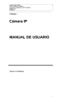
1-2 Example of System
Configuration
The diagram below shows a typical configuration of the camcorder for
ENG and EFP. In this manual, the HDVF-20A HD Electronic
Viewfinder (not supplied) is use to instruct how to operate the unit.
Viewfinder
Viewfinder-related equipment
Fog-proof filter
(Part No. 1-547-341-11)
BKW-401 Viewfinder
Rotation Bracket
HDVF-20A
HD Electronic
Viewfinder
HDVF-C30W
HD Electronic
Viewfinder
Remote control equipment
RCP-700 Series or
RM-B150 Remote
Control Unit
MSU-700A/750
Master Setup Unit
1-6
Chapter 1 Overview
Video monitor for
color image check
while shooting
1
For more information about the fittings, connections, or use of additional
equipment and accessories, see Chapter 5 as well as the operation manuals for the
connected equipment.
Audio signal source
Camera adaptor
HDCA-901 for the input of
the audio channels 3 and
4 and the HD-SDI output
External microphone
C-74, etc.
CAC-12
Microphone Holder
Audio equipment
WRR-810A / 860A
UHF Portable Tuner
Power source
Battery
AC power
supply
100V AC
AC-550
AC Adaptor
BC-L100
Battery
Charger
BP-L60A
Battery Pack
Chapter 1 Overview
1-7
1-3 Precautions
1
Use and Storage
Do not subject the camcorder to severe shocks
The internal mechanism may be damaged or the body warped.
After use
Always turn off the power.
Before storing the camcorder for a long period
Remove the battery pack.
Use and storage locations
Store in a level, ventilated place. Avoid using or storing the camcorder
in the following places.
• Places subject to temperature extremes
• Very damp places
• Places subject to severe vibration
• Near strong magnetic fields
• In direct sunlight or close to heaters for extended periods
To prevent electromagnetic interference from portable
communications devices
The use of portable telephones and other communications devices near
this unit can result in misoperations and interference with audio and
video signals.
It is recommended that the portable communications devices near this
unit be powered off.
Note on laser beams
Laser beams may damage the CCDs. If you shoot a scene that includes a
laser beam, be careful not to let a laser beam become directed into the
lens of the camera.
1-8
Chapter 1 Overview
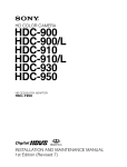
2-1 Power Supply
2
2
4
3
Power supply
1 Battery attachment
Attach a BP-L60A battery pack.
2 DC IN (external power input) connector (XLR type, 4-pin, male)
To operate the HDW-F900 using an AC power supply, connect an AC550 AC Adaptor with the DC output cable supplied with the adaptor.
To use an external battery, connect its DC output cable to the DC IN
connector.
(Continued)
Chapter 2 Locations and Functions of Parts and Controls
2-1
Locations and Functions of Parts and Controls
1
2
3 BREAKER button
If excessive current flows within the unit, the breaker is tripped
automatically to shut off the power supply and protect the equipment.
After performing internal checks or adjustments, use a pointed object
such as a pen to press down lightly on this button. If there is no problem,
the power will again be supplied.
4 POWER switch
This switch turns the main power supply on and off.
2-2
Chapter 2 Locations and Functions of Parts and Controls
2-2 Accessory Attachments
1
2
2
3
4
5
6
7
8
Lens cable clamp
Accessory attachments
1 Shoulder strap posts
Attach the supplied shoulder strap to these posts.
2 Light shoe
Attach an optional accessory such as a video light to this shoe.
3 Lens mount (special bayonet mount)
Use this for mounting the lens.
(Continued)
Chapter 2 Locations and Functions of Parts and Controls
2-3
4 Lens locking lever
After inserting the lens in the lens mount, rotate the lens mount ring with
this lever to lock the lens in position.
2
5 Lens mount cap
Remove this cap by pushing up on the lens locking lever. For protection
from dust, always insert this cap when no lens is mounted.
6 Tripod mount
When using the unit on a tripod, attach the supplied tripod adaptor.
7 LENS connector (12-pin)
Fit the lens cable to this connector. Contact your Sony representative for
more information about the lens you are using.
8 Shoulder pad
You can move the shoulder pad forwards or backwards by loosening the
two screws. Do this to ensure the best balance when shooting with the
camcorder on your shoulder.
2-4
Chapter 2 Locations and Functions of Parts and Controls
2-3 Audio Functions
1
2
2
3
Audio functions (1)
1 Microphone
This is a super-cardioid directional microphone with an external power
supply (+48 V) system. You can use it as an interview microphone by
connecting it to an extension cable (not supplied).
2 MIC IN (microphone input) connector (XLR type, 3-pin, female)
The supplied microphone connects to this connector. You can connect a
microphone other than the supplied one as long as it corresponds to an
external power supply system. The connector supplies power (+48 V) to
the microphone.
3 MIC/MENU knob
This knob adjusts the audio level of the front microphone. To adjust the
front microphone level, set the DISPLAY switch to ON, then push the
MENU switch to CANCEL. The audio level indication will appear on
the viewfinder screen. Note that you can do this only when the AUDIO
SELECT switches are set to MANUAL and the AUDIO IN switches are
set to FRONT.
(Continued)
Chapter 2 Locations and Functions of Parts and Controls
2-5
CH-1
•
•
4
•
•
•
•
•
0
10
5
•
•
AUTO
MANUAL
R-RUN
REGEN
AUDIO SELECT
AUDIO IN
DIAG
REAL
TIME
REAR
CUE IN
OFF
SET
6
FRONT
ON
DF
10
F-RUN
SET
NDF
•
•
•
PRESET
•
•
0
CH-2
LEVEL
•
•
•
•
•
•
SHIFT
•
ADVANCE
•
2
MIX
CH-1
CH-2
7
8
9
0
Audio functions (2)
2-6
Chapter 2 Locations and Functions of Parts and Controls
4 LEVEL (CH-1/CH-2) (audio channel 1 and channel 2 recording
level) controls
These controls adjust the audio levels of channels 1 and 2 when audio
input is from the AUDIO IN CH-1/CH-2 connectors and the AUDIO
SELECT switches are set to MANUAL.
5 AUDIO SELECT (CH-1/CH-2) (audio channel-1 and channel-2
adjustment method select) switches
These switches select the audio level adjustment method for each of
audio channels 1 and 2.
AUTO: Select this setting for automatic adjustment.
MANUAL: Select this setting for manual adjustment.
6 AUDIO IN (CH-1/CH-2) (audio input) switches
These switches select the audio input signals to be recorded for audio
channels 1 and 2.
FRONT: The input signal source is the microphone connected to the
MIC IN connector.
REAR: The input signal source is the audio equipment connected to the
AUDIO IN CH-1/CH2 connectors.
You can also record audio signals in audio channels 3 and 4.
You can select the input signals to be recorded for audio channels 3 and
4 by using the AU REC CH 3/4 item on the VTR SETUP page of the
MAINTENANCE menu.
The following three input signals are available:
1/2 CH: Records the same input signals connected to the AUDIO CH-1/
CH-2 connectors in audio channels 3 and 4..
AUTO: Records inputs signals other than the signals connected to the
AUDIO CH-1/CH-2 connectors, that is signals which are not selected
using the AUDIO IN switches.
This is effective only when the HDCA-901 camera adaptor is turned off,
if connected.
For example: When the CH-1 of the AUDIO IN switch is set to FRONT:
The audio signal input to the AUDIO IN CH-1 connector is recorded in
channel 3.
(Continued)
Chapter 2 Locations and Functions of Parts and Controls
2-7
2
When CH-1 of the AUDIO IN switch is set to REAR:
The signal input to the MIC IN connector is recorded in channel 3.
MUTE: Does not record any input signals in channels 3 and 4.
2
For more information, refer to the Maintenance Manual.
With the HDCA-901 (not supplied) connected to the camcorder, you can
record separate sounds in audio channels 3 and 4.
7 CUE IN (cue track input) switch
This switch selects the input signal to be recorded on the cue track.
CH-1: CH-1 input signal
MIX: Mixed input signals of CH-1 and CH-2
CH-2: CH-2 input signal
8 AUDIO OUT (audio output) connector (XLR type, 5-pin, male)
This connector outputs the audio signals recorded to audio channels 1
and 2 or audio channels 3 and 4.
The PB AUDIO CH item on the VTR SETUP page of the
MAINTENANCE menu allows you to select the audio signal to be
played back.
For more information, refer to the Maintenance Manual.
9 AUDIO IN CH-1/CH-2 (audio channel 1 and channel 2 input)
connectors (XLR type, 3-pin, female) and LINE/MIC/+48 V ON
(line input/microphone input/external power supply +48 V ON)
switches
These are audio input connectors for channels 1 and 2 to which you can
connect audio equipment or a microphone.
The LINE/MIC/+48V ON switches select the audio source of the audio
input signals connected to each of these connectors.
LINE: Line input audio equipment
MIC: Microphone with an internal power supply
+48V ON: Microphone with an external power supply system
0 DC OUT (DC power output) connector
This connector supplies power for a WRR-810A/860A UHF Portable
Tuner (not supplied). Do not connect any equipment other than the UHF
portable tuner.
2-8 Chapter 2 Locations and Functions of Parts and Controls
2
!£ !™ !¡
Audio functions (3)
qa ALARM volume control
This control adjusts the speaker or earphone alarm volume. At the
minimum position, no sound can be heard.
Minimum
Maximum
ALARM volume control
(Continued)
Chapter 2 Locations and Functions of Parts and Controls
2-9
The internal volume control can be adjusted so that the alarm is audible
even if the ALARLı olume control is at the minimum position.
2
For more information, refer to the Maintenance Manual.
qs MONITOR volume control
This control adjusts the speaker or earphone volume for sounds other
than the alarm sound. At the minimum position, no sound can be heard.
MONITOR
CH-1
MIX
CH-2
Minimum
Maximum
MONITOR volume control
qd MONITOR (audio channel select) switch
This switch selects the audio channel to be output from the speaker or
earphone.
CH-1: Channel 1 audio
MIX: Mixed sound of channels 1 and 2
CH-2: Channel 2 audio
During playback, the signals of the audio channels selected from the PB
AUDIO CH item on the VTR SETUP page of the MAINTENANCE
manual are output.
2-10
Chapter 2 Locations and Functions of Parts and Controls
!¢
2
Audio functions (4)
qf Built-in speaker
During recording, the speaker can be used for monitoring the E-E1)
sound, and during playback for monitoring playback sound. The speaker
also sounds alarms to reinforce visual warnings.
If an earphone is plugged into to the EARPHONE jack, the speaker
sound is automatically cut off.
See Section 6-3 “Operation Warnings” (page 6-14) for information about alarms.
....................................................................................................................................
1) E-E sound (Electric-to-Electric sound)
The term E-E sound refers to an audio signal that has passed though the
amplifier, but has not been recorded on the tape. In other words, you can directly
monitor the recording input signal, as opposed to the simultaneous playback
(output) signal.
(Continued)
Chapter 2 Locations and Functions of Parts and Controls
2-11
2
qg
qh
Audio functions (5)
qg EARPHONE jack
You can monitor the E-E sound during recording and playback sound
during playback. Plugging an earphone into the jack automatically cuts
off the built-in speaker, and you hear the alarms about the camcorder's
operation and status through the earphone.
qh Tap for measure hook
This is the hole for the M3 screw (effective screw length: 6mm) located
at the position of the flange focal length. You can use this tap to attach
the hook for a tape measure to measure the distance between the position
of the flange focus and an object. (The effective length of the supplied
screw is 6 mm.)
2-12
Chapter 2 Locations and Functions of Parts and Controls
2-4 Shooting and Recording/
Playback Functions
1
8
2
Eyecup
2
3
4
5
6
7
Shooting and recording/playback functions (1)
1 Viewfinder (When the HDVF-20A (not supplied) is used)
The viewfinder lets you to view the camera image in black and white
while shooting the picture and also see the playback picture from the
VTR. It also displays various warnings and messages related to the
settings or operating conditions of the camcorder, a zebra pattern1), safety
zone marker2), and center marker3).
....................................................................................................................................
1) Zebra pattern
The zebra pattern aids in manual iris adjustment by indicating areas of the
picture where the video level is approximately 70% and 100% and above.
2) Safety zone marker
The safety zone marker is a rectangle indicating the effective picture area.
For more information, see Section 4-8-3 “Setting the Marker Display” (page 4-55).
3) Center marker
The center marker indicates the center of the picture with a crosshair.
(Continued)
Chapter 2 Locations and Functions of Parts and Controls
2-13
2 BRIGHT (brightness) control
This control adjusts the picture brightness on the viewfinder screen. It
has no effect on the camera output signal.
2
3 CONTRAST control
This control adjusts the picture contrast on the viewfinder screen. It has
no effect on the camera output signal.
4 PEAKING control
This control adjusts the sharpness of the picture on the viewfinder screen
to make focusing easier. It has no effect on the camera output signal.
5 DISPLAY/ASPECT (display/aspect control)switch
Use this switch to turn the markers and aspect mask function on or off.
DISPLAY: When MARKER on the MARKER page of the
OPERATION menu is set to ON, pushing this switch to DISPLAY
toggles the markers on the viewfinder screen on and off.
ASPECT: When MASK on the MARKER page of the OPERATION
menu is set to ON, pushing this switch to the aspect mask function
toggles on and off.
6 ZEBRA (zebra pattern) switch
This switch controls the zebra pattern on the viewfinder screen.
ON: The zebra pattern is displayed and stays.
2-14
Chapter 2 Locations and Functions of Parts and Controls
OFF: No zebra pattern is displayed.
MOMENT: The zebra pattern is displayed and stays for 5 to 6 seconds.
The zebra pattern is factory set to indicate picture areas where the
video level is approximately 70%. The setup menu can be used to
specify that areas where the video level is 100% and above are to be
displayed at the same time.
For information about how to set the zebra pattern is to be displayed to indicate
areas of 100% or more, see Section 4-8-5 “Setting the Viewfinder” (page 4-60).
7 TALLY switch
This switch controls the TALLY indicator, setting its brightness (HIGH
or LOW) or turning it off.
HIGH: The TALLY indicator gets brighter.
OFF: The TALLY indicator does not operate.
LOW: The TALLY indicator gets dimmer.
8 Diopter adjustment ring
Use this ring to adjust the viewfinder image for your vision.
(Continued)
Chapter 2 Locations and Functions of Parts and Controls
2-15
2
9
qs
2
q;
qa
Shooting and recording/playback functions (2)
9 Viewfinder left-right positioning ring
Use this ring to move the viewfinder sideways.
0 Viewfinder front-rear positioning lever
Use this lever to move the viewfinder forward or backward.
qa Cameraman tally indicator
This indicator lights while the camcorder is operating.
Slide the window open when you shoot, keeping your eye away from the
viewfinder. This indicator flashes when the battery level is running low
or the tape is nearing its end.
qs Viewfinder stopper
Pull up this stopper to detach the viewfinder from the camera.
2-16
Chapter 2 Locations and Functions of Parts and Controls
2
qd
qf
qg
qh
qj qk ql
Shooting and recording/playback functions (3)
qd FILTER selector
This selector is a dual knob that selects the most appropriate filter to
match the light source illuminating the subject. The outer knob selects
the color temperature of the CC (Color Conversion) filter, and the inner
knob selects the type of ND (Neutral Density) filter. When this selector
is adjusted, the new setting will be indicated on the viewfinder screen for
about 3 seconds. The white balance is stored in memory for each CC
filter.
(Continued)
Chapter 2 Locations and Functions of Parts and Controls
2-17
The relationships between the selector settings and filter selections as
well as examples of filters for different shooting conditions are given
below.
2
FILTER selector (outer) setting and CC filter selection
FILTER selector (outer) setting
CC filter selection
A
5600K
B
3200K
C
4300K
D
6300K
FILTER selector (inner) setting and ND filter selection
FILTER selector (inner) setting
ND filter selection
1
Clear
2
1/4 ND
3
1/16 ND
4
1/64 ND
Examples of shooting conditions and appropriate filters
Shooting condition
CC filter
ND filter
Sunrise and sunset;
inside studio
B (3200 K)
1 (clear)
Clear skies
A (5600 K) or
D (6300 K)
2 (1/4 ND) or
3 (1/16 ND)
Cloudy or raining
D (6300 K)
1 (clear) or
2 (1/4 ND)
Very bright conditions
such as snow, at high
altitudes, or at the seashore
A (5600 K) or
D (6300 K)
3 (1/16 ND) or
4 (1/64 ND)
2-18
Chapter 2 Locations and Functions of Parts and Controls
qf SHUTTER selector
Set this selector to ON to use the electronic shutter. Set it to SEL to
switch the shutter speed or mode setting within the range that has been
previously set from the setup menu.
When this selector is adjusted, the new setting will be indicated on the
setting change/adjustment progress message display area for about 3
seconds.
For more information about the shutter speed and mode settings, see Section 4-2
“Setting the Electronic Shutter” (page 4-9).
qg MIC/MENU knob
When the DISPLAY switch is set to ON or when the lens is using the
automatic iris operation with the DISPLAY switch set to OFF, pressing
and turning the MIC/MENU knob sets the iris override (±1 iris in 1/4 iris
steps). The iris override setting returns to 0 when you turn off the
camcorder, then on again.
qh AUTO W/B BAL (automatic white/black balance adjustment)
switch
This switch activates the white balance and black balance automatic
adjustment functions.
WHT: Automatic adjustment of the white balance. If the WHITE BAL
switch is set to A or B, the white balance setting is stored in the
corresponding memory. The memory can store the white balance
setting for each CC filter.
BLK: Automatic adjustment of the black set and black balance.
(Continued)
Chapter 2 Locations and Functions of Parts and Controls
2-19
2
2
qj GAIN selector
This selector switches the gain of the video amplifier to match the
lighting conditions during shooting. The gains corresponding to the L,
M, and H settings are selected from the setup menu before use. The
factory settings are L = 0 dB, M = 6 dB, and H = 12 dB.
When this selector is adjusted, the new setting will be indicated on the
setting change/adjustment progress message display area of the
viewfinder screen for about 3 seconds.
For information about setting the gain values, see Section 4-8-4 “Setting the GAIN
Selector Values” (page 4-58).
qk OUTPUT/DCC (output signal/dynamic contrast control) selector
This selector switches the video signal that is output to the VTR,
viewfinder, and video monitor, between the color bar signal and the
camera output.
BARS: Outputs the color bar signal. The DCC indicator automatically
goes off. When the AU REC 1 KHz item on the VTR SETUP page of the
MAINTENANCE menu is set to either 0 dB or -20 dB, the 1-kHz audio
signal is also output with the color bar signals.
CAM: Outputs the camera signal. It also switches DCC1) on and off
when output from the camera is selected.
....................................................................................................................................
1) DCC (Dynamic Contrast Control)
Also called automatic knee. Against a very bright background with the iris
opening adjusted to the subject, objects in the background will be lost in the
glare. The DCC function will suppress the high intensity and restore much of the
lost detail and is particularly effective in the following cases.
• Shooting a subject against a bright sky
• Shooting a subject indoors, against a background through a window
• Any high contrast scenes
2-20
Chapter 2 Locations and Functions of Parts and Controls
BARS, DCC OFF
A color bar signal is output and the DCC
circuit does not operate. For example, use
the setting for the following purposes.
• Adjusting the video monitor
• Recording the color bar signal
OUTPUT
BARS CAM
•
•
•
OFF
•
ON
DCC
CAM, DCC OFF
The video signal from the camera is
output, and the DCC circuit does not
operate.
CAM, DCC ON
The video signal from the camera is
output, and the DCC circuit operates.
OUTPUT/DCC selector
ql WHITE BAL (white balance memory) switch
This switch determines the source of the white balance settings.
PRST (preset): Adjusts the color temperature corresponding to the
position of the FILTER selector (outer knob). Use the PRST setting
when you have no time to adjust the white balance.
A or B: When the AUTO W/B BAL switch is pushed to WHT, the white
balance is automatically adjusted according to the current position of
the FILTER selector (outer knob), and the adjusted value is stored in
either memory A or memory B. (There are two memories for each
CC filter, so a total of eight adjustments can be stored.) When the
FILTER selector (outer knob) is at the same position as it was when
this WHITE BAL switch was adjusted, the stored value is called from
memory, and the camcorder automatically adjusts itself to that value.
When this switch is adjusted, the new setting will be indicated on the
setting change/adjustment progress message display area of the
viewfinder screen for about 3 seconds.
(Continued)
Chapter 2 Locations and Functions of Parts and Controls
2-21
2
2
w;
wa
Shooting and recording/playback functions (4)
w; GENLOCK IN (genlock input) connector (BNC type)
This connector inputs an HD reference signal when the camera is to be
genlocked or when the time code is to be synchronized with external
equipment. Use the MAINTENANCE menu to adjust the genlock Hphase (phase of Horizontal sync signal).
For details, refer to the Maintenance Manual.
Also, assigning the RETURN function to the assignable switch allows
you to view the image of the input signal on the viewfinder.
For details, see “4-8-8 Setting the D5600K Mode, Assignable Switches and PB
VIDEO” on page 4-66.
2-22
Chapter 2 Locations and Functions of Parts and Controls
wa REMOTE (remote control) connector (8-pin)
Connect the RCP-700 Series or RM-B150 Remote Control Unit (not
supplied) with which VTR control is possible. You can also connect and
use the MSU-700A/750 Master Setup Unit (not supplied).
ws
Shooting and recording/playback functions (5)
ws MONITOR OUT connector (BNC type)
This connector outputs the HD video signal (75-ohm terminated, Y/PB/
PR). To include the text on the viewfinder screen with the output signal,
push the DISPLAY switch to MENU while pushing the MENU switch to
CANCEL. Text output is cancelled when you turn the camcorder off,
then on again.
(Continued)
Chapter 2 Locations and Functions of Parts and Controls
2-23
2
2
@£
@¢
@∞
@§
@¶
EJEC
T
6
REW
0
P
STOp
D
F FW
)
@•
@ª
PLAY
(
Opening the cover
1
Press on the tab.
Shooting and recording/playback functions (6)
2-24
Chapter 2 Locations and Functions of Parts and Controls
2
wd VTR START button
Press this button to start recording. Press it again to stop recording. The
effect is exactly the same as that of the VTR button on the lens.
wf VTR SAVE/STBY (VTR power saving/standby) switch
This switch controls the VTR power mode during pauses in recording
(REC PAUSE).
SAVE: Power saving mode. When you press the VTR START button,
there is a short delay before recording starts, but power consumption
is less than in standby mode, and battery life is extended. When the
switch is set to SAVE, the VTR SAVE indicator in the viewfinder
lights.
STBY: Standby mode. Recording starts as soon as you press the VTR
START button. Avoid allowing the camcorder to remain in STBY
(standby) mode for a long time.
wg EJECT (cassette eject) button
Press this button to eject or load a cassette.
wh REW (rewind) button and indicator
Press this button to rewind the tape. The indicator lights during
rewinding.
(Continued)
Chapter 2 Locations and Functions of Parts and Controls
2-25
2
wj F FWD (fast forward) button and indicator
Press this button to fast forward the tape. The indicator lights during fast
forward.
2
wk PLAY (playback) button and indicator
Press this button to view the recorded picture in the viewfinder or on the
color video monitor. The indicator lights during playback.
The 3 times normal speed search function is provided to make it far
quicker to find a desired location of the tape. Press the REW button or F
FWD button during playback to view the 3 times normal speed search
picture.
wl STOP button
Press this button to stop the tape.
2-26
Chapter 2 Locations and Functions of Parts and Controls
2-5 Setup Menu Operating
Section
2
1
2
34
5
Setup menu operating section
1 Memory Stick compartment
Open the cover of the Memory Stick compartment. Insert the Memory
Stick (not supplied) with the notch facing upward and the label facing
toward you into the slot.
2 MIC/MENU knob
Use this knob to change the page selection or a setting within the setup
menu.
(Continued)
Chapter 2 Locations and Functions of Parts and Controls
2-27
2
3 MENU switch
Push this switch to CANCEL to erase the menu settings and return to
page selection mode or the TOP menu. Push the switch up to display the
‘!’ IND page of the operation menu.
For details on settings of this page, see Section 4-8-2“Selecting the Items for
Which the ‘!’ IND is to Light” (page 4-50).
4 DISPLAY switch
Use this switch to change the display on the viewfinder screen.
ON: A message or character indicating the camcorder's settings or
operation status is displayed on the viewfinder screen.
OFF: The display on the viewfinder screen disappears.
MENU: The setup menu is displayed on the viewfinder screen.
5 Assignable switches 1/2
You can assign the desired functions to each of assignable switch on the
OTHERS page of the OPERATION menu.
For details, see “4-8-8 Setting the D5600K Mode, Assignable Switches and PB
VIDEO” on page 4-66.
2-28
Chapter 2 Locations and Functions of Parts and Controls
2-6 Time Code System
2
1
Time code functions (1)
1 GENLOCK IN (genlock input) connector (BNC type)
This connector inputs an HD reference signal when the camera is to be
genlocked or when the time code is to be synchronized with external
equipment.
By assigning the RETURN function to the assignable switch(es), you
can see the image of the return video signal on the viewfinder.
For details, see “4-8-8 Setting the D5600K Mode, Assignable Switches and PB
VIDEO” on page 4-66.
(Continued)
Chapter 2 Locations and Functions of Parts and Controls
2-29
2
2
3
Time code functions (2)
2 TC IN (time code input) connector (BNC type)
To synchronize the time code with an external time code, connect the
reference time code input here.
3 TC OUT (time code output) connector (BNC type)
To synchronize the time code of an external VTR with that of the
camcorder, connect this connector to the time code input lock connector
of the external VTR.
2-30
Chapter 2 Locations and Functions of Parts and Controls
2
DISPLAY
WARNING
CTL
TC
HOLD
4
LIGHT
RESET
ON
5
OFF
CH-1
•
•
•
•
0
•
•
•
•
•
10
10
•
•
MANUAL
REGEN
AUDIO SELECT
AUDIO IN
REAL
TIME
FRONT
REAR
ON
NDF
•
AUTO
SET
DIAG
!¡
!™
•
F-RUN
R-RUN
DF
•
•
0
PRESET
CH-2
LEVEL
•
•
•
•
•
•
SHIFT
•
ADVANCE
7
8
9
0
6
U-BIT
CUE IN
OFF
SET
MIX
CH-1
CH-2
Time code functions (3)
(Continued)
Chapter 2 Locations and Functions of Parts and Controls
2-31
2
4 HOLD (display hold) button
Pressing this button instantly freezes the time data displayed in the
counter display section. (The time code generator continues normal
operation.) Pressing this button again releases the hold. One use of this
feature is to determine the exact time of a particular shot.
When the HOLD button is activated, the time data is dsiplayed in the
following format:
See Section 2-8 “Warnings and Indications on the Display Panel” (page 2-38) for
more information about the counter display.
5 RESET (counter reset) button
This button resets the time data displayed on the counter display section
to “00:00:00:00” and the user bit data to “00000000".
6 DISPLAY (LCD) switch
Depending on the settings of the F-RUN/SET/R-RUN switch and the
REAL TIME switch, this switch selects data to display in the counter
display section as follows:
CTL: Control signal
U-BIT: User bits
TC: Time code
For more information, see “Time code displays” (page 2-40).
7 ADVANCE button
For setting the time code, user bits, or real time, each press of this button
increments the flashing digit selected by the SHIFT button.
2-32
Chapter 2 Locations and Functions of Parts and Controls
8 SHIFT button
For setting the time code, user bits, or real time, this button selects the
digit to be changed. The selected digit flashes.
9 PRESET/REGEN (preset/regeneration) switch
This switch selects whether to set a new time code or to match the
existing time code that had been recorded.
PRESET: Starts recording time code values on the tape from the newly
set value.
REGEN: Reads the existing time code on the tape and sets the time code
starting value accordingly. Thus, even when there is an indefinite
break in recording, this setting ensures that time codes on the tape
will be continuous. Regardless of the setting of the F-RUN/SET/RRUN switch, the camcorder operates in R-RUN mode.
For more information, see “Make the time code continuous” on page 4-20.
0 F-RUN/SET/R-RUN (free run/set/recording run) switch
This switch selects the operating mode for the internal time code
generator.
F-RUN: The time code generator keeps running, regardless of the
operation state of the VTR. Use this position when matching the time
code to real time or for synchronizing the time code with an external
time code.
SET: Set the switch to this position to set the time code or user bits.
R-RUN: The time code generator runs only while recording. This
produces a tape with consecutive time code value, even when shot
intermittently.
For more information, see Section 4-4-1 “Setting the User Bits” (page 4-17) and
Section 4-4-2 “Setting the Time Code” (page 4-19).
(Continued)
Chapter 2 Locations and Functions of Parts and Controls
2-33
2
2
qa DF/NDF (drop frame/non-drop frame) switch
This switch selects whether the time code advances in drop frame mode
or non-drop frame mode. This switch is effective only when the format is
set to one of 29.97 PsF, 30 PsF, 59.94 I or 60 I in the MULT FORMAT
page of the MAINTENANCE menu.
DF: Drop frame mode1)
NDF: Non-drop frame mode2)
qs REAL TIME switch
This switch selects whether or not real time is to be recorded as VITC
user bit data. It is also used for setting the real time.
ON: Real time is recorded as VITC user bit data.
OFF: Real time is not recorded as VITC user bit data.
SET: Sets the real time.
....................................................................................................................................
1) Drop frame mode
To eliminate the discrepancy between the actual time and the time code value
generated by the time code generator when the format is set to either 29.97 PsF
or 59.94 I in the MULT FORMAT page of the MAINTENANCE menu, drop
frame mode drops two frames (frames 00 and 01) from the time code value at
the beginning of each minute except every tenth minute.
2) Non-drop frame mode
Non-drop frame mode does not perform the processing of drop frame mode. As
a result, when the format is set to either 29.97 PsF or 59.94 I in the MULT
FORMAT page of the MAINTENANCE menu, there will be a discrepancy
between the actual time and the time code value of about 86 seconds per one day
of recording. In case of 30 PsF and 60 I, a discrepancy will not occur.
2-34
Chapter 2 Locations and Functions of Parts and Controls
2-7 Warnings and Indications
The camcorder supplies you visual information and warnings by means
of its indicators without you having to use the speaker, earphone or
viewfinder.
2
1
2
PRESET
F-RUN
SET
R-RUN
REGEN
3
DIAG
REAL
TIME
ON
DF
NDF
OFF
SET
4
5
6
7
8
Warning and indication functions
(Continued)
Chapter 2 Locations and Functions of Parts and Controls
2-35
2
1 TALLY indicator
Setting the TALLY switch to HIGH or LOW activates this indicator. The
indicator lights during recording on the VTR. It also provides the same
information as the REC indicator in the viewfinder; it lights up during
recording and flashes to indicate a problem. The brightness of this
indicator when it is lit can be controlled by the TALLY switch.
2 TALLY switch
This switch controls the TALLY indicator, setting its brightness (HIGH
or LOW) or turning it off.
HIGH: The TALLY indicator gets brighter.
OFF: The TALLY indicator does not operate.
LOW: The TALLY indicator gets dimmer.
3 DIAG (self-diagnostics) button
Pressing this button when the VTR is stopped switches the camcorder to
self-diagnostics mode. In self-diagnostics mode, it is possible to carry
out a display panel test, a VTR test, or a camera test and display the test
result.
To exit from self-diagnostics mode, press this button once more.
For more information, refer to the Maintenance Manual.
4 BACK TALLY indicator
This indicator functions exactly the same way as the front tally indicator
when the BACK TALLY switch is set to ON.
5 BACK TALLY switch
This switch enables (ON) or disables (OFF) the operation of the BACK
TALLY indicator.
ON: Enables the BACK TALLY indicator operation.
OFF: Disables the BACK TALLY indicator operation.
2-36
Chapter 2 Locations and Functions of Parts and Controls
6 WARNING indicator
This indicator lights up or flashes when there is a fault in the VTR.
See Section 6-3 “Operation Warnings” (page 6-14) for more information about the
relationships between the operation of the indicator and the meanings of the
indications.
7 LIGHT switch
This switch controls the display panel light.
ON: Turns the panel light on.
OFF: Turns the panel light off.
8 Display panel
VTR error messages, battery status, tape status, audio level, time data,
and so forth are displayed on this panel.
For more information, see Section 2-8 “Warnings and Indications on the Display
Panel” (page 2-38).
Chapter 2 Locations and Functions of Parts and Controls
2-37
2
2-8 Warnings and Indications
on the Display Panel
Tape status, battery status, and level indicators
2
Audio channel 1 level meter
Audio channel 2 level meter
DIAG PB VITC NDF EXT-LK
HOLD
V
H
H
MIN
SEC
E
B
BATT
E
F
SERVO
HUMID
0
10
FRM
TAPE
RF
OVER EMPH OVER
SLACK
20
30
40
PEAK dB
Battery status indicator
BATT
E
F
Fully charged
Nearly dead: “BATT” flashes.
Dead battery (battery must be charged):
“BATT” and “E” flash.
Tape status indicator
TAPE
E
B
Full (at beginning)
Close to end: “TAPE” flashes.
End (tape must be replaced):
“TAPE” and “E” flash.
Tape status, battery status, and level indicators
2-38
Chapter 2 Locations and Functions of Parts and Controls
VTR operation status and status indicators
Lights in the self-diagnostic mode (testing
display panel, camera, and VTR).
2
For more information, refer to the
Maintenance Manual.
Lights during playback.
DIAG PB VITC NDF EXT-LK
HOLD
OVER EMPH OVER
0
10
H
MIN
SEC
FRM
TAPE
E
B
BATT
E
F
RF
SERVO
HUMID
SLACK
20
30
40
PEAK dB
Warning indicators
RF: Lights if the recording heads are clogged.
SERVO: Lights if the servo motor fails.
HUMID: Lights if condensation is on the drum.
SLACK: Lights if the tape is not winding properly.
For more information, see Section 6-3 “Operation Warnings” (page 6-14).
VTR operation and status indicators
Note
If the tape in the VTR becomes slackened, an error code appears
automatically on the display section of the display panel.
For more information refer to the Maintenance Manual.
Chapter 2 Locations and Functions of Parts and Controls
2-39
Time code displays
Lights in playback mode.
2
Lights when VITC is selected for the time code.
Lights in non-drop frame mode.
Lights when the camcorder is synchronized with
an external time code.
Lights when the time code
generator is on hold.
DIAG PB VITC NDF EXT-LK
HOLD
V
H
H
MIN
SEC
E
B
BATT
E
F
SERVO
HUMID
0
10
FRM
TAPE
RF
OVER EMPH OVER
SLACK
20
30
40
PEAK dB
Lights when the time code, CTL, or
real time is displayed.
Lights in the following way when the HOLD button
is pressed.
Time counter display: Shows the time code, CTL, user bits,
and real time.
The table on the next page lists the details of the displayed
items and switch settings.
Time code displays
2-40
Chapter 2 Locations and Functions of Parts and Controls
Relationships between the REAL TIME, F-RUN/SET/R-RUN,
and DISPLAY switch settings and the time counter displays
The time counter display is determined first by the REAL TIME switch
setting, then by the F-RUN/SET/R-RUN switch setting, and finally by
the DISPLAY switch setting.
Switch settings related to time code and displayed information
REAL TIME
F-RUN/SET/R-RUN
switch position switch position
ON or OFF
SET
F-RUN or R-RUN
SET
Any position
DISPLAY switch Displayed
position
information
TC or CTL
Time code
U-BIT
User bits
CTL
CTL
TC
Time code
U-BIT
User bits
Any position
Acrual time
Chapter 2 Locations and Functions of Parts and Controls
2-41
2
2-9 Indicators on the
Viewfinder (HDVF-20A
(not supplied))
2
1
TALLY/REC
BATT
2
3
Viewefinder
screen
4
VTR
SAVE
5
Indicators on the Viewfinder
1 TALLY indicator
Not used in the camcorder.
2 BATT indicator
Starts flashing when the battery voltage supplied to the camcorder drops
below the minimum level, and stays lit when the battery is exhausted.
To prevent interruption during operation, replace the battery as soon as
this indicator starts flashing.
2-42
Chapter 2 Locations and Functions of Parts and Controls
The level at which the indicator starts flashing can be set on the BATT
ALARM page of the MAINTENANCE menu. Also, you can confirm the
set alarm voltage on the BATT ALARM page of the OPERATION
menu.
For more information, see “4-8-7 Setting the Battery” on page 4-64.
3 TALLY/REC indicator (red)
Depending on the status, this indicator will light up or flash.
When lit: The image shot by the camera is being recorded.
Note
This indicator will be brighter than usual for a moment after it is first lit.
This is only a warning, and not a malfunction.
When flashing: The servo system of the VTR section is unlocked and so
on.
For more information on the status by which the TALLY/REC indicator will light or
flash, see “6-3 Opeation Warnings” on page 6-14.
4 VTR SAVE indicator
Lights up when the VTR section is set to power save mode by setting the
VTR SAVE/STBY switch to SAVE.
5 (warning) indicator
Lights up when the settings of the camcorder are changed from the ones
set on the “IND” page of the OPERATION menu.
For details, see “4-8-2 Selecting the Items for Which the ‘!’ IND is to Light” on
page 4-50.
Chapter 2 Locations and Functions of Parts and Controls
2-43
2
3-1 About Cassettes
This section describes the procedure for loading and unloading a
cassette.
See “Specifications VTR Section ”(page A-3) for information about the cassettes
you can use in the camcorder.
3-1-1 Loading and Unloading a Cassette
3
Loading a cassette
Recording and Playback
1
Turn on the POWER switch.
POWER switch
HUMID display
Note
If the interior of the VTR section is damp, the HUMID indicator will
light. If this happens, wait until the indicator goes off before going
on to step 2.
(Continued)
Chapter 3 Recording and Playback
3-1
2
Press the EJECT button.
The cassette lid will open.
Cassette lid
3
3
Check that there is no slack in the tape. Then slide in the cassette
until it clicks into position and close the cassette lid completely by
pressing near the engraved “PUSH".
1 Insert the cassette.
Window outward
Cassette holder
2 Push and close the
cassette lid.
Notes
• To insert the tape correctly, make sure the tape in the cassette is facing
up towards you before you try to close the cassette lid.
• When inserting the tape, be careful that you don’t hit the tape against
the tape holder.
3-2
Chapter 3 Recording and Playback
Checking the tape for slack
Pressing in the reels lightly, turn them gently with your fingers in the
directions shown below. If the reels will not move, there is no slack.
3
Checking the tape for slack
Unloading a cassette
With the power supply on, press the EJECT button to open the cassette
lid. Then take out the cassette. If you are not going to insert another
cassette, close the cassette lid.
It is possible to take out the cassette and close the cassette lid unless the
battery voltage drops below about 10.5 V. Do not repeat this unloading
operation.
Chapter 3 Recording and Playback
3-3
Unloading a cassette manually
If the battery voltage drops below about 10.5 V, take out the cassette
manually as illustrated below.
3
Cassette lid
1 Turn the power off.
2 Open this rubber cover.
3 Pushing on the screw inside
with a screwdriver, turn
the screw counterclockwise
until the cassette lid opens.
Unloading a cassette manually
You need not return the screw to its original position after taking out the
cassette. Although the cassette lid is not locked, turning on the power
makes the cassette lid operable again.
3-1-2 Preventing Accidental Erasure
The following procedure prevents cassettes from being recorded
inadvertently.
Push the plug in. To
reuse the cassette,
return the plug to its
original position.
Preventing accidental erasure
3-4
Chapter 3 Recording and Playback
3-2 Recording
3-2-1 Basic Procedure
This section describes the basic procedure for shooting and recording.
Before a shooting session, ensure that the camcorder is functioning
properly.
For more information, see Section 6-1 “Testing the Camcorder Before Shooting”
(page 6-1).
Turning on the camcorder and loading a cassette
Follow the procedure below.
4
3 1
2
•
•
•
•
•
•
•
•
•
•
•
•
•
•
•
•
•
•
•
•
•
•
Basic procedure for shooting : from power supply to cassette loading
1
Attach a fully charged battery pack.
For details, see “5-1 Power Supply” on page 5-1.
2
Set the POWER switch to ON. Check that the HUMID indicator
does not appear and that the BATT indicator shows at least five
segments.
• If HUMID indicator appears, wait until it disappears.
• If the BATT indicator does not show at least five segments,
replace the battery pack with a fully charged one.
(Continued)
Chapter 3 Recording and Playback
3-5
3
3
Check that there are no obstructions near the cassette lid. Then press
the EJECT button to open the cassette lid.
4
After checking the points below, load the cassette and close the
cassette lid.
• The cassette is not write-protected.
• There is no slack in the tape.
3
Basic procedure for shooting: from adjusting the
black balance and white balance to stopping recording
After turning on the power and loading a cassette, set the switches and
selectors as shown below and begin operation.
Iris: Automatic
AUDIO SELECT
CH-1/CH-2:
AUTO
•
•
•
•
•
•
•
•
•
•
•
•
•
•
•
•
•
•
•
•
•
•
Zoom:
Automatic
GAIN: Set as low
as possible.
OUTPUT/DCC:
CAM, DCC ON
F-RUN/SET/R-RUN:
F-RUN or R-RUN
(set as needed)
Switch and selector settings before shooting
3-6
Chapter 3 Recording and Playback
Shooting
Follow the procedure below.
2
•
•
•
•
•
•
3
•
•
•
•
•
•
•
•
•
•
•
•
•
•
3,5
•
•
1,2
4
5,6
Basic procedure for shooting: from adjusting the black balance and white
balance to stopping recording
1
Push the AUTO W/B BAL switch to BLK to adjust the black
balance.
For detailed information on how to adjust the black balance, see “4-1-1
Adjusting the Black Balance” on page 4-2.
2
Select the CC filter and ND filter to match the lighting conditions,
and adjust the white balance.
(Continued)
Chapter 3 Recording and Playback
3-7
When the black balance and white balance settings are already in
memory:
Set the WHITE BAL switch to A or B.
When the white balance setting is not in memory and you do not
have enough time to adjust the white balance:
Set the WHITE BAL switch to the PRST position. The white
balance is automatically set to 3200 K when the FILTER selector is
set to B, to 4300 K when the FILTER selector is set to C, and to
6300 K when the FILTER selector is set to D.
3
For more information, see Section 4-1-2 “Adjusting the White Balance”
(page 4-5).
3
Aim the camera at the subject and adjust the focus and zoom.
4
If necessary, set the electronic shutter for an appropriate mode and
speed.
For more information, see Section 4-2 “Setting the Electronic Shutter”
(page 4-9).
5
To start recording, press the VTR START button or the VTR button
on the lens.
Or if the VTR S/S function is assigned to either of the assignable
switches 1/2, these assignable switches function as VTR START/
STOP buttons.
For details, see “4-8-8 Setting the D5600K Mode, Assignable Switches and
PB VIDEO” on page 4-66.
During recording, the REC indicator in the viewfinder goes on.
Perform zooming and focus control, if necessary.
6
To stop recording, press the VTR START button or the VTR button
on the lens again.
The REC indicator goes off.
3-8
Chapter 3 Recording and Playback
Cassette control buttons
During recording, the cassette control buttons (EJECT, REW, F FWD,
PLAY, STOP) have no effect.
3-2-2 Continuous Recording
If the camcorder is in the recording pause mode, simply pressing the
VTR START button on the camcorder or the VTR button on the lens
continues recording at exactly the next frame.
In other cases, you first need to position the tape at an appropriate point.
When the camcorder is in the recording pause mode
Pressing the VTR START button on the camcorder or the VTR button on
the lens positions the tape at the appropriate point automatically.
However, the time taken before recording starts depends on the setting of
the VTR SAVE/STBY switch.
• If the VTR SAVE/STBY switch is in the SAVE position, it takes about
4 seconds before recording starts.
• If the VTR SAVE/STBY switch is in the STBY position, recording
starts immediately. However, just after the switch position is changed
from SAVE to STBY, it takes about 4 seconds before recording starts.
Chapter 3 Recording and Playback
3-9
3
If you turn off the power during a recording pause
3
2
1
3
Continuous recording after turning off the power during a recording pause
1
Turn on the power again.
2
Press the RET button on the lens.
The camcorder positions the tape at the appropriate point. Note,
however, that this function works only for continuously recorded
material or consecutively joined segments totaling at least 4 seconds
in length.
3
Press the VTR START button on the camcorder or the VTR button
on the lens to start recording.
3-10
Chapter 3 Recording and Playback
Continuous recording in other cases
After rewinding or fast forward, after removing the cassette, or on a tape
that has been partially recorded, you can obtain a continuous recording
by following the procedure below.
Note
If the tape is recorded with a format which is different from the format
for the camcorder selected on the MULT FORMAT page of the
MAINTENANCE menu, trecording may not continu smoothly. Noise
and so on occurs at the point where recordings are continued.
12
3
4
Continuous recording after rewinding or fast forward, after removing the
cassette, or on a tape that has been partly recorded
1
Looking in the viewfinder, press the PLAY button to start playback.
2
Press the STOP button at the desired point to begin recording. To
continue from the end of recording already on the tape, press the
STOP button immediately after the end of the previous recording
(within 0.5 seconds).
(Continued)
Chapter 3 Recording and Playback
3-11
3
3
Press the RET button.
The tape will rewind and will be positioned at the desired point to
continue recording.
3
4
Press the VTR START button on the camcorder or the VTR button
on the lens to start recording.
3-12
Chapter 3 Recording and Playback
3-3 Checking the Recording
— Playback
By pressing the PLAY button, you can review any length of recording in
the viewfinder in black and white. There are three other ways to review
the recording.
• Recording review: You can view the last 3 seconds of the recording in
the viewfinder in black and white.
• Color playback: You can see the recording in color on a color video
monitor without the need for any external adaptor.
• Color playback/camera picture: The menu allows you to change the
settings so that you can see images as seen by the camera on the
viewfinder or on the HD monitor connected to the MONITOR OUT
connector even during playback. In this case, if you attach an
HDCA-901 Camera Adaptor, you can see the recorded images on an
HD monitor connected to the HDCA-901.
Note
To use this function, you have to choose the settings for the output
signal.
For detailed information, see "4-8-8 Setting the D5600K Mode, Assignable
Switches and PB VIDEO" on page 4-66.
You may also view the picture by pressing the PLAY + REW button or
PLAY + F FWD button during searching by rewinding or fast
forwarding.
See Section 2-3 “Audio Functions” (page 2-5) for information about the switches
and controls used to select the audio output signal and to adjust the audio level.
Note
When a tape recorded in a different format is played back, a warning
message appears in the display window during playback.
Example: When the format of the recorded tape is 59.94I and the format
of the camcorder is set to 23.98 PsF, the message “59 - - 23” appears.
Chapter 3 Recording and Playback
3-13
3
3-3-1 Checking the Last Three Seconds of the
Recording — Recording Review
3
If you press the RET button on the lens while recording is paused, the
last three seconds of the tape is automatically rewound, and that segment
is played back on the viewfinder screen. Use this function to check
whether recording went smoothly. If you hold the RET button down
longer, at most 10 seconds of the tape is rewound and played back. After
playback, the camcorder is ready to start recording again.
By assigning the LENS RET function to the assignable switch(es) using
the OPERATION menu, you can use the assignable switch(es) in the
same way as the RET button on the lens.
For details, see “4-8-8 Setting the D5600K Mode, Assignable Switches and PB
VIDEO” on page 4-66.
Note
The recording review functions only works if the recording you have
made is at least 3 seconds long.
3-3-2 Checking the Recording on the Color
Video Monitor — Playback in Color
Connect a color video monitor to the MONITOR OUT connector of the
camcorder and press the PLAY button.
HDW-F900
HD monitor
Video input
connector
MONITOR OUT
Color playback
3-14
Chapter 3 Recording and Playback
3-3-3 Checking the Camera Picture on the
Viewfinder and/or Color Video Monitor
Usually, during playback of a tape, if you press the PLAY button, the
image sent to the viewfinder or the MONITOR connector is switched
back and forth between the camera image and to recorded image.
However, the PB VIDEO item on the OTHERS page allows you to
change the setting so that the image seen through the camera is sent to
the viewfinder and the MONITOR OUT connector even while you are
playing back a video tape.
The HD SDI output from the HDCA-901 Camera Adaptor (not supplied)
is switched to that of the recorded image during the playback regardless
of the PB VIDEO setting.
For detailed information, see "4-8-8 Setting the D5600K Mode, Assignable
Switches and PB VIDEO" on page 4-66.
HD monitor
HDCA-901
HDW-F900
HD SDI input
connector
HD monitor
HD SDI OUT
connector
MONITOR OUT
Video input connector
Chapter 3 Recording and Playback
3-15
3
3-4 Tele-File
The VTR section is compatible with the Tele-File memory label system.
This system allows you to record the recording start timecode and shot
markers onto the MLB-1M 100 memory label (not supplied).
Follow the procedure below to record the starting timecode and shot
markers.
3
1
Insert the cassette onto which the MLB-1M-100 memory label has
been attached.
2
Press the VTR START button or the VTR button on the lens.
At the instant the recording starts, the timecode of the recording start
is recorded on the memory label.
3
While shooting, press the RET button on the lens to create the shot
marker.
The timecode valid when you press the RET button is recorded on
the label as the shot marker.
To confirm that the RET button is pressed
Set the DISPLAY switch to ON.
Whenever you press the RET button, the circle lights up on the right
side of the REC lamp in the viewfinder.
Note
If you set the POWER switch to OFF within 1 second after a recording
pause, the recorded data is not guaranteed.
To clear recorded data
For detailed information on how to clear data, see the maintenance manual.
....................................................................................................................................
1) Shot marker: Time code to be used as the editing point when editing.
3-16
Chapter 3 Recording and Playback
4-1 Adjusting the Black
Balance and the White
Balance
To always obtain excellent image quality when using this camcorder,
conditions may require that both the black balance and the white balance
be adjusted.
Black balance adjustment
White balance adjustment
Always readjust the white balance when the lighting conditions change.
Viewfinder screen displays
When the black balance, white balance adjustment or white spots
correction is started, messages that report on the progress and results are
displayed on the viewfinder screen.
Note
Black balance and white balance adjustment values that are
automatically set by the camcorder and the various settings are stored in
the camcorder memory and retained even when the power is turned off.
Chapter 4 Adjustments and Settings for Recording
4-1
4
Adjustments and Settings for Recording
The black balance will require adjustment in the following cases.
• When the camcorder is first used
• When the camcorder has not been used for a long time
• When the camcorder is used under conditions in which the surrounding
temperature has changed greatly
• When the GAIN selector values have been changed by using the setup
menu
It is not usually necessary to adjust the black balance when using the
camcorder after it has been briefly off.
4-1-1 Adjusting the Black Balance
In automatic black balance mode, adjustments are performed in the
following order: clamp level, black set, and black balance. Manual black
balance adjustment can be selected from the setup menu.
Follow the procedure below to adjust the black balance.
4
1
Set the switches as shown in the figure below.
GAIN switch:
Set as low as
possible.
OUTPUT/DCC
switch: CAM
DISPLAY switch: OFF
4-2
Chapter 4 Adjustments and Settings for Recording
2
Push the AUTO W/B BAL switch to BLK and release the switch.
4
AUTO W/B BAL switch
The switch returns to the center position, and the adjustment is
completed.
During adjustment, the following message is displayed on the viewfinder
screen.
ABB:EXECUTING
The black balance adjustment ends in a few seconds with the message
“ABB:OK” and the adjustment setting is automatically stored in
memory.
(Continued)
Chapter 4 Adjustments and Settings for Recording
4-3
Notes
• During the black balance adjustment, the iris is automatically closed.
• During the black balance adjustment, the gain selection circuit is
automatically activated so you may see flickering on the viewfinder
screen, but this is not a fault.
4
If automatic black balance adjustment cannot be made
If the black balance adjustment cannot be completed normally, the error
message “ABB:NG” will appear for about 3 seconds on the viewfinder
screen. If this error message is displayed, retry the black balance
adjustment. If the error message occurs again, an internal check is
necessary.
Refer to the Maintenance Manual for information about this internal check.
Black balance memory
Values stored in memory are retained even when the camcorder power is
turned off.
4-4
Chapter 4 Adjustments and Settings for Recording
4-1-2 Adjusting the White Balance
Follow the procedure below to automatically adjust the white balance.
1
Adjust the switches as shown in the figure below.
FILTER selector
4
OUTPUT/DCC switch:
CAM
GAIN switch:
Set as low as
possible.
WHITE BAL switch:
A or B
DISPLAY switch: OFF
If the setting on the GAIN selector or WHITE BAL switch is changed, a
message reporting the set position appears for about 3 seconds in the
setting change and adjustment progress message display area of the
viewfinder screen.
(Continued)
Chapter 4 Adjustments and Settings for Recording
4-5
2
Adjust the FILTER selector to suit the lighting conditions.
ND filter
CC filter
1
Clear
A
5600K
2
1/4 ND
B
3200K
3
1/16 ND
C
4300K
4
1/64 ND
D
6300K
If the setting of the FILTER selector is changed, a message reporting
the setting appears for about 3 seconds in the setting change and
adjustment progress message display area of the viewfinder screen.
4
3
Place a white test card under the same lighting conditions as the
subject to be shot and zoom up to it. Alternately, any white object
such as a cloth or a wall could be used.
The absolute minimum white area is as follows:
Rectangle centered on the
screen. The lengths of the
sides are 70% of the length
or the width of the screen.
The white object must be
within the rectangle and
have an area of at least
10% of the screen.
4-6
Chapter 4 Adjustments and Settings for Recording
Note
Make sure there are not bright spots in the rectangle.
4
Adjust the lens iris.
If the lens is manually adjusted, adjust it as appropriate.
If the lens has an automatic iris, set the automatic/manual switch on
the lens to automatic.
5
Push the AUTO W/B BAL switch to WHT and release the switch.
AUTO W/B BAL switch
The switch returns to the center position, and the adjustment is
completed.
During adjustment, the message “AWB:EXECUTING: is displayed in
the lower left portion of the viewfinder screen.
The white balance adjustment ends in a second with the message
“AWB:OK", and the adjustment setting is automatically stored in the
memory (A or B) that was selected in step 1.
(Continued)
Chapter 4 Adjustments and Settings for Recording
4-7
4
Note
If the camera has a zoom lens with an automatic iris, the iris may hunt1)
during the adjustment. To prevent this, adjust the iris gain knob (marked
with IG, IS, or S) on the lens.
For more information, refer to the lens operation manual.
If the automatic white balance adjustment cannot be
made
4
If the white balance adjustment cannot be completed normally, the error
message “AWB:NG” will appear for about 3 seconds on the viewfinder
screen.
If this error message is displayed, retry the white balance adjustment. If
the error message occurs again, an internal check is necessary.
Refer to the Maintenance Manual for information about this internal check.
If you have no time to adjust the white balance
Set the WHITE BAL switch to PRST. The white level is reset to the
value saved in the reference file (factory setting: 3200K). The white
balance is automatically set according to the FILTER selector (outer
knob) position.
White balance memory
Values stored in memory are retained even when the camcorder power is
turned off.
....................................................................................................................................
1) Hunting
Repeated brightening and darkening of an image, resulting from repeated
response to automatic iris control.
4-8
Chapter 4 Adjustments and Settings for Recording
4-2 Setting the Electronic
Shutter
This section describes the shutter modes that can be used with the
electronic shutter of the camcorder, and describes the procedure for
selecting the shutter speed and mode.
4-2-1 Shutter Modes
The shutter modes that can be used with the electronic shutter and the
shutter speeds that can be selected are listed below.
4
Selectable shutter modes and speeds
Application
Mode
Shutter speed
Standard
For shooting fast60I (59.94I): 1/100, 1/125, 1/250,
moving subjects with
1/500, 1/1000, 1/2000 (sec.)
little blurring.
50I: 1/60, 1/125, 1/250, 1/500,
1/1000, 1/2000 (sec.)
30PsF (29.97PsF): 1/40, 1/50, 1/60,
1/120, 1/125, 1/250, 1/500,
1/1000 (sec.)
25PsF: 1/33, 1/50, 1/60, 1/100,
1/125, 1/250, 1/500, 1/1000 (sec.)
24PsF (23.98PsF): 1/32, 1/48, 1/50,
1/60, 1/96, 1/125, 1/250, 1/500,
1/1000 (sec.)
ECS (Extended 60I (59.94I): 30.0 to 4300 Hz
Clear Scan)
50I: 25.0 to 4700 Hz
30PsF (29.97PsF): 30.0 to 2700 Hz
25PsF: 25.0 to 2300 Hz
24PsF (23.98PsF): 24.0 to 2200 Hz
For obtaining images
with no horizontal
bands of noise when
shooting subjects
such as monitor
screens.
S-EVS
(Enhanced
Vertical
definition
System)
Improved vertical
resolution. However,
the sensitivity and
dynamic range are
reduced.
1/60 sec. (automatic setting) 0
to 100 %
(Continued)
Chapter 4 Adjustments and Settings for Recording
4-9
4
Notes
• Whatever the operating mode of the electronic shutter, the iris opens
wider as the shutter speed increases, thus reducing the depth of field.
• Under artificial light, particularly fluorescent or mercury lamps, the
light intensity may appear to be constant, but the strengths of each of
the R, G, and B colors are actually changing in synchronization with
the frequency of the power supply ("flicker"). Using an electronic
shutter under such lighting could make the flicker even worse. Color
flicker is particularly likely to happen when the power supply is 60 Hz.
However, if the power supply is 50 Hz, setting the shutter speed to
1/100 can reduce this flicker.
4-2-2 Selecting the Shutter Mode and Speed
Setting the shutter mode (standard-mode/ECS mode)
and standard-mode shutter speed
Use the SHUTTER selector to select a shutter mode or a standard-mode
shutter speed.
Once the shutter speed is selected, it is retained even when the
camcorder power is turned off.
1
Follow the procedure described in “Selecting the Display Items”
(page 4-39) to set SHUTT to ON from the VF DISPLAY page of the
OPERATION menu.
2
Push the SHUTTER selector from ON to SEL.
4-10
Chapter 4 Adjustments and Settings for Recording
4
SHUTTER selector
The current shutter setting appears for about 3 seconds in the setting
change and adjustment progress message display area of the
viewfinder screen. (e.g., :SS:1/250)
3
Before the message from step 2 disappears, push the SHUTTER
selector to SEL again and repeat until the desired mode or speed
appears.
Pushing the SHUTTER selector to SEL repeatedly allows you to
cycle through all of the pre-selected settings of mode and speed.
(Continued)
Chapter 4 Adjustments and Settings for Recording
4-11
Standard mode a)
1/100
1/125
1/250
1/500
1/1000
1/2000
ECS mode
a)
4
The illustration shows the cycle through of the shutter speed in
the case where 60 I or 59.94 I format is selected on the MULT
FORMAT page of the MAINTENANCE menu.
When another format is selected, the shutter speed
corresponding to the selected format appears.
For detailed information on the relation between the shutter
speed and format, see page 4-9.
When selecting ECS mode in step 3
You can change the speed by rotating the MIC/MENU knob on the front
of the camcorder.
To select S-EVS mode
You can select S-EVS mode and change the speed with the PAINT
menu.
For more information, see Section 4-9 “Paint Menu” (page 4-72).
4-12
Chapter 4 Adjustments and Settings for Recording
4-3 Adjusting the Audio Level
If you set the AUDIO SELECT CH-1/CH-2 switches to AUTO, the input
levels for the corresponding channels are adjusted automatically.
Follow the procedure below to manually adjust the input levels for both
audio channels.
Manually adjusting the audio levels of the audio input
from the AUDIO IN CH-1/CH-2 connectors
Follow the procedure described below to adjust the audio levels of the
audio input from the AUDIO IN CH-1/CH-2 connectors, which is
entered to channels 1 and 2.
•
•
•
•
•
•
•
•
•
•
•
•
•
AUDIO SELECT
AUDIO IN
REAL
TIME
10
3
2
FRONT
REAR
ON
CUE IN
OFF
SET
•
•
•
0
•
•
10
MANUAL
R-RUN
DIAG
•
•
•
•
•
AUTO
REGEN
DF
•
F-RUN
SET
NDF
CH-2
LEVEL
•
•
0
PRESET
•
•
•
•
•
•
•
•
CH-1
SHIFT
•
•
ADVANCE
•
•
•
•
•
•
•
•
MIX
CH-1
CH-2
1
Manual adjustment of the audio levels of AUDIO IN CH-1/CH-2
(Continued)
Chapter 4 Adjustments and Settings for Recording
4-13
4
4
1
Set the AUDIO IN switch which corresponds to the channels to be
adjusted among input signals connected to AUDIO IN CH1/CH2
connectors to REAR.
To adjust channels 1 and 2, set the both AUDIO IN switches to
REAR.
2
Set the AUDIO SELECT switches corresponding to the channel
selected in step 1 to MANUAL.
3
Adjust the LEVEL controls corresponding to the channel selected in
step 1 so that at the maximum sound level, the level meter indicates
-20 dB. The second bar from the top may turn on occasionally, but
do not allow the top bar to go on. If it goes on, the audio level is too
high.
Corresponding values
0
10
20
These bars go on.
Normal input level
4-14
All of the bars go
on.
30
40
Excessive input level
Chapter 4 Adjustments and Settings for Recording
Manually adjusting the audio level of the front
microphone
You can adjust the audio level input from the front microphone for
channels 1 and 2 by using the MIC/MENU knob on the front of the
camcorder.
CH-1
•
•
0
4
•
•
10
•
•
•
•
•
•
10
•
•
AUTO
MANUAL
R-RUN
REGEN
AUDIO SELECT
AUDIO IN
DIAG
REAL
TIME
REAR
CUE IN
OFF
SET
2
FRONT
ON
DF
•
F-RUN
SET
NDF
•
•
0
PRESET
CH-2
LEVEL
•
•
•
•
•
•
SHIFT
•
ADVANCE
MIX
CH-1
CH-2
1
Microphone audio level manual adjustment (1)
1
Set the AUDIO IN switch(es) corresponding to the desired
channel(s) of the front microphone to be recorded or adjusted to
FRONT.
2
Set the AUDIO SELECT switch(es) for the desired channel(s) to be
recorded or adjusted to MANUAL.
(Continued)
Chapter 4 Adjustments and Settings for Recording
4-15
4
5
4,6
3
Microphone audio level manual adjustment (2)
3
4
Set the DISPLAY switch to ON.
5
Rotate the MIC/MENU knob to adjust the audio level so that at the
maximum sound level, the level meter indicates -20 dB.
• The MIC/MENU knob can be adjusted from 0 to 100 in 101 steps.
• The second bar from the top may turn on occasionally, but do not
allow the top bar to go on. If it goes on, the audio level is too high.
Push the MENU switch to CANCEL to display the current audio
level(e.g.,“AUDIO LEVEL:70”).
Note
The LEVEL controls on the left side of the camcorder do not
function when the AUDIO IN switch is set to FRONT.
6
Push the MENU switch to CANCEL to clear the audio level
dsiplayed.
4-16
Chapter 4 Adjustments and Settings for Recording
4-4 Setting the Time Data
4-4-1 Setting the User Bits
By setting the user bits (up to 8 hexadecimal digits), you can record user
information such as the date, time, or scene number on the time code
track.
Follow the procedure below to set the user bits.
•
•
•
•
•
•
•
•
•
•
•
•
•
•
•
•
•
•
•
•
•
•
DIAG PB VITC NDF EXT-LK
HOLD
0
SEC
TAPE
E
B
BATT
E
F
CH-1
•
•
0
•
•
10
•
•
•
•
•
•
•
•
•
MANUAL
REGEN
10
3,5
AUTO
SET
AUDIO SELECT
AUDIO IN
DIAG
REAL
TIME
FRONT
REAR
ON
NDF
•
F-RUN
R-RUN
DF
OFF
CH-2
LEVEL
•
•
0
PRESET
ON
PEAK dB
•
SHIFT
1
LIGHT
30
40
SLACK
•
ADVANCE
HUMID
•
SERVO
U-BIT
20
•
RF
TC
10
FRM
•
RESET
MIN
•
H
CTL
OVER EMPH OVER
V
H
HOLD
4
4
DISPLAY
WARNING
CUE IN
OFF
SET
MIX
CH-1
CH-2
2
Setting the user bits
1
Set the DISPLAY switch to U-BIT.
2
Set the REAL TIME switch to OFF.
3
Set the F-RUN/SET/R-RUN switch to SET.
(Continued)
Chapter 4 Adjustments and Settings for Recording
4-17
4
Set the user bits by using the SHIFT and ADVANCE buttons.
SHIFT: Selects a digit to set. Each time you press the button, the
flashing digit moves one column to the right.
ADVANCE: Increments the value of the flashing digit.
Hexadecimal digits A to F are displayed as follows:
Hexadecimal
A
B
C
D
E
F
Display
A
b
C
d
E
F
4
Resetting a modified numeric value to 00:00:00:00
To reset a numeric value that was modified, press the RESET
button.
5
Set the F-RUN/SET/R-RUN switch to F-RUN or R-RUN,
corresponding to the desired time code run mode.
The specified user bits will be recorded for both LTC and VITC.
Storing the user bits in memory
The user bits settings are automatically retained in memory even when
the power is turned off.
4-18
Chapter 4 Adjustments and Settings for Recording
4-4-2 Setting the Time Code
Follow the procedure below to set the time code.
•
•
•
•
•
•
•
•
•
•
•
•
•
•
•
•
•
•
•
•
DISPLAY
•
•
WARNING
DIAG PB VITC NDF EXT-LK
HOLD
SLACK
CH-1
•
0
•
•
10
•
•
•
•
•
•
10
4,7
•
•
MANUAL
R-RUN
AUDIO SELECT
AUDIO IN
REAL
TIME
FRONT
REAR
ON
NDF
•
AUTO
REGEN
DIAG
5
•
F-RUN
SET
DF
CH-2
LEVEL
•
•
0
PRESET
OFF
•
•
ON
PEAK dB
•
SHIFT
4
LIGHT
30
40
F
HUMID
•
ADVANCE
1
20
B
E
SERVO
TC
U-BIT
FRM
E
BATT
RF
SEC
•
RESET
MIN
•
TAPE
6
2
0
10
•
H
CTL
OVER EMPH OVER
V
H
HOLD
CUE IN
OFF
SET
MIX
CH-1
CH-2
3
Setting the time code
1
Set the DISPLAY switch to TC.
2
Set the PRESET/REGEN switch to PRESET.
3
Set the REAL TIME switch to ON or OFF.
4
Set the F-RUN/SET/R-RUN switch to SET.
(Continued)
Chapter 4 Adjustments and Settings for Recording
4-19
5
Set the DF/NDF switch as necessary.
DF: Drop frame mode
NDF: Non-drop frame mode
Note
The DF/NDF switch is effective only when one of 59.94 I, 60 I,
29.97 PsF and 30 PsF is selected as format in the MULT FORMAT
page of the MAINTENANCE manual.
6
Using the SHIFT and ADVANCE buttons, set the time code.
SHIFT: Selects a digit to set. Each time you press the button, the
flashing digit moves one column to the right.
ADVANCE: Increments the value of the flashing digit.
4
Resetting a modified numeric value to 00:00:00:00
To reset a numeric value that was modified, press the RESET
button.
7
Set the F-RUN/SET/R-RUN switch to F-RUN or R-RUN.
F-RUN: Free run. The time code generator keeps running,
regardless of the operating state of the VTR.
R-RUN: Recording run. The time code generator runs only while
recording.
Make the time code continuous
When the F-RUN/SET/R-RUN switch is set to R-RUN, recording a
number of scenes on the tape normally produces continuous time codes.
If, however, you take the cassette out at some point, the time code will
no longer be continuous.
To make the time code continuous, follow the procedure below.
1
2
3
Set the PRESET/REGEN switch to REGEN.
Use the tape transport buttons to play back.
Watching the playback, find the point of the previous recording on
the tape from which you wish to continue recording, and press the
STOP button.
4-20
Chapter 4 Adjustments and Settings for Recording
4
Press the RET button on the lens.
This reads the previous recording and synchronizes the internal time
code generator, thus allowing the new time code recorded to follow
on consecutively.
Or press the assignable switch if it is assigned to the LENS RET
function on the OTHERS page of the OPERATION menu.
For details, see “4-8-8 Setting the D5600K Mode, Assignable Switches and
PB VIDEO” on page 4-66.
4
4-4-3 Entering the Real Time in the VITC
Follow the procedure below to enter the real time in the VITC.
•
•
•
•
•
•
•
•
•
•
•
•
•
•
•
•
•
•
•
•
•
•
HOLD button
DISPLAY switch
DISPLAY
WARNING
DIAG PB VITC NDF EXT-LK
HOLD
HOLD
SLACK
CH-1
•
•
•
0
•
•
10
•
•
•
•
•
•
•
•
10
•
•
F-RUN
AUTO
MANUAL
R-RUN
REGEN
AUDIO SELECT
AUDIO IN
DIAG
REAL
TIME
FRONT
REAR
ON
NDF
OFF
CH-2
LEVEL
•
SET
DF
ON
PEAK dB
•
•
•
•
LIGHT
30
40
F
HUMID
0
PRESET
20
B
SHIFT
TC
U-BIT
FRM
E
SERVO
ADVANCE
SEC
E
BATT
RF
MIN
10
•
RESET
2
0
•
H
TAPE
CTL
OVER EMPH OVER
V
H
CUE IN
OFF
SET
MIX
CH-1
CH-2
1,3
Entering the real time in the VITC
(Continued)
Chapter 4 Adjustments and Settings for Recording
4-21
1
Set the REAL TIME switch to SET.
2
Use the ADVANCE and SHIFT buttons to set the real time.
3
Set the REAL TIME switch to ON.
The real time is recorded in the VITC, and the user bits that were set
are recorded in the LTC.
4
By flipping the internal switch, you can enter the user bits in the VITC
and the real time in the LTC.
Refer to the Maintenance Manual for more information.
Displaying the user bits being recorded in the VITC
Set the DISPLAY switch to U-BIT and then press and hold down the
HOLD button. The user bits that are being recorded in the VITC are
displayed while the HOLD button is pressed.
4-22
Chapter 4 Adjustments and Settings for Recording
4-4-4 Synchronizing the Time Code
You can synchronize the internal time code generator of this camcorder
with an external generator for the regeneration of an external time code.
You can also synchronize the time code generators of external VTRs
with the internal generator of this camcorder.
Connections for time code synchronization
Connect both the reference video signal and the external time code as
illustrated below.
Example 1: Synchronizing with an external time code
GENLOCK IN
TC IN
Reference
video signal
External time code
(Continued)
Chapter 4 Adjustments and Settings for Recording
4-23
4
Example 2: Interconnecting a number of camcorders for time code
synchronization
MONITOR OUT Y channel
TC OUT
4
Master camcorder
TC IN
GENLOCK IN
TC OUT
MONITOR OUT Y channel
Camcorder to be synchronized
GENLOCK IN
TC IN
TC OUT
MONITOR OUT Y channel
Camcorder to be synchronized
To another camcorder
to be synchronized
4-24
Chapter 4 Adjustments and Settings for Recording
Procedure for time code synchronization
Follow the procedure below to synchronize the time code.
4
•
•
•
•
•
•
•
•
•
•
•
•
•
•
•
•
•
•
•
•
4
•
•
5
1
3
2
5
Synchronizing the time code
1
Turn the POWER switch to ON.
2
Set the F-RUN/SET/R-RUN switch to F-RUN.
3
Set the PRESET/REGEN switch to PRESET.
(Continued)
Chapter 4 Adjustments and Settings for Recording
4-25
4
4
Set the DISPLAY switch to TC.
5
Supply the time code to the TC IN connector and reference video
signals that comply with the SMPTE time code standard and are in
the proper phase relationship to the GENLOCK IN connector.
This operation synchronizes the internal time code generator with
the external time code. After synchronization, you can disconnect
the external time code without losing the synchronization. However,
the synchronization will be disrupted if you connect or disconnect
the time code during recording.
Note
• When you finish the above procedure, the time code is immediately
synchronized with the external time code and the counter display will
show the value of the external time code. However, wait for a few
seconds until the sync generator stabilizes before recording.
• If the frequency of the reference video signal is not the same as the
frame frequency of the camcorder, the camera cannot be correctly
genlocked. In such a case, the time code is not correctly synchronized
with the external time code.
User bit settings during time code synchronization
When the time code is synchronized, only the time data is synchronized
with the external time code value. Therefore, the user bits can have their
own settings for each camcorder. You can also synchronize the user bits
with external user bit data.
For more information, refer to the Maintenance Manual.
4-26
Chapter 4 Adjustments and Settings for Recording
Releasing the time code synchronization
First disconnect the external time code, then set the F-RUN/SET/R-RUN
switch to R-RUN.
Changing the power supply from the battery pack to an external
power supply during time code synchronization
To maintain a continuous power supply, connect the external power
supply to the DC IN connector before removing the battery pack. You
may lose time code synchronization if you remove the battery pack first.
Camera synchronization during time code synchronization
During time code synchronization, the camera is genlocked to the
reference video signal input from the GENLOCK IN connector.
Chapter 4 Adjustments and Settings for Recording
4-27
4
4-5 Setup Menu Display on
the Viewfinder Screen
If the VF DISP switch is set to MENU, the OPERATION menu is
displayed on the viewfinder screen.
4
MIC/MENU knob
DISPLAY switch
TOP MENU
The menus of the camcorder are classified into categories according to
the frequency of use, number of users and so on. The TOP MENU
allows you to select the desired menu categories.
4-28
Chapter 4 Adjustments and Settings for Recording
To display the TOP MENU screen:
Set the DISPLAY switch from the OFF position to the MENU position
while holding down the MIC/MENU knob.
4
Note
The contents of the TOP MENU will differ according to IF circuit board
switch settings inside the HDW-F900 camcorder.
Refer to the Maintenance Manual for more information.
The TOP MENU has the following submenus.
• USER menu
This menu allows you to register items used frequently. This menu can
contain up to 60 pages. You can add or delete items using the USER
MENU CUSTOMIZE menu.
• USER MENU CUSTOMIZE menu
This menu allows you to add desired menu pages or items, or delete
them to suit your needs.
For detailed information, see “4-7 Using the USER Menu” on page 4-38.
(Continued)
Chapter 4 Adjustments and Settings for Recording
4-29
• OPERATION menu:
This menu contains items for changing settings according to conditions
related to the subject when a normal cameraman is operating the
camcorder. This menu is normally displayed when the DISPLAY switch
is changed to MENU.
For detailed information on adjustments and setups using this OPERATION menu,
see “4-8 Setup Using the OPERATION Menu” on page 4-47.
4
• PAINT menu
This menu contains items for making detailed image adjustments while
using a waveform monitor to monitor the waveforms output by the
camera. Usually, the support of a video engineer is required to use this
menu. Although you can also use an external remote control panel or
master setup unit to set the items on this menu, this menu is effective
when using the camcorder by itself outdoors. This menu allows you to
perform almost the same settings as those of the PAINT menu of the
MSU-700A/750 Master Setup Unit (not supplied).
• MAINTENANCE menu
This menu contains items for performing camera maintenance operations
such as changing the system or infrequently used paint items. This menu
allows you to perform almost the same settings as those of the
MAINTENANCE menu of the MSU-700A/750 Master Setup Unit (not
supplied).
• FILE menu
This menu is used for performing file operations such as writing the
reference file.
• DIAGNOSIS menu
This menu enables you to confirm the VTR status or a failed circuit
board.
4-30
Chapter 4 Adjustments and Settings for Recording
To return to the TOP menu
The following two methods are available:
• Point the arrow (→) to TOP on the right top on each page, then press
the MIC/MENU knob.
• Push the MENU switch to the CANCEL side twice.
4-5-1 Basic Use of the Setup Menu
4
DISPLAY switch
MIC/MENU knob
1
MENU switch
Switch the DISPLAY switch from OFF to MENU.
The OPERATION menu will be displayed.
(Continued)
Chapter 4 Adjustments and Settings for Recording
4-31
<VF DISPLAY>
EX
: , ON
ZOOM : OFF
ND
: ON
CC
: ON
IRIS : ON
WHITE : ON
D5600K: ON
GAIN : ON
SHUTT : ON
1
TOP
BATT
TAPE
TC
AUDIO
: ON
: ON
: OFF
: ON
Page number
MESSAG: ALL
4
2
Turn the MIC/MENU knob until the desired page appears.
3
Push the MIC/MENU knob.
The arrow (→) points to the currently selected item.
<VF DISPLAY>
EX
: , ON
ZOOM : OFF
ND
: ON
CC
: ON
IRIS : ON
WHITE : ON
D5600K: ON
GAIN : ON
SHUTT : ON
1
TOP
BATT
TAPE
TC
AUDIO
: ON
: ON
: OFF
: ON
MESSAG: ALL
4
Turn the MIC/MENU knob to move the arrow (→) to the item you
want to set.
5
Push the MIC/MENU knob.
The arrow (→) changes to a flashing question mark (?).
4-32
Chapter 4 Adjustments and Settings for Recording
6
Turn the MIC/MENU knob to change the setting.
If you turn the knob quickly, the numeric value changes rapidly. If
you turn it slowly, you can make minute adjustments.
Canceling a modified value
If you push the MENU switch to CANCEL before pushing the MIC/
MENU knob in step 7, the setting will return it its original value.
Interrupting setting operations
If you turn the DISPLAY switch to OFF, the menu screen display
will disappear. When you turn the DISPLAY switch to MENU
again, the values that were displayed when you interrupted the
setting operations will reappear so you can continue making settings.
7
Push the MIC/MENU knob.
The question mark (?) changes to an arrow (→) to confirm the
setting.
8
To continue changing the settings of items on the same page, repeat
steps 4 to 7.
To move to another page
1
Turn the MIC/MENU knob to move the arrow (→) to the page
number, then press the MIC/MENU knob.
Or, when the arrow mark is placed at a position other than the page
number, push the MENU switch to CANCEL.
The camcorder is in page selecting mode.
2
Turn the MIC/MENU knob until the desired page appears.
To end menu operations
Turn the DISPLAY switch to OFF.
Chapter 4 Adjustments and Settings for Recording
4-33
4
4-6 Status Display on the
Viewfinder Screen
4
The viewfinder screen displays not only the video picture but also
characters and messages indicating the camcorder settings and operating
status, a center marker, a safety zone marker, etc.
When the DISPLAY switch is set to ON, the items for which an “ON”
setting was made in the VF DISPLAY page of the OPERATION menu
or with related switches are displayed at the top and bottom of the
screen. The messages that give details of the settings and adjustment
progress and results can also be made to appear for about 3 seconds
while settings are being changed, during adjustment, and after
adjustment.
For information about marker display, see Section 4-8-3 “Setting the Marker
Display” (page 4-55). For information about the display item selection, see Section
4-8-1 “Selecting the Display Items” (page 4-48).
4-6-1 Layout of the Status Display on the
Viewfinder Screen
All items that can be displayed on the viewfinder screen are shown
below.
Setting change and adjustment progress
message display area
7
1
EX
Z99
12.8V
CAM?
VTR?
8
9
2
3
4-34
WHITE OK
q;
TCG 00:30:11.03
D 56
M A W:A 0dB 1/125
F-30 F5.6
qa
4
qs
5
qd
6
qf
Chapter 4 Adjustments and Settings for Recording
1 Extender
EX is displayed when a lens extender is used.
2 D5600K mode
This indicator is displayed when D5600K mode is used.
3 Filter
This indicator indicates the currently selected filter types. The digit (1 to
4) indicates the ND filter selection, and the letter (A, B, C, or D)
indicates the CC filter selection.
4 White balance memory
This indicator indicates the currently selected white balance automatic
adjustment memory.
W:A: Displayed when the WHITE BAL switch is set to A.
W:B: Displayed when the WHITE BAL switch is set to B.
W:P: Displayed when the WHITE BAL switch is set to PRST.
5 indicator
This indicator lights when the setting of the camcorder is changed from
the normal setting to other settings which are different from ones set on
the “!” IND page of the OPERATION menu.
For details, see “4-8-2 Selecting the Items for Which the ‘!’ IND is to Light” on
page 4-50.
6 Gain
This indicator indicates the gain (in dB) of the video amplifier, as set by
the GAIN selector.
7 Zoom position
This indicator indicates the length between wide angle and telephoto.
The indicator ranges from z0 to z99.
(Continued)
Chapter 4 Adjustments and Settings for Recording
4-35
4
8 Power voltage
This indicator indicates the power voltage.
9 Self-diagnostics
CAM ?: When a fault has been detected in the position related to the
camaera, this indicator appears as a lighting question mark.
VTR ?: When a fault has been detected in the position related to the
VTR, this indicator appears as a lighting question mark.
4
0 Time code
This indicator indicates the time code value.
qa Iris setting
This indicator indicates the f-stop (iris setting) of the lens. When the lens
is fully opened, the iris-setting is highlighted.
For detailed information on how to set the fully open iris, see the Maintenance
Manual.
qs Remaining tape
This indicator indicates the remaining tape recording time (in minutes) of
the VTR.
Example of remaining tape indicator
Display
Tape time remaining
F - 30
Full to 30 minutes
30 - 25
30 to 25 minutes
25 - 20
25 to 20 minutes
20 - 15
20 to 15 minutes
15 - 10
15 to 10 minutes
10 - 5
10 to 5 minutes
5-0
5 to 2 minutes
5 - 0 (flashing)
Less than 2 minutes
4-36
Chapter 4 Adjustments and Settings for Recording
qd Audio level
These indicators indicate the level of audio channel 1 and channel 2. The
peak indication of the VTR level meter is related as follows to the audio
level when an 1-kHz sine wave is input.
Audio channel 1 level
indicator
Audio channel 2 level
indicator
VTR level meter
indicator
-40
-30
-20 -10
0 (dB)
4
qf Shutter speed
This indicator indicates the shutter speed. However, if the SHUTTER
switch is set to OFF, nothing is displayed.
Chapter 4 Adjustments and Settings for Recording
4-37
4-7 Using the USER Menu
You can select desired pages from the OPERATION, PAINT,
MAINTENANCE, FILE, and DIAGNOSIS menu pages, and copy and
set them on the USER Menu. If you set pages frequently used on the
USER Menu, you can easily call the pages and use them.
On the USER Menu, USER PAGE 1 through USER PAGE 5 are
provided. You can place up to ten desired menu items on each of these
pages.
4
4-7-1 Setting Desired Menu Pages on the USER
Menu
1
Display the TOP MENU screen.
For details on displaying the TOP MENU screen, see "To display the TOP
MENU screen:" on page 4-29.
2
Turn the MIC/MENU knob to select USER MENU CUSTOMIZE,
then push the MIC/MENU knob.
The PAGE EDIT screen appears.
Upon setting of numbers 1 through 5, USER PAGE 1 through USER
PAGE 5 have been set. You can change these settings as desired.
4-38
Chapter 4 Adjustments and Settings for Recording
3
Turn the MIC/MENU knob to select the number for which the menu
page is to be set, then push the MIC/MENU knob.
The operation select screen appears.
4
4
Turn the MIC/MENU knob to select SELECT, and push the MIC/
MENU knob.
The PAGE SELECT screen appears.
(Continued)
Chapter 4 Adjustments and Settings for Recording
4-39
5
Select a menu page to be set, following the procedure below.
To select from among menu pages 1 through 10
Turn the MIC/MENU knob to select a menu page to be set, then
push the MIC/MENU knob.
To select pages 11 and after
1 Turn the MIC/MENU knob to move the arrow (→) to the figure
at the top of the screen, then push the MIC/MENU knob.
4
The arrow (→) changes to a question mark (?).
2 Turn the MIC/MENU knob until the desired menu page
appears, then push the MIC/MENU knob.
The question mark (?) changes to an arrow (→).
3 Turn the MIC/MENU knob to select a menu page to be set, then
push the MIC/MENU knob.
The selected menu page is set on the USER Menu, and the
screen returns to the TOP MENU screen.
To change the order of the pages
1
Display the TOP MENU screen.
2
Turn the MIC/MENU knob to select USER MENU CUSTOMIZE,
then push the MIC/MENU knob.
The PAGE EDIT screen appears.
4-40
Chapter 4 Adjustments and Settings for Recording
3
Turn the MIC/MENU knob to select the menu page to be moved,
then push the MIC/MENU knob.
The operation select screen appears.
4
Turn the MIC/MENU knob to select MOVE, then push the MIC/
MENU knob.
The PAGE EDIT screen is restored.
5
4
Turn the MIC/MENU knob to move the arrow (→) to the position
where the selected page is to be moved, then push the MIC/MENU
knob.
The selected page moves to the position pointed by the arrow (→).
To delete a page
1
Display the TOP MENU screen.
2
Turn the MIC/MENU knob to select USER MENU CUSTOMIZE,
then push the MIC/MENU knob.
The PAGE EDIT screen appears.
3
Turn the MIC/MENU knob to select the menu page to be deleted,
then push the MIC/MENU knob.
The operation select screen appears.
4
Turn the MIC/MENU knob to select DELETE, then push the MIC/
MENU knob.
The selected menu page is deleted, and the PAGE EDIT screen is
restosred.
Chapter 4 Adjustments and Settings for Recording
4-41
4-7-2 Setting Desired Items on a USER PAGE
To set desired items on a USER PAGE, follow the procedure below.
1
Set USER PAGE 1 through USER PAGE 5.
For setting USER PAGE 1 through USER PAGE 5, see "4-7-1 Setting Desired
Menu Pages on the USER Menu" on page 4-38.
4
2
Display the TOP MENU screen.
For details on displaying the TOP MENU screen, see "To display the TOP
MENU screen:" on page 4-29.
3
Turn the MIC/MENU knob to select USER MENU CUSTOMIZE,
then push the MIC/MENU knob.
The PAGE EDIT screen appears.
4
Turn the MIC/MENU knob to move the arrow (→) to U1 at the top
of the screen, then push the MIC/MENU knob.
The arrow (→) changes to a question mark (?).
5
Turn the MIC/MENU knob to select any of U2 through U6, then
push the MIC/MENU knob.
A USER PAGE setting screen appears.
U2: USER PAGE 1 setting screen USER P1 EDIT
U3: USER PAGE 2 setting screen USER P2 EDIT
U4: USER PAGE 3 setting screen USER P3 EDIT
U5: USER PAGE 4 setting screen USER P4 EDIT
U6: USER PAGE 5 setting screen USER P5 EDIT
4-42
Chapter 4 Adjustments and Settings for Recording
4
6
Turn the MIC/MENU knob to move the arrow (→) to the first line,
then push the MIC/MENU knob.
The ITEM SELECT screen appears.
7
Select an item to be set, following the procedure below.
To select from among items 1 through 10
1 Turn the MIC/MENU knob to select an item to be set, then push
the MIC/MENU knob.
The operation select screen appears
(Continued)
Chapter 4 Adjustments and Settings for Recording
4-43
2 Turn the MIC/MENU knob to select SELECT, then push the
MIC/MENU knob.
The USER P1 EDIT screen is restored, and the selected item is
displayed.
4
To select items 11 and after
1 Turn the MIC/MENU knob to move the arrow (→) to the figure
at the top of the screen, then push the MIC/MENU knob.
The arrow (→) changes to the question mark.
2 Turn the MIC/MENU knob until a desired item appears, then
push the MIC/MENU knob.
The question mark (?) changes to the arrow (→).
3 Turn the MIC/MENU knob to select an item to be set, then push
the MIC/MENU knob.
The operation select screen appears.
4-44
Chapter 4 Adjustments and Settings for Recording
4 Turn the MIC/MENU knob to select SELECT, then push the
MIC/MENU knob.
The USER P1 EDIT screen is restored, and the selected item is
displayed.
Repeat steps 6 and 7 as required.
8
When setting of all items on the page is completed, turn the MIC/
MENU knob to move the arrow (→) to TOP at the top of the screen,
then push the MIC/MENU knob.
The TOP MENU screen is restored.
To change the order of the items
You can change the order of the items by the same method as that for the
menu pages.
To delete an item
You can delete an item by the same method as that for the menu pages.
4-7-3 Displaying the USER Menu
1
Display the TOP MENU screen.
For details on displaying the TOP MENU screen, see "To display the TOP
MENU screen:” on page 4-29.
2
Turn the MIC/MENU knob to select USER, then push the MIC/
MENU knob.
The menu page set for setting number 1 on the PAGE EDIT screen
appears.
Chapter 4 Adjustments and Settings for Recording
4-45
4
To display other USER pages
1
Turn the MIC/MENU knob to move the arrow (→) to the figure at
the top of the screen, then push the MIC/MENU knob.
The arrow (→) changes to a question mark (?).
2
4
Turn the MIC/MENU knob until the desired menu page appears,
then push the MIC/MENU knob.
The selected page is displayed.
4-46
Chapter 4 Adjustments and Settings for Recording
4-8 Setup Using the
OPERATION Menu
To set up or adjust the camcorder, use the OPERATION menu.
The items that can be set up or adjusted by using the OPERATION menu
are listed in the table below.
Items that can be set up or adjusted by using the OPERATION menu
Adjustment or setup item
Page
Page name
Reference
Selection of viewfinder screen
indicators
1
VF DISPLAY
Page 4-48
'!' IND setup
2
'!' IND
Page 4-50
Marker setup
3
MARKER
Page 4-55
Gain selector setup
4
GAIN SW
Page 4-58
Viewfinder setup
5
ZEBRA/VF DTL
Page 4-60
Auto iris setup
6
AUTO IRIS
Page 4-62
Battery setup
7
BATT ALARM
Page 4-64
D5600K, assignable switches
setup and PB VIDEO
8
OTHERS
Page 4-66
Operator file
9
OPERATOR FILE
Page 4-69
Lens file selection
10
LENS FILE
Page 4-70
For information about other adjustment or setup operations, see Section 4-9 “Paint
Menu” (page 4-72), Section 4-10 “Maintenance Menu” (page 4-85), or refer to the
Maintenance Manual.
Chapter 4 Adjustments and Settings for Recording
4-47
4
4-8-1 Selecting the Display Items
To select the items to be displayed on the viewfinder screen from the VF
DISPLAY page of the OPERATION menu, turn on or off the indication
next to each item.
Follow the procedure below to select the items to be displayed on the
viewfinder screen.
4
1
Set the DISPLAY switch to MENU.
The OPERATION menu appears on the viewfinder screen.
2
Turn the MIC/MENU knob until the VF DISPLAY page appears,
and push the MIC/MENU knob.
The VF DISPLAY page appears.
The current setting of an item appears to the right of the item.
<VF DISPLAY>
EX
: , ON
ZOOM : OFF
ND
: ON
CC
: ON
IRIS : ON
WHITE : ON
D5600K: ON
GAIN : ON
SHUTT : ON
4-48
1
TOP
BATT
TAPE
TC
AUDIO
: ON
: ON
: OFF
: ON
MESSAG: ALL
Chapter 4 Adjustments and Settings for Recording
You can select the following items to be displayed on the viewfinder
screen.
Item
Contents
EX
Extender indicator a)
ZOOM
Zoom position indicator a)
ND
Type of the ND filter a)
CC
Type of the CC filter a)
IRIS
Iris opening indicator a)
WHITE
White balance memory indicator a)
D5600K
D5600K mode indicator a)
GAIN
Gain indicator a)
SHUTT
Shutter speed and ECS mode indicator a)
BATT
Power voltage indicator a)
TAPE
Remaining tape indicator a)
TC
Time code indicator a)
AUDIO
Audio level indicator a)
MESSAGE
4
Settings for the message to be displayed
ALL
Indicates all of the messages.
WRM
Indicates warning messages and higher.
AT
Indicates the auto setup information and higher.
OFF
Does not indicate any messages.
a) Three settings are available:
ON: Displays.
OFF: Does not display.
3S: Displays the new setting for about 3 seconds when the setting is
changed from the current setting.
(Continued)
Chapter 4 Adjustments and Settings for Recording
4-49
3
Turn the MIC/MENU knob to move the arrow (→) to the item you
want to set, and push the MIC/MENU knob.
The arrow (→) changes to a question mark (?).
4
Turn the MIC/MENU knob to change the desired setting, and push
the MIC/MENU knob.
The question mark (?) changes back to the arrow (→) to execute the
setting.
4
5
To continue setting other items, repeat steps 3 and 4.
6
To end menu operations, turn the DISPLAY switch to ON.
The menu disappears from the viewfinder screen, and the display
indicating the current status of the camcorder appears along the top
and bottom of the viewfinder screen.
4-8-2 Selecting the Items for Which the '!' IND is
to Light
To select the items for which the '!' indicator is to light up on the
viewfinder screen, use the '!' IND page of the OPERATION menu.
Follow the procedure below to select these items.
1
Set the DISPLAY switch to MENU.
4-50
Chapter 4 Adjustments and Settings for Recording
2
Turn the MIC/MENU knob until the '!' IND page appears, and push
the MIC/MENU knob.
The current setting of an item appears to the right of the item.
<'!' IND>
2
TOP
4
[IND] [NORMAL]
ND
: , ON
1--CC
: ON
-B-WHITE : ON
--B
D5600K: ON
OFF
GAIN : ON
0DB
SHUTT : ON
OFF
FAN
: ON
AUTO1
EXT
: ON
OFF
FORMAT: ON
23.98PsF
The above '!' IND page indicates the default settings.
All items have been set to ON at the factory. However, you can
change the normal condition as to whether the '!' indicator lights or
does not light at the NORMAL column.
(Continued)
Chapter 4 Adjustments and Settings for Recording
4-51
The following table shows the brief explanation about the default
settings displayed on the '!' IND page.
4
Item
Contents
ND
Goes off when the ND filter 1 is selected.
CC
Goes off when the CC filter B is selected.
WHITE
Goes off when the WHITE BAL switch (white balance
automatic adjustment memory) is set to the position B.
D5600K
Goes off when D5600K is set to OFF on the OTHERS
page of the OPERATION menu.
GAIN
Goes off when the GAIN switch is set to L.
SHUTTER Goes off when the electronic shutter is not used.
3
FAN
Goes off when FAN mode is set to AUTO 1 on the
MAINTEANCE menu.
EXT
Goes off when the lens extender is not in use (i.e., EX is
OFF).
FORMAT
Goes off when the format 23.98 PsF is selected.
Perform the desired settings for each item.
Select whether the '!' indicator lights or not in the IND column.
When you select the option that the '!' IND lights, select the
conditions for lighting in the NORMAL column. That is, you can
select the normal condition where the '!' indicator does not light, in
the NORMAL column.
4-52
Chapter 4 Adjustments and Settings for Recording
1 Turn the MIC/MENU knob to move the arrow (→) to the item
you want to ses in the IND column, and push the MIC/MENU
knob.
The arrow (→) changes to a question mark (?).
2 Set the setting to ON or OFF by turning the MIC/MENU knob,
and push the MIC/MENU knob.
4
The question mark (?) changes back to the arrow (→) to
confirm the setting.
When you select ON in step 2, then perform the setting for the
normal operation status in the NORMAL column. That is, select the
setting so that the '!' indicator does not light.
When you select OFF in step 2, go to step 4.
3 Turn the MIC/MENU knob to move the arrow (→) to the
NORMAL column of the item you selected in step 1, and push
the MIC/MENU knob.
The arrow (→) changes to a question mark (?).
(Continued)
Chapter 4 Adjustments and Settings for Recording
4-53
4 Turn the MIC/MENU knob until the desired setting (that is,
such a setting that the '!' IND does not light) is displayed, and
push the MIC/MENU knob.
4
Item
Contents in the NORMAL column
ND
Types of the ND filter, 1, 2, 3 or 4
CC
Types of the CC filter, A, B, C or D
WHITE
White balance automatic adjustment memory, P (PRST),
A or B
D5600K
ON or OFF of the D5600K mode
GAIN
Switch position L, M or H
SHUTTER ON or OFF (Standard mode and ECS mode)
FAN
AUTO 1, AUTO 2, MIN or MAX
EXT
ON or OFF of the extender
FORMAT
Video format (multi format): 59.94I, 60I, 30PsF,
29.97PsF, 50I, 25PsF, 24PsF or 23.98PsF
The question mark (?) changes back to the arrow (→) to execute the
setting.
Example: To display the '!' indicator when ND filter 1 or 2 is
selected
Select ON for the item ND in the IND column, then display
“ 1 2 - - ” in the NORMAL column and execute the setting.
4
To continue setting other items, repeat step 3.
5
To end menu operations, turn the DISPLAY switch to ON.
The menu disappears from the viewfinder screen, and the display
indicating the current status of the camcorder appears along the top
and bottom of the viewfinder screen.
4-54
Chapter 4 Adjustments and Settings for Recording
4-8-3 Setting the Marker Display
Use the MARKER page of the OPERATION menu to specify the
display setting for the various markers and to turn the mask function
which dims all areas except the markers on or off.
Follow the procedure below to select the marker display.
1
Set the DISPLAY switch to MENU.
2
Turn the MIC/MENU knob until the MARKER page appears, and
push the MIC/MENU knob.
The current setting of an item appears to the right of the item.
<MARKER>
3
TOP
MARKER
: , ON
CENTER
: ON
SAFETY ZONE: ON
EFFECT
: OFF
3
90.0%
ASPECT MODE: 4:3
MASK
: OFF
VAR WIDTH : --
50
(Continued)
Chapter 4 Adjustments and Settings for Recording
4-55
4
You can select displaying or not-displaying for the following item.
Item
Contents
MARKER a)
Not to display all markers, set to OFF.
CENTER
To display the center marker, set to ON. If
this item is set to ON, you can select the type
of center marker (1 to 4).
SAFETY ZONE
To display the safety zone, set to ON. If this
item is set to ON, you can set the safety zone
range (80%, 90%, 92.5%, or 95%).
4
EFFECT
To display the effective pixel area, set to ON.
ASPECT MODE
Select the aspect mode among 16:9, 15:9,
14:9, 13:9, 4:3, VAR H, VAR V, VISTA 1 or
VIST 2.
a)
4-56
MASK
To make the areas out of the selected aspect
marker dimmer, set to ON. If this item is set
to ON, you can set the mask level
(0 to 100 %).
VAR WIDTH
Effective only when VAR H or VAR V is
selected at the ASPECT MODE item.
VAR H: You can change the aspect size
horizontally.
VAR V: You can change the aspect size
vertically.
The DISPLAY/ASPECT switch on the viewfinder allows you to
display or not display the corresponding item. The menu
settings are also changed according to the operation of this
switch.
Chapter 4 Adjustments and Settings for Recording
3
Perform the settings for each item.
First, change the ON or OFF setting. Then, if there are choices of
settings when you select ON for the item to be set, select the desired
settings.
1 Turn the MIC/MENU knob to move the arrow (→) to the item
you want to set, and push the MIC/MENU knob.
The arrow (→) changes to a question mark (?).
2 Turn the MIC/MENU knob to change the desired setting, and
push the MIC/MENU knob.
The question mark (?) changes back to the arrow (→) to execute
the setting.
4
To continue setting other items, repeat step 3.
5
To end menu operations, turn the DISPLAY switch to ON.
The menu disappears from the viewfinder screen, and the display
indicating the current status of the camcorder appears along the top
and bottom of the viewfinder screen.
Chapter 4 Adjustments and Settings for Recording
4-57
4
4-8-4 Setting the GAIN Selector Values
Before using the camcorder, use the GAIN SW page of the
OPERATION menu to set the gains corresponding to the L, M, and H
positions of the GAIN selector, which switches the gain of the video
amplifier.
Follow the procedure below to set the gain.
4
1
Set the DISPLAY switch to MENU.
2
Turn the MIC/MENU knob until the GAIN SW page appears, and
push the MIC/MENU knob.
The GAIN SW page appears.
The current setting of an item appears to the right of the item.
<GAIN SW>
4
TOP
LOW
:, 0 dB
MIDDLE: 6 dB
HIGH : 12 dB
4-58
Chapter 4 Adjustments and Settings for Recording
3
Item
Content
LOW
Sets the gain value corresponding to the L position of the
GAIN selector.
MIDDLE
Set the gain value corresponding to the M position of the
GAIN selector.
HIGH
Set the gain value corresponding to the H position of the
GAIN selector.
Turn the MIC/MENU knob to move the arrow (→) to the item you
want to set, and push the MIC/MENU knob.
The arrow (→) changes to a question mark (?).
4
Turn the MIC/MENU knob to change the desired setting, and push
the MIC/MENU knob.
The question mark (?) changes back to the arrow (→) to confirm the
setting.
Any of –3, 0, 3, 6, 12, or 18 dB can be set for each of the L, M, and
H positions, in any sequence.
To change the gain corresponding to another switch position, return
to step 3.
5
To end menu operations, turn the DISPLAY switch to ON.
The menu disappears from the viewfinder screen, and the display
indicating the current status of the camcorder appears along the top
and bottom of the viewfinder screen.
Chapter 4 Adjustments and Settings for Recording
4-59
4
4-8-5 Setting the Viewfinder
Use the ZEBRA/VF DTL page of the OPERATION menu to select items
related to the viewfinder.
4
1
Set the DISPLAY switch to MENU.
2
Turn the MIC/MENU knob until the ZEBRA/VF DTL page
appears, and push the MIC/MENU knob.
The ZEBRA/VF DTL page appears.
The current setting of an item appears to the right of the item.
<ZEBRA/VF DTL>
4-60
ZEBRA
:, O N
: 1
ZEBRA1
ZEBRA2
VF DTL
: 70%
: 100%
:
0
: ON
5
Chapter 4 Adjustments and Settings for Recording
TOP
Item
Content
ZEBRA
Turns the zebra display on or off and selects the zebra
display level.
ZEBRA 1
Adjusts the level of the zebra (70%) display.
(50~70~82%)
ZEBRA 2
Adjusts the level of the zebra (100%) display.
(88~100~112%)
VF DTL
Adjusts the sharpness in the viewfinder (-99 to 0 to 99). a)
Turns the VF detail function on or off and adjusts the
level.
a) The sharpness setting in the viewfinder does not affect the
recorded image.
3
Turn the MIC/MENU knob to move the arrow (→) to the item you
want to set, and push the MIC/MENU knob.
The arrow (→) changes to a question mark (?).
4
Turn the MIC/MENU knob to change the desired setting, and push
the MIC/MENU knob.
The question mark (?) changes back to the arrow (→) to confirm the
setting.
5
To continue setting other items, repeat steps 3 and 4.
6
To end menu operations, turn the DISPLAY switch to ON.
The menu disappears from the viewfinder screen, and the display
indicating the current status of the camcorder appears along the top
and bottom of the viewfinder screen.
Chapter 4 Adjustments and Settings for Recording
4-61
4
4-8-6 Setting the Automatic Iris
Use the AUTO IRIS page of the OPERATION menu to select items
related to the automatic iris.
4
1
Set the DISPLAY switch to MENU.
2
Turn the MIC/MENU knob until the AUTO IRIS page appears, and
push the MIC/MENU knob.
The AUTO IRIS page appears.
The current setting of an item appears to the right of the item.
<AUTO IRIS>
WINDOW
OVERRIDE
4-62
6
TOP
: ,1
:
0
Chapter 4 Adjustments and Settings for Recording
Item
Content
WINDOW
Selects the automatic iris window. a)
OVERRIDE
Sets the override to temporarily change the
reference value for brightness of the automatic iris
level (-99 (fully closed iris) to +99 (fully open iris))
a) The shaded parts in the illustrations below indicate the area
where light detection occurs.
4
1
2
3
4
5
6
Note
The override returns to 0 when you turn the camcorder off, then on
again.
3
Turn the MIC/MENU knob to move the arrow (→) to the item you
want to set, and push the MIC/MENU knob.
The arrow (→) changes to a question mark (?).
4
Turn the MIC/MENU knob to change the desired setting, and push
the MIC/MENU knob.
The question mark (?) changes back to the arrow (→) to confirm the
setting.
5
To continue setting other items, repeat steps 3 and 4.
(Continued)
Chapter 4 Adjustments and Settings for Recording
4-63
6
To end menu operations, turn the DISPLAY switch to ON.
The menu disappears from the viewfinder screen, and the display
indicating the current status of the camcorder appears along the top
and bottom of the viewfinder screen.
4-8-7 Setting the Battery
4
Use the BATT ALARM page of the OPERATION menu to select the
type of battery that is currently being used. (When you change this
setting, the alarm voltage automatically changes to the value set on the
MAINTENANCE menu.)
1
Set the DISPLAY switch to MENU.
2
Turn the MIC/MENU knob until the BATT ALARM page appears,
and push the MIC/MENU knob.
The BATT ALARM page appears.
The current setting of an item appears to the right of the item.
<BATT ALARM>
7
BATT
TYPE:, LITHIUM
BEFORE END:11.5V
END
:11.0V
DC IN
TYPE:, AC ADP
BEFORE END: -END
: --
4-64
Chapter 4 Adjustments and Settings for Recording
TOP
Item
Content
BATT
TYPE
Selects the type of the battery (LITHIUM,
DIGITAL, OTHERS1 OTHERS2, AC ADP).
BEFORE END
Displays the ALARM voltage set on the
MAINTENANCE menu.a)
END
Displays the END (shutdown) voltage set on
the MAINTENANCE menu. a)
DC IN
TYPE
Selects the type of the battery input to the DC
IN connector (LITHIUM, DIGITAL, OTHERS1,
OTHERS2, AC ADP)
BEFORE END
Displays the ALARM voltage set on the
MAINTENANCE menu. a)
END
Displays the END voltage set on the
MAINTENANCE menu.
a) When AC ADP is selected, “ - - ” appears at the position where
the voltage should be displayed, that is, no values are displayed.
3
Turn the MIC/MENU knob to move the arrow (→) to the item you
want to set, and push the MIC/MENU knob.
The arrow (→) changes to a question mark (?).
4
Turn the MIC/MENU knob to change the desired setting, and push
the MIC/MENU knob.
The question mark (?) changes back to the arrow (→) to confirm the
setting.
5
To continue setting other items, repeat steps 3 and 4.
(Continued)
Chapter 4 Adjustments and Settings for Recording
4-65
4
6
To end menu operations, turn the DISPLAY switch to ON.
The menu disappears from the viewfinder screen, and the display
indicating the current status of the camcorder appears along the top
and bottom of the viewfinder screen.
4-8-8 Setting the D5600K Mode, Assignable
Switches and PB VIDEO
4
Use the OTHERS page of the OPERATION menu to turn on the gain
amplifier (providing an electrical equivalent of 5600K), to assign the
function of the assignable switches 1 and 2 placed on the setup menu
operating section and to select the video signals during playback.
1
Set the DISPLAY switch to MENU.
2
Turn the MIC/MENU knob until the OTHERS page appears, and
push the MIC/MENU knob.
The OTHERS page appears.
The current setting of an item appears to the right of the item.
4-66
Chapter 4 Adjustments and Settings for Recording
Item
Content
D5600K
Turns the D5600K gain amplifier on and off.
ASSIGNABLE 1
Assigns the function (OFF, D 12 dB, D 24 dB,
VTR S/S, LENS RET or RETURN) to the
assignable 1 switch.
ASSIGNABLE 2
Assigns the function (OFF, D 12 dB, D 24 dB,
VTR S/S, LENS RET or RETURN) to the
assignable 2 switch.
PB VIDEO
SDI/VF/MON: Outputs recorded video signals
to the viewfinder, MONITOR
OUT connector and the HD SDI
OUT connector. a)
SDI ONLY:
Outputs the camera image to the
viewfinder and the MONITOR
OUT connector, and the
recorded video signals to the HD
SDI OUT connector a).
a) This HD SDI OUT connector is standard on the HDCA-901
Camera Adaptor (not supplied).
3
Turn the MIC/MENU knob to move the arrow (→) to the item you
want to set, and push the MIC/MENU knob.
The arrow (→) changes to a question mark (?).
4
Turn the MIC/MENU knob to change the desired setting, and push
the MIC/MENU knob.
(Continued)
Chapter 4 Adjustments and Settings for Recording
4-67
4
To turn the D5600K gain amplifier on or off:
When color temperature is high, signal to noise ratio of blue
component becomes better as compared to the correction with the
CC filter. And also, when lighting is dark and color temperature is
high, it is possible to correct color temperature with sensitivity
higher than CC filter.
4
Note
When you change the setting of the D5600K gain amplifier, it is
necessary to perform automatic white balance adjustment.
For details, see “4-1-2 Adjusting the White Balance” on page 4-5.
To assign the function to the assignable switches:
Function
Content
OFF
Does not assign the function to the assignable switch.
D 12 dB
Assigns the ON/OFF function for additional + 12 dB gain
in the digital picture element to the assignable switch.
D 24 dB
Assigns the ON/OFF function for additional + 24 dB gain
in the digital picture element to the assignable switch.
VTR S/S
Assigns the VTR S/S (start/stop) function to the
assignable switch.
LENS RET Assigns the same function as that of the RET switch on
the lens to the assignable switch.
RETURN
Assigns the ON/OFF function to display the image of the
return video signal on the viewfinder to the assignable
switch.
PB VIDEO settings:
Select SDI ONLY to see the camera image on the viewfinder and
the monitor connected to the MONITOR OUT connector even
during playing back. You can see the image seen by the camera all
the time and change the menu setting any time you want. To see a
4-68
Chapter 4 Adjustments and Settings for Recording
recorded video signal, you have to attach an HDCA-901 Camera
Adaptor (not supplied). Since recorded HD SDI video signals are
output to the HD SDI OUT connector of the HDCA-901, you can
see a recorded video signal on the monitor connected to the HD SDI
OUT connector.
At the SDI/VF/MON default setting, the recorded video signals are
output to the viewfinder, MONITOR OUT connector and HD SDI
OUT connector during play back.
The question mark (?) changes back to the arrow (→) to confirm the
setting.
5
To continue setting other items, repeat steps 3 and 4.
6
To end menu operations, turn the DISPLAY switch to ON.
The menu disappears from the viewfinder screen, and the display
indicating the current status of the camcorder appears along the top
and bottom of the viewfinder screen.
4-8-9 Saving or Reading Setup Data to or from
the Memory Stick
Use the OPERATOR FILE page of the OPERATION menu to save the
setup data of OPERATION menu pages 1 to 8 to or read the data from a
memory stick.
Note
Settings for OVERRIDE on the AUTO IRIS page and D5600K on the
OTHERS page are not saved.
For detailed information on operations on the OPERATOR FILE page, see “4-11-2
Using Data on the Memory Stick” on page 4-93.
(Continued)
Chapter 4 Adjustments and Settings for Recording
4-69
4
This section gives a brief explanation about the OPERATOR FILE page.
Item
Content
READ (MS t CAM)
Reads data from the memory stick.
WRITE (CAM t MS) Writes data to the memory stick.
4
PRESET
Returns data to the preset status that was set
by using the file menu.
FILE ID
Sets a file ID consisting of up to 14
alphanumeric characters, symbols, and
spaces.
CAM CODE
Displays the camera model code that is saved
on the memory stick.
DATE
Displays the date when the data was saved.
4-8-10 Selecting the Lens File
Use the Lens File page of the OPERATION menu to change the lens file
according to the lens in use.
1
Set the DISPLAY switch to MENU.
2
Turn the MIC/MENU knob until the LENS FILE page appears, and
push the MIC/MENU knob.
The LENS FILE page appears.
The name and the f-stop (iris setting) of the lens currently selected
appears.
4-70
Chapter 4 Adjustments and Settings for Recording
4
Note
The IMAGE INVERT item is displayed only when the HKDW-902
Image Invertor Board is mounted.
3
Turn the MIC/MENU knob to move the arrow (→) to FILE on the
LENS FILE page, and push the MIC/MENU knob.
The arrow (→) changes to a question mark (?).
4
Turn the MIC/MENU knob to display the name of the lens in use (in
this case, the lens file number corresponding the name of the lens
displayed appears), then push the MIC/MENU knob.
The question mark (?) changes back to the arrow (→) and the name
and the iris setting of the selected lens file.
5
To end menu operations, turn the DISPLAY switch to ON.
The menu disappears from the viewfinder screen, and the display
indicating the current status of the camcorder appears along the top
and bottom of the viewfinder screen.
Chapter 4 Adjustments and Settings for Recording
4-71
4-9 Paint Menu
The PAINT menu contains various detail adjustment items such as white
clipping. It also enables you to save up to 100 sets of detail-adjusted
data customized to certain shooting scenes (SCENE FILE page) (5 scene
files for each group × 20 groups) to a Memory Stick.
For information about how to set items, see Section 4-5-1 “Basic Use of the Setup
Menu” (page 4-31).
For detailed information on the Paint Menu, refer to the Maintenance Manual.
4
Selecting the PAINT menu
1
While pushing the MIC/MENU knob, change the DISPLAY switch
from OFF to MENU.
The TOP menu screen will appear.
2
Turn the MIC/MENU knob to move the arrow (→) until it points to
PAINT.
3
Push the MIC/MENU knob.
The PAINT menu screen will appear.
4-72
Chapter 4 Adjustments and Settings for Recording
To return to the TOP menu from the PAINT menu
The following two methods are available:
• Point the arrow (→) to TOP on the right top on each page, then press
the MIC/MENU knob.
• Push the MENU switch to the CANCEL side twice.
PAINT menu items
This section introduces pages of the PAINT menu and items contained
on each page.
To reset all current detailed-adjusted settings and switch settings to
the reference file data
You can clear all current detailed-adjusted settings and switch settings,
and returning the settings to the standard settings (saved in the reference
file). Select STANDARD on the SCENE FILE page of the PAINT
menu. The message “RECALLED” is being displayed for about 3
seconds. If you do not any operation while this message is being
displayed, all current detailed-adjusted settings and switch settings and
returns the setting to the standard settings.
If you push the MIC/MENU knob while this message is being displayed,
operation is cancelled, and all current detailed-adjusted settings and
switch settings are remained as they are.
For details, refer to the Maintenance Manual.
To reset a specific item in the PAINT menu to its standard (factory)
setting on each page
Rotate the MIC/MENU knob to move the arrow (→) to the item and
hold down the MIC/MENU knob for three seconds to reset the selected
item to its standard setting. This function operates for items that require a
precise value to be entered.
You can change the standard settings by saving the changed settings in
the reference file using the FILE menu.
(Continued)
Chapter 4 Adjustments and Settings for Recording
4-73
4
List of the PAINT menu
Page
Item
FLARE
SW
STATUS GAMMA
BLK
GAM
4
Setting
Description
ON, OFF Turns flare correction on or off.
ON, OFF Turns gamma correction on or off.
ON, OFF Turns black gamma correction on or off.
KNEE
ON, OFF Turns knee correction on or off.
WHT
CLIP
ON, OFF Turns white clipping on or off.
DETAIL
ON, OFF Turns the detail signal on or off.
LVL
DEP
ON, OFF Turns the level depend function of the
detail signal on or off.
SKIN DTL ON, OFF Turns the skin detail on or off.
MATRIX
4-74
ON, OFF Turns linear matrix correction on or off.
Chapter 4 Adjustments and Settings for Recording
Setting
Description
VIDEO WHITE
LEVEL
Page
Item
–99~0~99
Adjusts the white level of R, G, and B
BLACK
–99~0~99
Adjusts the R, G, B, and master black
level.
FLARE
–99~0~99
Adjusts the R, G, B, and master flare
level.
GAMMA
–99~0~99
Adjusts the R, G, B, and master gamma
correction curve.
V MOD
–99~0~99
Adjusts the R, G, B, and master V
modulation shading.
FLARE
ON, OFF
Turns the flare correction circuit on or off.
V MOD
ON, OFF
Turns the V modulation shading on or off.
TEST
1,
Selects the test signal.
2,
1: Outputs the analog test signal.
OFF
2: Outputs the digital test signal.
OFF: Does not output any test signal.
(Continued)
Chapter 4 Adjustments and Settings for Recording
4-75
4
Page
Item
GAMMA LEVEL
Setting
–99~0~99
COARSE 0.40, 0.45,
0.50
4
Description
Sets the R, G, B, and master gamma
correction curve.
Sets the master gamma correction
curve in terms of individual steps.
TABLE
STANDARD a) Selects the gamma table.
1, 2, 3, 4, 5, 6
USER b)
1, 2, 3, 4, 5
GAMMA
ON, OFF
Turns the gamma correction function
on or off.
TEST
1, 2, OFF
Selects the test signal.
1: Outputs the analog test signal.
2: Outputs the digital test signal.
OFF: Does not output any test
signal.
a) STANDARD
1: INTIAL GAIN 3.5 (equivalent to ENG camcorder)
2: INTIAL GAIN 4.0 LOW (equivalent to EFP camera)
3: INTIAL GAIN 4.0 HIGH (equivalent to EFP camera))
4: INTIAL GAIN 4.0 (equivalent to SMPT-240M)
5: INTIAL GAIN 4.5 (equivalent to ITU-709)
6: INTIAL GAIN 5.0
b) USER
1 to 5: Selects the user gamma table stored in the camcorder.
About the user gamma function
You can create the desired gamma table using a personal computer on which
special software has been installed and load this table into your camcorder via
a Memory Stick.
When a user gamma table is selected, gamma (LEVEL, COARSE or ON/
OFF) and knee (POINT, SLOPE, ON/OFF or AUTO KNEE) or both may
become disabled. This is because the gamma and knee are compulsorily fixed
when creating the gamma curve.
4-76
Chapter 4 Adjustments and Settings for Recording
Page
Item
Setting
RGB
GAMMA LEVEL
RGB
RANGE
–99~0~99
Adjusts the R, G, B, and master
black gamma.
15, 25, 35,
50%
Sets the upper limit of the video level
which the RGB black gamma affects.
ON, OFF
Turns the RGB black gamma
correction function on or off.
BLK
Y LEVEL –99~0~99
Y
RANGE
TEST
Description
Adjusts the Y black gamma to adjust
the contrast without changing the
chroma phase of the dark part.
15, 25, 35,
50%
Sets the upper limit of the video level
which the Y black gamma affects.
ON, OFF
Turns the Y black gamma correction
function on or off.
1, 2, OFF
Selects the test signal.
1: Outputs the analog test signal.
2: Outputs the digital test signal.
OFF: Does not output any test
signal.
Page
Item
Setting
SATURATION SATURATION –99~99
ON, OFF
LOW KEY SAT –99~0~99
ON, OFF
Description
Sets the saturation
choosing between "black
and white" (-99) or
"standard" (0).
Turns the saturation
function on or off.
Sets the lower limit of the
video level which the low
key saturation affects.
Turns the low key saturation
function on or off.
(Continued)
Chapter 4 Adjustments and Settings for Recording
4-77
4
Page
KNEE
4
Item
Setting
Description
POINT
–99~0~99
R,G,B,M
Sets the R, G, B, and master knee point
level.
SLOPE –99~0~99
R,G,B,M
Sets the R, G, B, and master knee slope
level.
WHT
–99~0~99
R,G,B,M
Sets the R, G, B, and master of the white
clipping level.
KNEE
SAT
LEVEL
–99~0~99
Sets the knee saturation level.
KNEE
ON,OFF
Turns the knee correction circuit on or off.
KEY
SAT
ON, OFF
Turns the knee saturation function on or
off.
WHT
CLIP
ON, OFF
Turns the white clipping function on or off.
TEST
1,
Selects the test signal.
2,
1: Outputs the analog test signal.
OFF
2: Outputs the digital test signal .
OFF: Does not output any test signal.
4-78
Chapter 4 Adjustments and Settings for Recording
Page
Item
DETAIL1 LEVEL
Setting
Description
–99~0~99 Sets the general level of the detail
signal.
LIMITER
M/WHT/BLK
–99~0~99 Sets the detail limiter.
CRISP
–99~0~99 Sets the crispening level.
H V RATIO
–99~0~99 Sets the level of the V detail
signal.
FREQ
–99~0~99 Sets the frequency of the H
signal.
LVL DEP
–99~0~99 Sets the level depend.
DETAIL
ON, OFF
Turns the detail correction
function on or off.
LVL DEP
ON, OFF
Turns the level depend function
on or off.
FINE DTL
–99~0~99 Sets the level of the fine detail
signal.
ON, OFF
DETAIL 2 KNEE
APERTURE
4
Turns the fine detail function on or
off.
–99~0~99 Sets the knee aperture level .
ON, OFF
Turns the knee aperture function
on or off.
(Continued)
Chapter 4 Adjustments and Settings for Recording
4-79
Item
Setting
Description
SKIN
SKIN DTL
DETAIL
Page
ON, OFF
Turns on or off the skin-tone detail
function .
SKIN GATE
ON, OFF
Turn the zebra indication of the
skin tone detail portion on or off.
CH SW
ON, OFF
Turns each channel of the skin
detail function on or off. Channel 1
is fixed to ON.
GATE
ON, OFF
Turns each channel of the skin
gate function on or off. Any one of
channels is set to on.
PHASE
AUTO
Sets automatically the region of
each channel the skin detail
function affects.
0~359°
Adjusts the center phase of the
hue being processed by the skintone detail function to each
channel.
WIDTH
0~90°
Adjusts the width of the hue being
processed by the skin- tone detail
function to each channel..
SAT
–99~0~99
Adjusts the saturation level of the
hue being processed by the skintone detail function to each
channel.
LEVEL
–99~0~99
Sets the skin tone detail amount to
each channel.
4
4-80
Chapter 4 Adjustments and Settings for Recording
Page
Item
Setting
Description
USER
R-G, R-B
MATRIX
–99~0~99
Sets arbitrary R-G or R-B
user-set matrix coefficients.
G-R, G-B
–99~0~99
Sets arbitrary G-R or G-B
user-set matrix coefficients.
B-R, B-G
–99~0~99
Sets arbitrary B-R or B-G
user-set matrix coefficients.
MATRIX
ON, OFF
Turns the linear matrix
correction function on or off.
PRESET a)
ON, OFF
Turns the preset matrix on or
off.
SMPTE-240M Selects the preset matrix.
ITU-709
SMPTE-WIDE
NTSC
EBU
ITU-601
USER
MATRIX a)
ON, OFF
Turns the user matrix
correction function on or off.
MULTI
MATRIX a)
ON, OFF
Turns the multi matrix
correction function on or off.
a) You cannot perform the setting when the MATRIX is set to OFF.
(Continued)
Chapter 4 Adjustments and Settings for Recording
4-81
4
Page
Item
MULTI PHASE
MATRIX
4
Setting
Description
2, 23, 45, 68, Sets the region the multi matrix
90, 113, 135, correction function can
158, 180, 203, be changed. (sixteen-axis mode)
225, 248, 270,
293, 315, 338
HUE
–99~0~99
Adjusts the color phase the multi
matrix correction function affects
in every sixteen-axis mode.
SAT
–99~0~99
Adjusts the satulation level the
multi matrix correction function
affects in every sixteen-axis
mode.
ALL CLEAR Push the
MIC/MENU
knob.
Clears the HUE and SAT values
in each phase to 0.
AUTO DET
Push the
MIC/MENU
knob.
Automatic color detection
function. Detects the color axis by
focusing on a subject when you
center that subject in the
detection gate and push the MIC/
MENU knob.
MATRIX
ON, OFF
Turns the linear matrix correction
function on or off.
ON, OFF
Turns the preset matrix on or off.
PRESET
SMPTE-240M Selects the preset matrix.
ITU-709
SMPTE-WIDE
NTSC
EBU, ITU-609
USER
MATRIX a)
ON, OFF
Turns the user matrix correction
function on or off.
MULTI
MATRIX a)
ON, OFF
Turns the multi matrix correction
function on or off.
a) You cannot perform the setting when the MATRIX is set to OFF.
4-82
Chapter 4 Adjustments and Settings for Recording
Page
Item
SHUTTER SHUTTER/
ECS
Setting
Description
ON, OFF
Turns SHUTTER or ECS to ON
or OFF.
1/100 to
1/2000 a),
ECS
When SHUTTER/ECS is set to
ON, selects the shutter speed or
ECS.
ECS FREQ 30 to
4300 Hz a)
When ECS is selected, sets the
ECS frequency.
S-EVS
ON, OFF
Turns S-EVS mode to ON or OFF.
0 to 100%
When S-EVS is set to ON, sets the
S-EVS vertical resolution.
a) These are the shutter speed and ECS frequency in the case where 60 I or 59.94 I
format is selected in the MULT FORMAT page of the MAINTENANCE menu.
When another format is selected, the shutter speed and ECS frequency are as
follows.
Shutter speed
60I (59.94I): 1/100, 1/125, 1/250, 1/500, 1/1000, 1/2000 (sec.)
50I: 1/60, 1/125, 1/250, 1/500, 1/1000, 1/2000 (sec.)
30PsF (29.97PsF): 1/40, 1/50, 1/60, 1/120, 1/125, 1/250, 1/500, 1/1000 (sec.)
25PsF: 1/33, 1/50, 1/60, 1/100, 1/125, 1/250, 1/500, 1/1000 (sec.)
24PsF (23.98PsF): 1/32, 1/48, 1/50, 1/60, 1/96, 1/125, 1/250, 1/500, 1/1000 (sec.)
ECS frequency
60I (59.94I): 30.0 to 4300 Hz
50I: 25.0 to 4700 Hz
30PsF (29.97PsF): 30.0 to 2700 Hz
25PsF: 25.0 to 2300 Hz
24PsF (23.98PsF): 24.0 to 2200 Hz
(Continued)
Chapter 4 Adjustments and Settings for Recording
4-83
4
Page
Item
Setting
SCENE 1
FILE
2
Description
Saves and restores a scene file
(detail-adjusted data customized to
certain shooting scenes).
3
4
5
FILE STORE
4
STANDARD
Clears all current detail-adjusted
settings and switch settings and returns
the settings to the reference file data.
READ
(MS t CAM)
Reads five scene files saved in a
Memory Stick belonging to the group
number selected using the GP item
into the memory of the camcorder.
GP
1 to 20
Selects the group number of the scene
files to be written to or read from a
Memory Stick. (Each group has five
scene files.) a)
WRITE
(CAM t MS)
Writes five scene files saved in the
memory of the camcorder into a
Memory Stick with the group number
selected using the GP item.
FILE ID
Writes comments to the scene files to
be saved in the memory stick.
CAM CODE
Displays the name of the model of the
file created.
DATE
Displays the date when the file was
created.
a) You can save up to 20 groups (five scene files are saved in one group), that is,
100 scene files, in a Memory Stick. Scene files are written or read in units of a
group.
4-84
Chapter 4 Adjustments and Settings for Recording
4-10 Maintenance Menu
The MAINTENANCE menu contains items for performing camera
maintenance operations such as changing the system or infrequently used
paint item.
This section gives lists of items that can be performed on the
MAINTENANCE menu.
For detailed information about how to set items, refer to the maintenance manual.
Selecting the MAINTENANCE menu
1
While pushing the MIC/MENU knob, change the DISPLAY switch
from OFF to MENU.
The TOP menu screen will appear.
2
Turn the MIC/MENU knob to move the arrow (→) until it points to
MAINTENANCE.
3
Push the MIC/MENU knob.
The MAINTENANCE menu screen will appear.
To return to the TOP menu from the PAINT menu
The following two methods are available:
• Point the arrow (→) to TOP on the right top on each page, then press
the MIC/MENU knob.
• Push the MENU switch to the CANCEL side twice.
(Continued)
Chapter 4 Adjustments and Settings for Recording
4-85
4
MAINTENANCE menu items
Page
Item
AUTO SETUP
AUTO BLACK
Setting
AUTO WHITE
AUTO LEVEL
4
TEST
ON, OFF
Page
Item
Setting
WHITE SHADING
V SAW
R/G/B –99~0~99
V PARA
R/G/B –99~0~99
H SAW
R/G/B –99~0~99
H PARA
R/G/B –99~0~99
WHITE
R/G/B –99~0~99
V MODE
R/G/B/M –99~0~99
ON, OFF
Page
Item
Setting
BLACK SHADING
V SAW
R/G/B –99~0~99
V PARA
R/G/B –99~0~99
H SAW
R/G/B –99~0~99
4-86
H PARA
R/G/B –99~0~99
BLK SET
R/G/B –99~0~99
BLACK
R/G/B/M –99~0~99
MASTER GAIN
-3, 0, 3, 6, 12, 18 dB
Chapter 4 Adjustments and Settings for Recording
Page
Item
Setting
OHB MATRIX
PHASE
0, 23, 45, 68, 90, 113, 135,
158, 180, 203, 225, 248,
270, 293, 315, 338
HUE
–99~0~99
SAT
–99~0~99
ALL CLEAR (Clears paint
values of HUE and SAT for
each PHASE to 0.)
MATRIX
ON, OFF
OHB MATRIX
ON, OFF
Page
Item
Setting
AUTO IRIS
WINDOW
1, 2, 3, 4, 5, 6
OVERRIDE
–99~0~99
IRIS LEVEL
–99~0~99
APL RATIO
–99~75~99
IRIS GAIN
–99~0~99
Page
Item
Setting
CAM ID/DATE
CAM ID
14 letters
DATE/TIME
Date/time
(Continued)
Chapter 4 Adjustments and Settings for Recording
4-87
4
Page
Item
Setting
MULT FORMAT
CURRENT
Currently selected format
(only display)
NEXT
New format a)
60I ,59.94I, 50I, 30PsF,
29.97PsF, 25PsF,
24PsF, 23.98PsF
4
a) Select the desired format in the NEXT column. In the CURRENT
column the currently selected format is displayed. Newly selected
format is executed after the power is turned off and on. It is then
displayed in the CURRENT column on this page.
Page
Item
Setting
VTR SETUP
FF/REW AUDIO
EE, CUE
PB AUDIO CH
1/2, 3/4
4-88
AU REC CH 3/4
AUTO, 1/2 CH, MUTE
AU REC 1KHz
MUTE, 0 dB, -20 dB
AU EMPHASIS
ON, OFF
TC OUT
TCG/PB, TCG
CTL TIMER
24H, ±10H
REAL TIME
AUTO, MANU
Chapter 4 Adjustments and Settings for Recording
Page
Item
BATT ALARM
BATT
Setting
TYPE
LITHIUM, DIGITAL,
OTHERS 1, OTHERS 2, AC
ADP
BEFORE END
Alarm voltage
11.0 V to 17 V (ineffective
when AC ADP is selected)
END
END (Shutdown) voltage
11.0 V to 17 V (ineffective
when AC ADP is selected)
DC IN
TYPE
LITHIUM, DIGITAL,
OTHERS 1, OTHERS 2, AC
ADP
BEFORE END
Alarm voltage
11.0 V to 17 V (ineffective
when AC ADP is selected)
END
END (Shutdown) voltage
11.0 V to 17 V (ineffective
when AC ADP is selected)
Page
Item
Setting
OTHERS 1
H PHASE
–3072~0~1023
MONITOR OUT
Y
–30~0~30
Pb/Pr
–30~0~30
(Continued)
Chapter 4 Adjustments and Settings for Recording
4-89
4
Page
Item
Setting
OTHERS 2
FAN MODE
AUTO 1, AUTO 2, MIN,
MAX
MENU RESUME
OPE MENU, ALL, OFF
DATA TYPE
1, 2, 3, 4, 5, 6 a)
WHITE MEMORY
8, 2
COLOR BAR
FULL 16:9, SMPTE 16:9,
FULL 4:3, SMPTE 4:3
4
a) Display type of the date
1: Y/Mn/D (Year/Month/Day) (Month is expressed in figures)
2: Mn/D (Month/Day) (Month is expressed in figures)
3: D/M/Y (Day/Month/Year)
4: D/M (Day/Month)
5: M/D/Y (Month/Day/Year)
6: M/D (Month/Day)
4-90
Chapter 4 Adjustments and Settings for Recording
4-11 Using the Memory Stick
The camcorder is equipped with a Memory Stick drive, which enables
you to save contents of the settings for OPERATOR, SCENE and
REFERENCE files respectively. You can recreate suitable setup
condition rapidly using data in the Memory Stick.
4-11-1 Handling the Memory Stick
The Memory Stick can be inserted or removed from the camcorder with
the power turned on or off.
4
Removing the Memory Stick
1
Open the cover of the Memory Stick compartment.
2
Push the eject button after confirming that the access indicator of the
Memory Stick is not lit.
The Memory Stick pops out.
Removing the Memory Stick
(Continued)
Chapter 4 Adjustments and Settings for Recording
4-91
Note
Do not remove the Memory Stick while the access indicator is lit, the
camcorder is reading or writing data on the Memory Stick.
4
Inserting the Memory Stick
Open the cover of the Memory Stick compartment.
Hold the Memory Stick with the notch facing upward and the arrow
facing toward you, and insert the Memory Stick into the Memory Stick
insertion slot until it clicks into place.
Then, close the cover.
Inserting the Memory Stick
Notes
• If it does not fit into the slot properly or if there is some resistance
when you insert it, the Memory Stick may be turned around or upside
down. Do not force the Memory Stick into the slot. Confirm the
direction of the notch and arrow on the Memory Stick before inserting
the Memory Stick, and then try inserting it again.
• You may not be able to remove or insert the Memory Stick because the
extender of the lens stands in the way. In such a case, remove the lens,
then insert or remove the Memory Stick.
4-92
Chapter 4 Adjustments and Settings for Recording
Avoid on using and storing the Memory Stick
• Avoid touching the connector of the Memory Stick or contacting it
with a metal object.
• When attaching a label to the Memory Stick, use only the label
supplied for the Memory Stick.
• Do not drop, bend, or submit the Memory Stick to external shock.
• Do not disassemble or modify the Memory Stick.
• Avoid getting liquids on the Memory Stick.
• Avoid using or storing the Memory Stick in a location subject to:
– extremely high temperature such as the hot inside of a car or the
outdoors exposed to a burning sun, or a place near a heater.
– direct sunlight
– high humidity
– excessive dust
• When storing and carrying the Memory Stick, keep it in its original
case to ensure protection of important data.
• When carrying the camcorder with the Memory Stick inserted, close
the cover.
• Avoid removing the Memory Stick from the insertion slot while the
access indicator is lit.
• Do not format the Memory Stick using a PC.
4-11-2 Using Data on the Memory Stick — in Case
of an OPERATOR File
The operations of saving data to the Memory Stick and reading the saved
data from the Memory Stick are done from the OPERATOR FILE page
of the OPERATION menu.
For detailed information on how to write/read the data into/from the Memory Stick,
refer to the Maintenance Manual.
Chapter 4 Adjustments and Settings for Recording
4-93
4
Writing data to the Memory Stick
Following the procedure below.
4
2,3,4
MENU switch
1,5
Writing data to the Memory Stick
1
Set the DISPLAY switch to MENU.
The page that was on the screen when the last menu operation ended
appears on the viewfinder screen. (When this MENU is first used,
the lowest page number of the previously selected will appear.)
4-94
Chapter 4 Adjustments and Settings for Recording
2
Turn the MIC/MENU knob until the OPERATOR FILE page
appears, and then push the MIC/MENU knob.
<OPERATOR FILE>
, READ
Reads data
(MS ,CAM)
WRITE(CAM , MS)
Writes data
PRESET
Reads user-preset data
FILE ID :
CAM CODE:HDW-F900
DATE
:2000/01/0
Indicates file ID setting
OPERATOR FILE page
3
Move the arrow (→) by turning the MIC/MENU knob until it points
to WRITE (CAM t MS), and push the MIC/MENU knob.
“WRITE OK?” appears. If no Memory Stick has been inserted, the
message “NO MEMORY STICK!” will appear. Insert a Memory
Stick.
<OPERATOR FILE>
WRITE OK?
READ (MS ,CAM)
?WRITE(CAM , MS)
PRESET
FILE ID :
CAM CODE:HDW-F900
DATE
:2000/01/01
(Continued)
Chapter 4 Adjustments and Settings for Recording
4-95
4
• To end the writing of data, push the MENU switch to CANCEL.
• To continue the writing of data, go to step 4.
4
Push the MIC/MENU knob.
The setting data stored in the camcorder is written to the Memory
Stick.
When the writing is completed, the message “COMPLETE”
appears.
4
5
To end the menu operations, set the DISPLAY switch to ON.
The setup menu disappears from the viewfinder screen and the
displays indicating the current status of the camcorder appear along
the top and bottom of the viewfinder.
To read user-preset data
Current settings of items related to the OPERATION menu can be saved
as user preset data. You can read user-preset data by selecting PRESET
on the OPERATOR FILE page.
The current settings related to the OPERATION menu is replaced with
the user-preset data.
For detailed information on how to save the settings as user-preset data, refer to
the Maintenance Manual.
4-96
Chapter 4 Adjustments and Settings for Recording
Protecting saved data
To prevent accidental erasure of important setup data, use the write
protect switch on the Memory Stick.
Slide the switch right to the write protect position. It is now impossible
to write or delete data on the Memory Stick.
If you set the write protect switch to the write protect position, in step 4
when pushing the MIC/MENU knob in the previous section (page 4-87),
“MEMORY STICK LOCKED!” appears and the already saved data will
not be overwritten.
LOCK
Write protect switch on the Memory Stick
Chapter 4 Adjustments and Settings for Recording
4-97
4
If data cannot be written
If one of the following error messages appears when you push the MIC/
MENU knob in step 4 of the procedure in the previous section (page 487), then the data was not written.
Data write error messages
4
Error message
Reason
Action
NO MEMORY
STICK
No Memory Stick is
inserted.
Insert or reinsert the Memory
Stick.
MEMORY STICK The write protect switch on Set the write protect switch
LOCKED
the Memory Stick is set to to the write enable position.
the write protect position.
MEMORY STICK Circuit or Memory Stick
ERROR (flashing) fault.
4-98
Check the circuitry, or
replace the Memory Stick .
Chapter 4 Adjustments and Settings for Recording
Reading saved data from a Memory Stick
Follow the procedure below.
4
2,3,4,5
MENU switch
1,6
Reading saved data from a Memory Stick
1
Set the DISPLAY switch to MENU.
The page that was on the screen when the last menu operation ended
appears on the viewfinder screen. (When this menu is first used, the
lowest-numbered one of the currently selected pages appears.)
(Continued)
Chapter 4 Adjustments and Settings for Recording
4-99
2
Turn the MIC/MENU knob until the OPERATOR FILE page
appears, and then push the MIC/MENU knob.
<OPERATOR FILE>
Reads data
,R E A D
( M S ,C A M )
W R I T E ( C A M, M S )
Writes data
PRESET
Reads user-preset data
FILE ID :
CAM CODE:HDW-F900
DATE
:2000/01/01
4
Indicates file ID setting
OPERATOR FILE page (factory settings)
3
Move the arrow (→) by turning the MIC/MENU knob until it points
to READ (MS t CAM).
4
push the MIC/MENU knob.
A message “READ OK?” asking whether or not data is to be read
from the Memory Stick appears.
<OPERATOR FILE>
READ OK?
,R E A D ( M S ,C A M )
W R I T E ( C A M, M S )
PRESET
FILE ID :
CAM CODE:HDW-F900
DATE
:2000/01/01
If no Memory Stick is inserted, the message “NO MEMORY
STICK!” appears. Insert a Memory Stick.
4-100 Chapter 4
Adjustments and Settings for Recording
• To end the reading of data, push the MENU switch to CANCEL.
• To continue the reading of data, go to step 5.
Note
The data read from the Memory Stick overwrite the data stored in
the camcorder.
5
Push the MIC/MENU knob.
4
When the reading is completed, the message “COMPLETE”
appears.
6
To end the menu operations, set the DISPLAY switch to ON.
The setup menu disappears from the viewfinder screen and the
displays indicating the current status of the camcorder appear along
the top and bottom of the viewfinder.
Chapter 4 Adjustments and Settings for Recording
4-101
If data cannot be read
If one of the following error messages appears when you push the MIC/
MENU knob in step 5, then the data was not read.
Data read error messages
4
Error message
Reason
Action
NO MEMORY
STICK
No Memory Stick is
inserted.
Insert or reinsert the
Memory Stick.
MEMORY STICK Circuit or Memory Stick
ERROR (flashing) fault.
FILE ERROR
(flashing)
4-102 Chapter 4
Recheck, and consult a
Sony representative.
The memory contains data Do not try to read data
that cannot be read with written with another
this camcorder.
camcorder.
Adjustments and Settings for Recording
Setting the FILE ID
When data is written to a Memory Stick, it is useful to set a file ID for
the Memory Stick to identify it.
When data is saved to a Memory Stick, a file ID is written to the
Memory Stick together with the data.
1
Turn the MIC/MENU knob until the arrow (→) points to FILE ID
on the OPERATOR FILE page.
4
<OPERATOR FILE>
R E A D ( M S ,C A M )
W R I T E ( C A M, M S )
PRESET
FILE ID consisting up to 14
characters
or blank
F I L E I D :,
CAM CODE:HDW-F900
DATE
:2000/01/01
2
Push the MIC/MENU knob.
The character table consisting of three lines appears.
<OPERATOR FILE>
9
TOP
$%&'()*+,-./0123456789:;
< = > ?@A B C D E F G H I J K L M N O P Q R S
T U V W X Y Z [ ] I n s D e l<,
PRESET
FILE ID :?
CAM CODE:HDW-F900
DATE
:2000/01/01
Space
Space is
highlighted.
(Continued)
Chapter 4 Adjustments and Settings for Recording
4-103
When you set the file ID for the first time, the top position is
highlighted.
When the file ID has been set, the top character of the file ID is
highlighted.
3
Enter the file ID.
When you set the file ID for the first time, start from step 2.
4
1 Press the MIC/MENU knob until the character you wish to
change is highlighted.
Each time you press the MIC/MENU knob, the highlighted
character moves to the right one by one.
Or highlight the T or t in the character table, then push the
MIC/MENU knob. The highlighted character moves to the right
or left according to the selected direction each time you push the
MIC/MENU knob.
2 Turn the MIC/MENU knob until the desired character is
highlighted in the character table.
Example: To enter S
<OPERATOR FILE>
9
TOP
$%&'()*+,-./0123456789:;
<=>?@ABCDEFGHIJKLMNOPQRS
TUVWXYZ[ ] Ins Del<,
PRESET
Highlight S on the
character table by
turning the MIC/
MENU knob.
FILE ID :?S
CAM CODE:HDW-F900
DATE
:2000/01/01
S appears
highlighted.
4-104 Chapter 4
Adjustments and Settings for Recording
3 Push the MIC/MENU knob.
The character selected in step 2 is entered, the cursor moves to
the next position and that position is highlighted.
When there are no characters after the entered letter, the next
position is a space and the space is selected on the character
table. If you want to a space, enter the space in the same way
you enter a character.
<OPERATOR FILE>
9
4
TOP
$%&'()*+,-./0123456789:;
<=>?@ABCDEFGHIJKLMNOPQRS
TUVWXYZ[ ] Ins Del<,
PRESET
The next position is
highlighted.
FILE ID :?S
CAM CODE:HDW-F900
DATE
:2000/01/01
4
Enter the remaining characters by repeating step 3.
By pushing the MIC/MENU knob when the last position of the 14
characters is highlighted, the entered FILE ID is executed and the
character table disappears.
<OPERATOR FILE>
9
TOP
$%&'()*+,-./0123456789:;
< = > ?@A B C D E F G H I J K L M N O P Q R S
T U V W X Y Z [ ] I n s D e l<,
PRESET
FILE ID :?
CAM CODE:HDW-F900
DATE
:2000/01/01
Execute the last
character of 14
characters.
The character table
disappears from the
screen.
(Continued)
Chapter 4 Adjustments and Settings for Recording
4-105
Notes
• When the file ID consists of less than 14 characters , enter spaces
in the remaining positions.
• Execute the file ID before saving data in the Memory Stick.
Otherwise, the file ID is not saved with the other data.
This file ID is saved in the Memory Stick with another data.
4
To reset the file ID to the original one
Push the MIC/MENU knob to the CANCEL side before you enter the
last character (the 14th one), that is while the character table is displayed
on the screen.
The entered FILE ID is cancelled, and the original one appears.
To delete entered characters
1
Push the MIC/MENU knob until the character to be deleted is
highlighted.
Each time you push the MIC/MENU knob, the highlighted character
moves to the right one by one.
Or highlight the T or t in the character table, then press the MIC/
MENU knob. The highlighted character moves to the right or left
according to the selected direction.
2
Turn the MIC/MENU knob until DEL is highlighted on the
character table.
3
Press the MIC/MENU knob.
The character highlighted in step 1 is deleted and the next character
moves up to this position.
4-106 Chapter 4
Adjustments and Settings for Recording
To add characters
1
Push the MIC/MENU knob until the character located after the
position where you want to add a character is highlighted.
<OPERATOR FILE>
9
TOP
$%&'()*+,-./0123456789:;
< = > ?@A B C D E F G H I J K L M N O P Q R S
T U V W X Y Z [ ] I n s D e l<,
PRESET
A character will be added in
front of this character.
FILE ID :?
CAM CODE:HDW-F900
DATE
:2000/01/01
2
Turn the MIC/MENU knob until INS is highlighted on the character
table.
<OPERATOR FILE>
9
TOP
$%&'()*+,-./0123456789:;
<=>?@ABCDEFGHIJKLMNOPQRS
TUVWXYZ[ ] Ins Del<,
PRESET
Highlight INS.
FILE ID :?
CAM CODE:HDW-F900
DATE
:2000/01/01
3
Press the MIC/MENU knob.
A space is placed and highlighted before the character highlighted in
step 1.
Characters after this move down one by one.
Add the desired character at the highlighted position.
Chapter 4 Adjustments and Settings for Recording
4-107
4
5-1 Power Supply
You need to power on the camcorder to adjust the flange focal length
and make other adjustments, which are described later.
First, prepare the power supply.
The following power supplies can be used with the camcorder.
• A BP-L60A lithium-ion battery pack
• AC power using AC-550
5-1-1 Using a BP-L60A Battery Pack
When a BP-L60A Battery Pack is used, the camcorder will operate
continuously for about 80 minutes. Before use, charge the battery pack
with a BC-L100 Battery Charger. It takes about 2.5 hours to charge one
BP-L60A.
5
For more information, refer to the BC-L100 manual.
Setting Up the Camcorder
Note on using the battery pack
A warm battery pack may not be able to be fully recharged.
Chapter 5 Setting Up the Camcorder
5-1
Attaching the battery pack
1
Press the battery pack against the back of the camcorder, aligning
the side line of the battery pack with the line on the camcorder.
Back of camcorder
BP-L60A
LOCK
Align these lines.
5
2
Slide the battery pack down until its “LOCK” arrow points at the
matching line on the camcorder.
Matching line on
the camcorder
5-2
LOCK
Chapter 5 Setting Up the Camcorder
“LOCK” arrow
Detaching the battery pack
LOCK
Holding the button in,
pull the battery pack up.
5
Detaching the battery pack
Chapter 5 Setting Up the Camcorder
5-3
5-1-2 Avoiding Breaks in Operation Due to Dead
Batteries
If you use both an internal battery pack and an external battery connected
to the DC IN connector at the same time, you can avoid breaks in
operation due to dead batteries.
When the external battery begins to fail and an internal
battery pack is also used
Remove the DC output cable from the DC IN connector. The power
source will switch to the internal battery pack.
5
When the external battery begins to fail and an internal
battery pack is not used
First load the camcorder with a fully charged internal battery pack, then
remove the DC output cable of the external battery from the DC IN
connector. The power source will switch to the internal battery pack. To
use an external battery again, connect a fully charged external battery to
the DC IN connector before unloading the internal battery pack. The
power source will switch to the external battery.
Continuous operation when operating with only an internal
battery pack
First, connect a fully charged external battery to the DC IN connector,
then change the internal battery.
Notes
• When an internal battery pack is loaded and an external battery is
connected to the DC IN connector, the external battery is always used
as the power source.
• There may be some noise on the video signal at the instant the power
sources are switched.
5-4
Chapter 5 Setting Up the Camcorder
5-1-3 Using an AC Adaptor
Connect the camcorder to the AC power supply through the AC-550 AC
Adaptor as shown in the following figure, and turn the POWER switch
of the AC-550 on.
Wall outlet
Power switch on
AC-550
AC Adaptor
5
DC OUT
DC IN
DC output cable (supplied with the AC-550)
Connecting to an AC power source
Chapter 5 Setting Up the Camcorder
5-5
5-1-4 Using the Anton Bauer Ultralight System
You can equip the camcorder with a special battery mount that the Anton
Bauer Corporation has developed for its Ultralight System.
Ultralight System: By installing this system on the camcorder, you can
switch the video light on and off automatically as you start and stop
VTR operation, using the VTR START button on the camcorder or
the VTR button on the lens.
Contact your Sony representative for more information.
5
5-6
Chapter 5 Setting Up the Camcorder
5-2 Adjusting the Viewfinder
For maximum viewing convenience, you can adjust the viewfinder
position in the left-right and backward-forward directions.
5-2-1 Adjusting the Viewfinder Position
Adjusting the position to the left or right
3
1
2
5
Adjusting the position to the left or right
1
Loosen the viewfinder left-right positioning ring.
2
Slide the viewfinder to the most convenient position.
3
Tighten the viewfinder left-right positioning ring.
Storing the camcorder in the carrying case
Always store the camcorder with the viewfinder moved fully in the
direction opposite to the barrel and the viewfinder left-right positioning
ring tightened.
Chapter 5 Setting Up the Camcorder
5-7
Adjusting the position backward or forward
1
3
5
2
Adjusting the position backward or forward
1
Loosen the viewfinder front-rear positioning lever.
2
Slide the viewfinder longitudinally to the most convenient position.
3
Tighten the viewfinder front-rear positioning lever.
5-8
Chapter 5 Setting Up the Camcorder
5-2-2 Detaching the Viewfinder
Viewfinder stopper
3
1
2
5
4
Detaching the viewfinder
1
Point the viewfinder barrel up or down.
2
Loosen the viewfinder left-right positioning ring.
3
Holding the viewfinder stopper up, slide the viewfinder in the
direction indicated by the arrow and detach it.
(Continued)
Chapter 5 Setting Up the Camcorder
5-9
4
Remove the viewfinder cable and microphone cable from the clamps
and disconnect them.
The viewfinder rotation bracket
By fitting a BKW-401 Viewfinder Rotation Bracket (not supplied), you
can rotate the viewfinder out of the way so that your right leg does not
hit the viewfinder while you are carrying the camcorder.
For more information, refer to the BKW-401 manual.
5
/
Using the BKW-401 Viewfinder Rotation Bracket
5-10
Chapter 5 Setting Up the Camcorder
5-3 Mounting the Lens
Follow the procedure below to mount the lens.
For information about using the lens, refer to the lens manual.
2
5
4
1,3
5
Mounting the lens
1
Push the lens locking lever up and remove the lens mount cap from
the lens mount.
2
Align the center slot in the lens mount with the center pin on the
lens, and insert the lens into the mount.
3
Holding the lens in place, push the lens locking lever down to mount
the lens.
4
Connect the lens cable to the LENS connector.
5
Secure the lens cable with the cable clamps.
Chapter 5 Setting Up the Camcorder
5-11
5-4 Adjusting the Flange
Focal Length
If the lens does not stay in focus properly as you zoom from telephoto to
wide angle, adjust the flange focal length (the distance from the plane of
the lens mounting flange to the imaging plane). Make this adjustment
after mounting or changing the lens.
Adjusting the flange focal length
The position of the controls for adjusting the flange focal length vary
somewhat from lens to lens. Check the identification of the various
controls in the lens manual.
5
About 3 m (10 ft)
Adjusting the flange focal length
1
Set the iris to manual.
2
Open the iris. Place the flange focal length adjustment chart about 3
m (10 ft) away from the camera, lit well enough to provide a
satisfactory video output level.
3
Loosen the fixing screws on the Ff ring (flange focal length
adjustment ring).
4
Use manual or power zoom to set the lens to telephoto.
5-12
Chapter 5 Setting Up the Camcorder
5
Point the camera at the chart by turning the focus ring and focus on
it.
6
Set the zoom ring to wide angle.
7
Turn the Ff ring until the chart is in focus, being careful not to
disturb the focus ring.
8
Repeat steps 4 to 7 until the chart stays in focus all the way from
wide angle to telephoto.
9
Tighten the Ff ring fixing screws.
Chapter 5 Setting Up the Camcorder
5
5-13
5-5 Audio Input System
5-5-1 Using the Supplied Microphone
You can use the supplied microphone either detached from the
camcorder using the extension cable, or attached to the camcorder.
Using the microphone detached from the camcorder
•
•
•
•
•
•
•
•
•
•
•
•
•
•
5
•
•
•
•
•
•
•
•
Connect to the MIC IN connector.
Set the AUDIO IN switch for the desired
recording channel to FRONT.
Using the supplied microphone detached from the camcorder
Note
When using the supplied microphone with an extension cable, always
use an external power supply type cable.
5-14
Chapter 5 Setting Up the Camcorder
Using the microphone attached to the camcorder
When the HDVF-20A HD Electronic Viewfinder (not supplied) is used,
attach the microphone as follows.
1
Loosen the screw and open the microphone holder.
1
Microphone holder
2
5
2
Place the microphone in the microphone holder.
3 Tighten the screw.
1 Place the microphone in the
holder so that “UP” is at the top.
2 Close the microphone holder.
(Continued)
Chapter 5 Setting Up the Camcorder
5-15
3
Plug the microphone cable into the MIC IN connector, and set the
AUDIO IN switch for the desired recording channel to FRONT.
Connect to the MIC IN connector.
5
When the HDVF-C30W HD Electronic Viewfinder (not
supplied) is used
The HDVF-C30W is not equipped with the microphone holder.
Attach the CAC-12 Microphone Holder (not supplied) to the camcorder
first, then attach the supplied microphone.
For detailed information on how to attach the CAC-12, follow the procedure of
steps 2, 3 and 4 described in “Using an external microphone attached to the
camcorder” in “5-5-2 Using an External Microphone” on pages 5-19 to 5-20.
5-16
Chapter 5 Setting Up the Camcorder
5-5-2 Using an External Microphone
You can connect up to two external microphones, using the AUDIO IN
CH-1 and CH-2 connectors. When you use an external power supply
type microphone, set the LINE/MIC/+48 V ON swtich to +48 V ON.
If a microphone you use is not the external power supply type, set the
LINE/MIC/+48 V ON switch to MIC.
Using a detached external microphone
Set the LINE/MIC/+48 V ON
switch to +48 V ON if you use
an external power supply type
microphone. Otherwise, set
the switch to MIC.
•
•
•
•
•
•
•
•
•
•
•
•
•
•
•
•
•
•
•
External
microphone
•
•
•
LOCK
Set the AUDIO IN switch for the
channel to which the microphone
is connected to REAR.
AUDIO IN CH-1
or CH-2
Using a detached external microphone
Chapter 5 Setting Up the Camcorder
5-17
5
Using an external microphone attached to the
camcorder
You can attach an external microphone to the camcorder by using the
CAC-12 Microphone Holder (not supplied). Additionally, by using the
CRS-3P Cradle Suspension (not supplied), you can reduce the
mechanical vibration noise from the VTR, and can also attach a long
microphone. Note, however, that use of the CRS-3P requires a
microphone holder (A) (Part No. 3-680-581-01), which is not supplied
with the CRS-3P.
The procedure for attaching an external microphone using a CAC-12 and
CRS-3P is shown below.
5
Refer to the microphone holder or cradle suspension manual for more information.
1
Assemble the CRS-3P Cradle Suspension and microphone holder
(A) (Part No. 3-680-581-01).
Microphone holder (A)
(Part No. 3-680-581-01)
CRS-3P Cradle Suspension
5-18
Chapter 5 Setting Up the Camcorder
2
Remove the external microphone holder attachment screws.
3
Attach the CAC-12 Microphone Holder.
5
Screws removed in step 2
CAC-12
(Continued)
Chapter 5 Setting Up the Camcorder
5-19
4
Open the CAC-12 and remove the microphone adaptor.
1 Loosen the screw.
2 Open the CAC-12.
3
Microphone adaptor
5
5
Mount the assembly from step 1 in the CAC-12.
3 Tighten the screw.
2 Close the CAC-12.
1
5-20
Chapter 5 Setting Up the Camcorder
6
Mount the microphone into the cradle suspension.
Microphone
7
Connect the microphone cable to the AUDIO IN connector for
channel 1 or 2. Set the corresponding AUDIO IN switch to REAR.
Set the LINE/MIC/+48V ON switch to +48V ON or MIC in
accordance with the type of the microphone power supply.
Note
When you connect a microphone to the AUDIO IN connector for
channel 1 and 2, set the appropriate LINE/MIC/+48V ON switch to
MIC.
Chapter 5 Setting Up the Camcorder
5-21
5
5-5-3 Attaching a UHF Portable Tuner (for a UHF
Wireless Microphone System)
To use a Sony UHF wireless microphone system, fit the WRR-810A/
860A UHF Portable Tuner. For each of these UHF portable tuners, use
the following attachment procedure. (The WRR-860A is taken as an
example below.)
Refer to the UHF portable turner manual for more information.
Using a BP-L60A Battery Pack
5
1
(1) Attach the tuner fitting (not supplied) to the back of the
camcorder.
1 Pass a screwdriver through the holes and tighten the screws.
2 Loosen the adjustment screws.
3 Adjust the metal fitting position for a BP-L60A Battery
Pack to be attached, and tighten the adjustment screws to
fix its position.
4 Attach the BETACAM holder kit supplied with the tuner.
(2) Attach the battery pack.
For more information about attaching the BP-L60A Battery Pack, see
Section 5-1-1 “Using a BP-L60A Battery Pack” (page 5-1).
Back of camcorder
BP-L60A
Adjustment screws
BETACAM
holder kit
LOCK
WRR tuner fitting
5-22
Chapter 5 Setting Up the Camcorder
Holes
2
Mount the tuner on the WRR tuner fitting.
WRR-860A
5
3
Connect the tuner power cord to the DC OUT connector of the
camcorder, and the audio output cable to the AUDIO IN connector
for channel 1 or channel 2.
Set the LINE/MIC/
+48 V ON switch for
the channel to which
the audio out cable is
attached to MIC.
Set the AUDIO IN switch for the
channel to which the audio out
cable is attached to REAR.
DC OUT
AUDIO IN for
CH-1 or CH-2
Chapter 5 Setting Up the Camcorder
5-23
5-5-4 Connecting Line Input Audio Equipment
Connect the audio output connector of the audio equipment that supplies
the line input signal to the AUDIO IN CH-1 or CH-2 connector.
Set the LINE/MIC/+48 V ON
switch for the channel to
which the audio signal
source is connected to LINE.
•
•
•
•
•
•
•
•
•
•
•
•
•
•
•
•
•
•
•
•
•
•
LOCK
5
Audio equipment
Set the AUDIO IN switch for the
channel to which the audio signal
source is connected to REAR.
Line input connection
5-24
Chapter 5 Setting Up the Camcorder
AUDIO IN for CH-1
or CH-2
5-6 Tripod Mounting
You can easily mount and dismount the camcorder on a tripod by using
the supplied tripod adaptor.
1
Attach the tripod adaptor to the tripod.
Tripod adaptor
Camera mount
2
Select the screw hole in the
tripod adaptor which best fits
the screw on your tripod
camera mount and thus gives
the best balance for the
camcorder.
Mount the camcorder on the tripod adaptor.
Slide the camcorder forward
along the groove in the adaptor
until it clicks.
Chapter 5 Setting Up the Camcorder
5-25
5
Removing the camcorder from the tripod adaptor
Press the red button
against the lever and
move the lever in the
direction indicated
by the arrow.
Lever
Red button
5
Removing the camcorder from the tripod adapter
Note
The tripod adaptor pin may remain in the engaged position even after the
camcorder is removed. If this happens, press the red button against the
level a second time and move the lever as shown below until the pin
returns to the stowed position. If the pin remains in the engaged
position, you will not be able to mount the camcorder on the tripod
adaptor.
Stowed position
Pin
If the pin remains in the engaged position
5-26
Chapter 5 Setting Up the Camcorder
5-7 Attaching the Shoulder
Strap
Attach the supplied shoulder strap as shown below.
Shoulder strap post
5
Attaching the shoulder strap
(Continued)
Chapter 5 Setting Up the Camcorder
5-27
Attaching
Pull up the strap to
lock the fitting.
Clip
Attaching the shoulder strap
5
Removing
Press here and pull in the
direction shown by the
arrow to release.
Removing the shoulder strap
5-28
Chapter 5 Setting Up the Camcorder
5-8 Adjusting the Shoulder
Pad Position
You can shift the shoulder pad from its center position (factory setting)
backward or forward by up to 10 mm (3/8 inch). This adjustment helps
you get the best balance for shooting with the camcorder on your
shoulder.
1,3
5
2
Shoulder pad
Adjusting the shoulder pad position
1
Loosen the two screws.
2
Slide the shoulder pad backward or forward until it is in the most
convenient position.
3
Tighten the screws.
Chapter 5 Setting Up the Camcorder
5-29
5-9 Putting On the Rain Cover
Attach the rain cover as illustrated below. You can insert and remove
cassette tapes, operate various switches and controls, and mount the
camcorder on the tripod adaptor with the rain cover attached.
To attach the shoulder
strap, pass the strap
through this opening
and tighten the
drawstring.
Back of
camcorder
To hold the grip, insert
your hand here.
To attach a video light or other
accessory, open the velcro tape.
Hook A
Hook B
Hook C
5
Front of
camcorder
Close the velcro tape.
You can insert and
remove cassette
tapes here.
You can operate switches
and controls on the
camcorder from here.
5-30
Chapter 5 Setting Up the Camcorder
To attach the BKW-401 Viewfinder
Rotation Bracket (not supplied),
remove hook C from hook A, and
insert the end of the microphone
in here.
To take the microphone out of the
rain cover, open the velcro tape,
extend the microphone holder
outside of the rain cover, and attach
the microphone. After attaching the
microphone, close hooks A and B.
You can operate switches and knobs
on the camcorder from here.
To replace the BP-L60A Battery Pack,
insert and remove the battery packs here.
Front of
camcorder
To fit the WRR-810A / 860A
UHF Portable Tuner, open
the velcro tape.
5
Insert the viewfinder barrel here, let the
eyecup protrude, and tighten the drawstring.
To connect external
equipment, pass the
cables through here
and tighten the
drawstring. When no
external equipment is
used, fold this up and
connect it to the velcro
tape on the bottom.
(Continued)
Chapter 5 Setting Up the Camcorder
5-31
Front of
camcorder
Bottom of
camcorder
Close the velcro
tape.
Front of
camcorder
5
To mount the
camcorder on the
tripod adaptor, attach
it through these holes.
5-32
Chapter 5 Setting Up the Camcorder
Back of
camcorder
Back of
camcorder
5-10 Connecting the Remote
Control Unit
Connecting the RCP-700 Series Remote Control Unit (not supplied)
enables remote control of the principal camera functions.
Turning the POWER switch of the camcorder to ON when the remote
control unit is connected to the REMOTE connector (8-pin)
automatically puts the camcorder into remote control mode. If you
disconnect the remote control unit, remote control mode is canceled.
Notes
• Always turn the POWER switch to OFF before connecting or
disconnecting the remote control cable.
• When you turn off the camcorder power, the settings and adjustments
made with the switches and controls of the remote control unit are
canceled. The settings and adjustments made with the setup menu are
saved, but some of them are not written in the setup card.
Connecting the RM-B150 Remote Control Unit (not supplied)
Use the black cable supplied with the RM-B150 to connect the monitor
output connector (Y signal) on the camcorder to the monitor input
connector on the RM-B150. To output the character information that is
displayed in the viewfinder screen as well, push the VF DISP switch on
the camcorder to MENU while holding the MENU switch on the RMB150 in the CANCEL position.
Chapter 5 Setting Up the Camcorder
5-33
5
Connecting the MSU-700A/750 Master Setup Unit (not
supplied)
Connecting the MSU-700A/750 Master Setup Unit enables various
camera settings and adjustments to be made.
Master Setup Unit
MSU-700A/750
5
Remote Control Unit
RCP-700 Series or
RM-B150
REMOTE connector
Remote connector
Remote control cable
Connecting the remote control unit
Extension cable lengths
An extension cable is supplied with the RCP-700 series or RM-B150
Remote Control Unit and MSU-700 Master Setup Unit. The length of
each cable is as follows:
RCP-700 series: 10 meters
RM-B150: 100 meters
MSU-700A/750: 200 meters
5-34
Chapter 5 Setting Up the Camcorder
6-1 Testing the Camcorder
Before Shooting
Check the functions of the camcorder before setting out for a shooting
session, preferably by operating the camcorder together with a color
video monitor.
6-1-1 Preparations for Testing
3
4 1
•
•
•
•
•
•
•
•
•
•
•
•
•
•
•
•
•
•
•
•
•
•
6
2
Attach a fully charged battery pack.
2
Set the POWER switch to ON and check that the HUMID indicator
does not appear and that the BATT indicators shows at least five
segments.
• If the HUMID indicator appears, wait until it disappears.
• If the BATT indicator does not show at least five segments,
replace the battery pack with a fully charged one.
3
Check that there are no obstructions near the cassette lid, and then
press the EJECT button to open the cassette lid.
4
After checking the points below, load the cassette and close the
cassette lid.
• The cassette is not write-protected.
• There is no slack in the tape.
• Condensation does not form in the tape.
Chapter 6 Maintenance
6-1
Maintenance
1
Condensation
If you move the camcorder from a very cold place to a warm place, or
use it in a damp location, condensation may form on the head drum.
Then, if the camcorder is operated in this state, the tape may adhere to
the drum and cause a failure or even permanent damage. Do the
following to prevent this from happening.
• When moving the camcorder from a cold place to a warm place, be
sure no cassette is loaded in the camcorder.
• Whenever you turn on the power, check that the HUMID indicator
does not appear. If it appears, wait until it disappears before loading a
cassette.
For more information, see Section 3-1-1 “Loading and Unloading a Cassette”
(page 3-1) and Section 6-3 “Operation Warnings” (page 6-14).
6-1-2 Testing the Camera
Set the switches and selectors as follows.
Iris: Automatic
•
•
•
•
•
•
•
•
•
•
•
•
•
•
•
•
•
•
•
•
•
•
6
Zoom:
SERVO/MAN
VTR SAVE/STBY: SAVE
GAIN: Set as low as possible.
6-2
Chapter 6 Maintenance
WHITE BAL: A or B
OUTPUT/DCC: BARS
Testing the viewfinder
1
2
Adjust the position of the viewfinder.
3
Check each of the following operations.
(1) Set the DISPLAY switch to MENU and check that the setup
menu is displayed on the viewfinder screen.
(2) Turn the MIC/MENU knob and check that the setup menu page
changes to the next page.
(3) Push the MIC/MENU knob and check that settings of each item
of the selected page are displayed.
(4) Turn the MIC/MENU knob and check that the arrow (→)
moves within the page.
(5) Push the MIC/MENU knob and check that the arrow (→)
changes to a question mark (?).
(6) Turn the MIC/MENU knob and check that the setting of the
selected item or the ON/OFF indicator changes.
4
Check that the color bars are displayed in the viewfinder, and adjust
the BRIGHT, CONTRAST, and PEAKING controls to give the best
color bar display.
Set the OUTPUT/DCC switch to CAM, and change the FILTER
selector position in the sequence of 1, 2, 3, 4.
Check that the FILTER indicator on the viewfinder screen displays
the correct numbers.
(Continued)
Chapter 6 Maintenance
6-3
6
6
5
Check each of the following operations and make sure that the
indicator lights if the corresponding item has been turned on in the '!'
IND page.
(1) Set the gain to anything but 0 dB by using the GAIN selector
and the GAIN SW page of the OPERATION menu.
(2) Set the SHUTTER selector to ON.
(3) Set the WHITE BAL switch to PRST.
(4) Use the lens extender.
(5) Set the FILTER selector to anything but “1B".
6
Push the SHUTTER selector from ON to SEL repeatedly, and check
that the shutter setting changes on the viewfinder screen.
7
Pointing the camera at a suitable subject, focus the camera and
check the picture on the viewfinder screen.
8
Set both of the AUDIO IN switches to FRONT, and check that when
sound is input to a microphone connected to the MIC IN connector
on the front of the camcorder, the audio level indication appears on
the viewfinder screen.
9
Check that setting the ZEBRA switch to ON and OFF makes the
zebra pattern appear and disappear on the viewfinder screen.
Note
The current display status may inhibit one or more of the displays or
operations mentioned in steps 3 to 9. If this happens, set the desired
items in the VF DISPLAY page of the OPERATION menu.
6-4
Chapter 6 Maintenance
Testing the iris and zoom functions
1
Set the zoom to automatic zoom mode and check that the power
zoom operates correctly.
2
Set the zoom to manual zoom mode and check the zoom functions
manually.
3
Set the iris switch on the lens to AUTO and point the camera at
objects of different brightness. Check that the automatic iris
adjustment operates correctly.
4
Set the iris switch on the lens to MANUAL and check that turning
the iris ring manually adjusts the iris correctly.
5
Hold down the instant automatic iris button on the lens and point the
camera at objects of different brightness.
Check that the iris ring turns as the instant automatic adjustment is
made.
6
Set the iris switch on the lens back to AUTO and check the
following points when the GAIN selector is moved from L to M to
H.
• For objects of the same brightness, the iris is adjusted to
correspond to the change in setting.
• The gain indicator on the viewfinder screen changes to correspond
to the change in setting.
7
If an extender mechanism is incorporated in your lens, put it into the
operative position and check the effect.
Chapter 6 Maintenance
6-5
6
6-1-3 Testing the VTR
Perform tests (1) to (6) consecutively.
(1) Testing the tape transport functions
6
1
Set the VTR SAVE/STBY switch to SAVE and check that the VTR
SAVE indicator in the viewfinder goes on.
2
Set the VTR SAVE/STBY switch to STBY and check that the VTR
SAVE indicator in the viewfinder goes off.
3
Set the F-RUN/SET/R-RUN switch to R-RUN.
4
Set the DISPLAY (LCD) switch to CTL.
5
Press the VTR START button and check the following points.
• The tape reels are turning.
• The counter indication is changing.
• The REC indicator in the viewfinder is on.
• The RF and SERVO indicators on the display panel are off.
6
Press the VTR START button again and check that the tape stops
and that the REC indicator in the viewfinder goes off.
7
Repeat the checks of steps 5 and 6, this time using the VTR button
on the lens.
8
Press the RESET button and check that the counter display goes to
“00:00:00:00".
9
Turn on the LIGHT switch and check that the display panel is
illuminated.
6-6
Chapter 6 Maintenance
10 Hold down the REW button to rewind the tape for a while, then
press the PLAY button. Check that the rewind and playback
functions operate normally.
11 Press the STOP button and press the F FWD button.
Check that the
fast forward function operates normally.
(2) Testing the automatic audio level adjusting
functions
1
Set the AUDIO IN switches to FRONT.
2
Set the AUDIO SELECT switches to AUTO.
3
Aim the microphone connected to the MIC IN connector at a
suitable sound source. Check that the level indications for both
channels correspond to the sound level.
6
(3) Testing the manual audio level adjusting functions
1
Set the AUDIO IN switches to FRONT.
2
Set the AUDIO SELECT switches to MANUAL.
3
Set the DISPLAY switch to ON.
4
Push the MENU switch to CANCEL, then turn the MIC/MENU
knob. Check that the level indications in the viewfinder go up and
down.
(Continued)
Chapter 6 Maintenance
6-7
(4) Testing the earphone and speaker
6
1
Set the VTR SAVE/STBY switch to STBY.
2
Turn the MONITOR control and check that the speaker volume
changes accordingly.
3
Connect an earphone to the EARPHONE jack. Check that the
speaker sound is cut off and that you can hear the sound from the
microphone in the earphone.
4
Turn the MONITOR control and check that the earphone volume
changes accordingly.
(5) Testing external microphones
1
Connect external microphones to the AUDIO IN CH-1/CH-2
connectors.
2
Set the LINE/MIC/+48V ON switches to MIC.
3
Set the AUDIO IN switches to REAR.
4
Aim the microphones at a sound source.
5
Check that the audio level meter in the display panel and the audio
indication in the viewfinder reflect the changing sound level.
6-8
Chapter 6 Maintenance
(6) Checking the functions of the user bits and time
code
1
Set the user bits as required.
For more information see Section 4-4-1 “Setting the User Bits” (page 4-17).
2
Set the time code.
For more information, see Section 4-4-2 “Setting the Time Code” (page 4-19).
3
Set the F-RUN/SET/R-RUN switch to R-RUN.
4
Press the VTR START button, and check that the tape starts and that
the counter indication changes.
5
Press the VTR START button again, and check that the tape stops
and that the counter indication also stops changing.
6
Set the F-RUN/SET/R-RUN switch to F-RUN, and check that the
counter indication changes regardless of whether the tape is running.
7
Set the DISPLAY (LCD) switch to U-BIT, and check that the user
bit value that was set is displayed.
Chapter 6 Maintenance
6-9
6
6-2 Maintenance
6-2-1 Cleaning the Video Heads
To clean the video heads, use a Sony BCT-HD12CL Cleaning Cassette.
Follow the instructions given with the cleaning cassette, as incorrect or
excessive use could damage the video heads.
To clean the heads, follow the procedure below.
6
1
Load the cleaning cassette according to the procedure described in
“Loading a cassette” (page 3-1).
2
After the cleaning cassette is inserted, the tape runs automatically in
PLAY mode for about 3 seconds to clean the head.
3
After the tape runs, the cleaning cassette is automatically evacuated.
Note
Do not run the cleaning cassette 5 or more times consecutively.
6-2-2 Cleaning the Viewfinder
Use a dust blower to clean the CRT screen and mirror inside the barrel.
Clean the lens and protecting filter with a commercially available lens
cleaner.
Caution
Never use organic solvents such as thinners.
6-10
Chapter 6 Maintenance
Disassembling the eyepiece for cleaning
1
4
Viewfinder
barrel
Eyecup
holder
Protecting
filter
2
Packing
ring
Eyecup
6
3
1
Detach the eyepiece from the viewfinder barrel.
For the detaching procedure, see the following “Detaching the eyepiece” on
the next page.
2
Remove the eyecup from the eyecup holder.
3
Remove the protecting filter, together with the packing rig, from
inside the eyecup folder.
4
Detach the protecting filter from the packing ring.
Chapter 6 Maintenance
6-11
Detaching the eyepiece
1
Turn the eyepiece locking ring fully counterclockwise to line up the
red match mark on the locking ring with the red match mark on the
viewfinder barrel.
Locking ring
6
Locking ring match mark
Match mark on the viewfinder barrel
2
Detach the eyepiece.
Match mark on end of eyepiece
6-12
Chapter 6 Maintenance
Refitting the eyepiece
1
Align the match mark on the eyepiece locking ring with that on the
viewfinder barrel.
2
Align the match mark on the end of the eyepiece (see step 2 in
“Detaching the eyepiece” on the previous page) with that of the
eyepiece locking ring, then insert the eyepiece into the viewfinder
barrel.
3
Turn the eyepiece locking ring clockwise until its “LOCK”
indication arrow points to the match mark on the viewfinder barrel.
Fog-proof filter
Depending on the temperature and humidity, the protecting filter may
mist because of vapor or your breath. To ensure that the viewfinder is
always clear, replace the protecting filter with a fog-proof filter (Part No.
1-547-341-11, not supplied).
Fitting the fog-proof filter
Replace the protecting filter on the packing ring with the fog-proof filter.
Be sure to correctly assemble the fog-proof filter, the packing ring, and
the eyecup so that the reassembled eyepiece is waterproof.
Note
When cleaning the fog-proof filter, wipe it very gently with a soft cloth
to avoid impairing the anti-fogging coating.
Chapter 6 Maintenance
6-13
6
6-3 Operation Warnings
When a problem occurs either at power on or during operation, warnings
are given by the WARNING indicator and TALLY indicator, in the
Display panel
Warning/
Battery
status
indication
Flashing/
continuous
RF
Continuousa)
SERVO
Continuous
6
Operation warnings
Indicators in the viewfinder
:Continuous
:1 flash/s
WARNING
Warning sounds
:2 flashes/s
:4 flashes/s 4 beeps/s
REC/tally
BATT
:
:1 beep/s
:
Continuous beep
a)
Continuous
HUMID
a)
Continuous
b)
SLACK
Continuous
TAPEc)
Flashinga)
a)
TAPE and E Flashing
BATT
Flashing
d)
BATT and E Flashing
(No indication
on the display
panel)
6-14
Chapter 6 Maintenance
a) During recording
b) During playback, fast forward, or rewind
display panel, and in the viewfinder. The speaker and earphone also give
audible warnings.
Problem
VTR action
Corrective action
Video head gap
clogged or problem
in recording circuit
After clogged head is detected, recording Clean the heads. If recording is still
continues but is substandard.
substandard, turn off the power and consult
your Sony representative.
Servo lock lost
Recording continues but is substandard.
Turn off the power and consult your Sony
representative. Note that this indication may
be given momentarily when the tape starts
moving, but this does not indicate a problem.
CPU Interface error
VTR stops.
Turn off the power and consult your Sony
representative.
Condensation on the Recording continues but stops if the tape Stop the tape and wait until the HUMID
sticks to the head drum. Playback, fast indicator disappears.
head drum
forward, and rewind do not operate.
The tape cannot be
wound properly.
An error code appears in the time code
display section of the display panel. Look
up the error code in the Maintenance
Manual.
Near the end of tape Operation continues.
Remove the cassette by the method
described in the Maintenance Manual.
Close the cassette lid without loading a
cassette, turn off the power, and consult
your Sony representative.
Be prepared to change the cassette.
End of tape
Record, playback, and fast forward do not Change the cassette or rewind the tape.
operate.
Low battery
Operation continues.
Change the battery.
Dead battery
Operation stops.
Change the battery.
CPU Interface error
Recording continues, but some operations Turn off the power and consult your Sony
such as recording review and cueing do representative.
not operate. If another problem also
occurs, its indication is given priority.
c) Also, “5-0” appears for the tape remaining indication.
d) During recoding or stop mode
Chapter 6 Maintenance
6-15
6
Notes on CCD image sensors
Vertical smear
Smear tends to be produced when an extremely bright object is being
shot; it is more likely to occur with a faster electronic shutter speed.
Vertical tails show on the image.
Bright object
(mercury lamp, the sun, reflections, etc.)
Monitor screen
6
Vertical smear
Aliasing
When patterns of stripes or lines are shot, they may appear jagged.
6-16
Chapter 6 Maintenance
Specifications
Power voltage
12 +5.0
–1.0 V DC
Power consumption
40 W (with 12 V DC supply, when recording)
Operating temperature
0°C to +40°C (32°F to 104°F)
Operating humidity
25% to 85% (relative humidity)
Storage temperature
-20°C to +60°C (-4°F to +140°F)
Mass
Approx. 8 kg (17 lb 10 oz) (with lens, cassette, and BP-L60A Battery
Pack)
A
140
Appendix
Dimensions
265
208
37
340
380
Dimensions in mm
Appendix
A-1
Video Camera Section
General
Imager
2/3-inch frame-interline-transfer type CCD with 2,200,000 pixels
Effective picture elements
1920(H) x 1080(V)
Imager Configuration
RGB 3 CCDs
Spectral system
F1.4 prism system (with quartz filter)
A
Built-in filters
CC filter
A: 5600K
B: 3200K
C: 4300K
D: 6300K
ND filter
1: Clear
2: 1/4 ND
3: 1/16 ND
4: 1/64 ND
Lens mount
Special bayonet type
Sensitivity (60 I/59.94 I)
89.9% reflection chart, 2000 lx (F10 standard)
A-2
Appendix
VTR Section
General
Usable cassette tapes
BCT-22HD/40HD 1/2-inch HDCAM cassette tapes
Tape speed
approx. 96.7 mm/s (at 30 frames)
Record/playback time
40 minutes (at 30 frames ) (using BCT-40HD video cassette)
48 minutes (at 25 frames ) (using BCT-40HD video cassette)
50 minutes (at 24 frames ) (using BCT-40HD video cassette)
Fast forward time
Approx. 6 minutes (using BCT-40HD video cassette)
A
Rewind time
Approx. 6 minutes (using BCT-40HD video cassette)
Continuous recording time
Approx. 80 minutes (using BP-L60A Battery Pack)
Appendix
A-3
Digital video
Digital video signal
Sampling frequency
Quantization
Y
74.25 MHz
PB/PR
37.125 MHz
10 bits/sample
(8 bits/sample for compression processing)
Compression
Coefficient recording system
Channel coding
S-NRZI PR-IV
Error correction
Reed-Solomon code
Error concealment
Adaptive three dimensional
Audio (with standard playback machine)
Frequency response
A
20 Hz to 20 kHz +0.5
–1.0 dB
Dynamic range
85 dB min. (emphasis ON)
Distortion
0.08% max.
Cross talk
–70 dB max.
Wow and flutter
Below measurable limit
Input/output connectors
Signal inputs
AUDIO IN CH-1/CH-2 (XLR, 3-pin, female)
–60 dBu/+4 dBu
(0 dBu = 0.775 Vrms.)
MIC IN (XLR, 3-pin, female)
–60 dBu
A-4
Appendix
GENLOCK IN (BNC type)
1.0 Vp-p, 75 W
TC IN (BNC type)
0.5 V to 18 Vp-p, 10 k W
Signal outputs
MONITOR OUT (BNC type) (Y, PB, PR)
1.0 Vp-p, 75 W, unbalanced
AUDIO OUT (XLR, 5-pin, male)
0 dBm
TC OUT (BNC type)
1.0 Vp-p, 75 W
EARPHONE (minijack)
8 Ω, –∞ to -18 dBs variable
A
Others
DC IN (XLR, 4-pin, male)
11 to 17 V DC
DC OUT (4-pin)
11 to 17 V DC, maximum current 0.1 A
LENS (12-pin)
REMOTE (8-pin)
Appendix
A-5
Supplied Accessories
Microphone (super cardioid directional, external power supply type) (1)
Tripod Adaptor (VCT-14) (1)
Shoulder Strap (1)
Rain Cover (1)
Operation Manual (1)
Maintenance Manual (1)
Recommended Additional Equipment
Viewfinder
HDVF-20A HD Electronic Viewfinder
HDVF-C30W HD Electronic Viewfinder
A
Power supply and related equipment
BP-L60A Battery Pack
BC-L100 Battery Charger (for BP-L60A Battery Pack)
AC-550 AC Adaptor
HDCAM cassette tapes
BCT-22HD/40HD
Memory label
MLB-1M-100
Camera adaptor
HDCA-901
A-6
Appendix
Viewfinder and related equipment
BKW-401 Viewfinder Rotation Bracket
Fog-proof filter (Part No. 1-547-341-11)
Lens assembly (farsighted) (Part No. A-8262-537-A)
Lens assembly (low magnification) (Part No. A-8262-538-A)
Lens assembly (standard magnification with special compensation for
aberrations) Part No. A-8267-737-A)
Optical attachments
ND filter (1/8 ND) (Part No. 3-174-685-01)
ND filter (1/32 ND) (Part No. 3-174-683-01)
Cross filter (Part No. 3-174-682-01)
Mount ring (Part No. 3-186-442-01)
Consult your Sony representative for more information about these filters.
Equipment for remote control
RCP-700 Series Remote Control Unit
RM-B150 Remote Control Unit
MSU-700A/750 Master Setup Unit
A
Audio equipment
C-74 microphone
ECM-MS5 stereo microphone
CAC-12 Microphone Holder
CRS-3P Cradle Suspension
WRR-810A/860A UHF Portable Tuner
WRT-27 UHF Transmitter
BTA-27 UHF Portable Tuner Attachment Kit
For Audio equipment described above, confirm whether the connector is male or
female and the number of pins on the connector.
The audio input connectors of the camcorder are female and 3-pin and the audio
output connectors are male and 5-pin. A converting adaptor may be required
depending on the audio equipment to be connected to the camcorder.
Appendix
A-7
Equipment for maintenance and easier handling
BCT-HD12CL Cleaning Cassette
LC-HD7 Carrying Case
LC-304SFT Soft Carrying Case
EX-410 Extension Circuit Board
Design and specifications are subject to change without notice.
A
A-8
Appendix
Glossary
Aliasing
Distortion that occurs when an analog signal is sampled to create a
digital signal.
Bayonet mount
A type of lens mount. The lens can be inserted into the lens mount and
quickly locked in place by simply rotating a lens locking ring.
Black balance adjustment
To balance the black levels of the R, G, and B channels of a video
camera so that black has no color.
Black set
A reference level for black balance adjustment.
CC filter
Color Conversion filter. An optical filter for adjusting the white balance
by optically correcting the color temperature of the subject.
CCD
Charge-Coupled Device. A solid state imager used in most video
cameras in place of a pickup tube. The device converts light levels into
electrical charges that are first stored and then output in the form of
voltage variations.
Appendix
A-9
A
Center marker
A cross that indicates the center of the image on the viewfinder screen.
CTL
Control signal in the form of regular pulses recorded along a longitudinal
track on the video tape. By counting these pulses, it is possible to
determine the number of frames, and hence the tape running time. Used
mainly to adjust the tracking position of video heads, and to achieve time
code continuity in continuous recording.
Color bar signal
A test signal that can be displayed as vertical bars of different colors on a
color video monitor. This signal is used to check chrominance functions
of color television and video systems such as cameras and monitors.
A
Color temperature
The temperature in Kelvins (K) to represent the color of a light source,
determined by heating a perfectly black body until its color matches that
of the light source. Color temperature is higher when the color is bluish
and lower when reddish.
Condensation
Moisture condensation on the VTR tape transport mechanism.
Condensation on the head drum causes the tape to stick to the drum,
resulting in damage to the tape and a malfunction of the VTR.
CRT
Cathode-Ray Tube. Video camera viewfinders are equipped with a CRT
image display so you can monitor what you are shooting.
A-10
Appendix
DCC
Dynamic Contrast Control. Also called automatic knee. A video camera
containing a DCC circuit can handle a wide dynamic range of luminance
by automatically varying the knee point and knee slope.
Drop frame mode
To eliminate the discrepancy between the actual time and the time code
value generated by the time code generator when the format of the
camcorder is set to either 29.97 Psf or 59.94 I, drop frame mode drops
two frames (frames 00 and 01) from the time code value at the beginning
of each minute except every tenth minute.
E-E mode
Electric-to-Electric mode. When you operate a VTR in E-E mode, input
video and/or audio signals pass through electric circuits only and then
come out from the output connectors, without passing through
electromagnetic conversion circuits such as recording heads. You can
use E-E mode to directly check and monitor the input signals without
recording them on tape.
EFP
Electronic Field Production. The use of electronic equipment such as
portable video cameras, VTRs, and sound equipment for television
production outside studios.
ENG
Electronic News Gathering. The use of electronic equipment such as
portable video cameras, VTRs, and sound equipment for the production
of daily news stories and short documentaries.
Appendix
A-11
A
Ff
See also Flange focal length.
FIT
Frame Interline Transfer. A type of CCD imager featuring substantially
reduced vertical smear.
Flange focal length
The distance from the plane of the lens mounting flange to the image
focal plane. Abbreviated to Ff.
Flare
Dark or colored flashes caused by signal overload through extreme light
reflections of polished objects or very bright lights. As a result, the dark
part of the image becomes bleached-looking.
A
Flicker
Repeated change of brightness on the screen.
Genlock
Generator lock. To synchronize the pulse generator built into video
equipment to an external reference (master) synch signal.
HAD
Hole-Accumulated Diode. A CCD sensor structure designed to suppress
certain types of noise inherent to CCDs.
A-12
Appendix
Horizontal resolution
The capability of a video camera or a display unit to preserve detail in
the horizontal direction. Usually expressed as the number of vertical
lines that can be distinguished in the reproduced image of a test chart.
Hunting
Repeated brightening and darkening of an image resulting from repeated
response to automatic iris control.
LTC
Longitudinal Time Code. A time code recorded along the tape in the
forward direction of a tape run. A VTR cannot reproduce LTC when
tape run stops to output a still picture. The output level is very low when
tape runs slowly, so an LTC read error is likely to occur while the VTR
is playing back in slow motion. See also Time code and VITC.
Memory Stick
Memory Stick is the removable storage media used with the camcorder.
You can easily save and delete the data.
ND filter
Neutral Density filter. ND filters reduce the amount of incident light
equally across the entire visible wavelength range without affecting
color.
Non-drop frame mode
Non-drop frame mode does not perform the processing of drop frame
mode. As a result, when the format of the camcorder is set to either
29.97 Psf or 59.94 I, there will be a discrepancy between the actual time
and the time code value of about 86 seconds in one day.
Appendix
A-13
A
Override
Temporarily allows the iris to be manually adjusted while in automatic
iris adjustment mode.
Shutter speed
The length of time for which the shutter stays open. The higher the
shutter speed, the more clearly a moving object can be shot.
S/N
Signal-to-Noise ratio. The ratio of the strength of the desired signal to
the accompanying electronic interference, the noise. If S/N is high,
sounds are reproduced with less noise and pictures are reproduced
clearly without snow.
A
Time code
A digitally encoded signal that is recorded on video tape to identify each
frame of video by hour, minute, second, and frame number. There are
two kinds of recorded signals: longitudinal time code (LTC) and vertical
interval time code (VITC).
Time code synchronization
To synchronize the built-in time code generator of video equipment such
as a VTR to an external time code.
User bits
Bits provided in the time code that the user can use to record such
information such as date, scene number, or reel number on video tape.
A-14
Appendix
Vertical smear
A bright vertical line that appears on the screen when shooting a very
bright object with a CCD camera. Also called smear.
Video gain
Amount of amplification for video signals, expressed in decibels (dB).
VITC
Vertical Interval Time Code. Unlike LTC, VITC is recorded in the same
tracks as the video information, so they can be read with editing
recorder. See also Time code and LTC.
White balance adjustment
In the light of a particular color temperature, to adjust the white levels of
the R, G, and B channels of a color video camera so that any white
object shot in that light is reproduced as a truly white image.
White shading
When shooting a white object, the upper and lower portions of the screen
may appear magenta or green while the central portion appears white.
This is called white shading.
Zebra pattern
In a video camera, striped patterns that appear in the viewfinder screen to
indicate areas of the image where the video level is approximately 70%
and 100%. Used to confirm the video level of the subject. If a zebra
pattern appears on the skin when the subject is a human being, that is a
correct exposure.
Zoom
To gradually change the field of view of a camera lens from wide to
narrow angle (zoom in) or narrow to wide angle (zoom out).
Appendix
A-15
A
Index
A
AC-550 AC Adaptor 1-7, 2-1, 5-1,
5-5
Accessory attachments 2-3
AC power supply 1-7, 5-5
Adjusting the flange focal length
5-12
Adjustments and settings for
recording
audio level 4-13
black balance and white
balance 4-1
electronic shutter 4-9
memory stick operations 4-91
PAINT menu 4-72
setup menu display on the
viewfinder screen 4-28
setup using the OPERATION
menu 4-47
status display on the
viewfinder screen 4-34
time data 4-17
ADVANCE button 2-32
ALARM volume control 2-9
Aliasing 6-16
Anton Bauer Ultralight System 5-6
Assignable switches 2-28, 4-66
Attaching a UHF portable tuner
5-22
Audio
audio functions 2-5
audio level adjustment 4-13
audio level indicator 4-37,
4-49
level meter 2-38, 4-14
line input 5-24
testing the audio
functions 6-7
AUDIO IN switches 2-7
AUDIO IN CH-1/CH-2 connectors
and LINE/MIC/+48 V ON
switches 2-8
AUDIO OUT connector 2-8
AUDIO SELECT switches 2-7
AUTO W/B BAL switch 2-19
B
BACK TALLY switch 2-36
BACK TALLY indictor 2-36
Battery (See also Power supply.)
Anton Bauer Ultralight
System 5-6
Avoiding breaks in operation
due to dead batteries 5-4
BATT indicator 2-38, 3-5,
6-1, 6-14
Battery attachment 2-1
Battery status indicator 2-38,
6-14
BC-L100 Battery Charger
1-7, 5-1, A-6
Hunting 4-8
Index
I-1
Using the BP-L60A Battery
Pack 1-7, 2-1, 5-1, 5-22
BC-L100 1-7, 5-1, A-6
BCT-HD12CL 6-10, A-8
BETACAM holder kit 5-22
BKW-401 1-6, 5-10, A-7
Black balance
adjusting 4-2
error message 4-4
memory 4-4
BP-L60A 1-7, 2-1, 5-1, 5-22, A-6
BREAKER button 2-2
BRIGHT control 2-14
C
C-74 1-7, 5-17, A-7
CAC-12 Microphone Holder 1-7,
5-18
CAC-12 1-7, 5-18, A-7
Camera section
features 1-1
specifications A-2
testing 6-2
Camera synchronization
camera synchronization 4-27
changing to an external power
supply 4-27
connection example 4-23
procedure 4-25
releasing time code
synchronization 4-27
setting the user bits 4-26
Cameraman tally indicator 2-16
I-2
Index
Cassette tape
loading 3-1
preventing accidental
erasure 3-4
slack checking 3-3
unloading 3-3
usable cassettes A-6
CC filter 2-18, 4-6
Center marker 2-13
Cleaning
BCT-HD12CL cleaning
cassette 6-10, A-8
video heads 6-10
viewfinder 6-10
Color playback 3-14
Condensation 6-2
Continuous recording 3-9
CONTRAST control 2-14
Control signal display 2-32, 2-40
CRS-3P Cradle Suspension 5-18,
A-7
CTL 2-32, 2-40
CUE IN switch 2-8
D
D5600K mode indicator 4-35, 4-49
DCC function 2-20
DC IN connector 2-1
DC OUT connector 2-8
DF/NDF switch 2-34
DIAG button 2-36
Diopter adjustment ring 2-15
Display panel
tape status, battery status, and
level indicators 2-38
status and warning
indicators 2-39, 6-14
time code displays 2-40
DISPLAY switch 2-28
DISPLAY (LCD) switch 2-32
DISPLAY/ASPECT switch 2-14,
4-56
Drop frame/non-drop frame mode
DF/NDF switch 2-34
switching the mode 4-20
E
Earphone checking 6-8
EARPHONE jack 2-12
ECS mode 4-9, 4-12
E-E sound 2-11
EJECT button 2-25
Electronic shutter
See Shutter.
Equipment setup
adjusting the flange focal
length 5-12
adjusting the shoulder pad
position 5-29
adjusting the viewfinder 5-7
attaching the shoulder strap
5-27
audio input system 5-14
connecting the remote control
unit 5-33
mounting the lens 5-11
power supply 5-1
putting on the rain cover 5-30
storing the camcorder in the
carrying case 5-7
tripod mounting 5-25
Error messages
adjusting the black balance
4-4
adjusting the white balance
4-8
memory stick operations
4-98, 4-102
Extended Clear Scan mode
See ECS mode.
Extender indicator 4-35, 4-49
External microphone
testing 6-8
use 5-18
External time code 4-23
Eyecup 2-13, 6-11
Index
I-3
F
F-stop indicator 4-36, 4-49
F FWD button and indicator 2-26
Filter
CC filter 2-18, 4-6
filter indicator 4-35, 4-49
fog-proof filter 6-13
ND filter 2-18, 4-6
protecting filter 6-11
selecting 2-18, 4-6
FILTER selector 2-17
Flicker 4-10
F-RUN/SET/R-RUN switch 2-33
free run/recording run
switch 2-33, 4-18, 4-20
Fog-proof filter 1-6, 6-13, A-7
G
Gain
gain indicator 4-35, 4-49
setting the GAIN selector
values 4-58
GAIN selector 2-20
GENLOCK IN connector 2-22,
2-29
H
HDCA-901 2-8, A-6
HDVF-20A A-6
Head cleaning 6-10
HOLD button 2-32
HUMID indicator 2-39, 3-5, 6-1,
6-14
I-4
Index
I
Iris setting indicator 4-36, 4-49
L
Lens
locking lever 2-4
mounting 5-11
mount 2-3
mount cap 2-4
LENS connector 2-4
LEVEL controls 2-7
Light shoe 2-3
LIGHT switch 2-37
Line input (audio) 5-24
LTC 1-4, 4-18, 4-22
M
Maintenance
video head cleaning 6-10
viewfinder cleaning 6-10
MAINTENANCE menu 4-30,
4-85
Memory Stick
compartment 2-27
handling 4-91
reading saved data from a
Memory Stick 4-99
setting the file ID 4-103
writing data to a Memory
Stick 4-94
Menu
DIAGNOSIS menu 4-30
MAINTENANCE menu 4-30,
4-85
OPERATION menu 4-30,
4-47
PAINT menu 4-30, 4-72
TOP menu 4-28
Microphone
supplied microphone 2-5
using an external
microphone 5-17
using the supplied
microphone 5-14
Microphone audio level
adjustment 4-13
Microphone holder (A) 5-18
MENU switch 2-28
MIC IN connector 2-5
MIC/MENU knob 2-5, 2-19, 2-27
MLB-1M-100 3-16, A-6
MONITOR volume control 2-10
MONITOR switch 2-10
MONITOR OUT connector 2-23
MSU-700A/750 1-6, 5-34, A-7
N
ND filter 2-18, 4-6
Notes on CCD image sensors 6-16
O
OPERATION menu
finding a page 4-47
lighting the ‘!’
INDindicator 4-50
operator file 4-69
selecting the display items
4-48
selecting the lens file 4-70
setting the automatic iris 4-62
setting the assignable switches
4-66
setting the battery 4-64
setting the D5600K mode
4-66
setting the gain selector 4-58
setting the marker display
4-55
setting the viewfinder 4-60
OUTPUT/DCC selector 2-20
P
Page
AUTO IRIS page 4-47, 4-62
BATT ALARM 4-47, 4-64
GAIN SW page 4-47, 4-58
LENS FILE page 4-47, 4-70
MARKER page 4-47, 4-55
OPERATOR FILE page 4-47,
4-69
OTHERS page 4-47, 4-66
VF DISPLAY page 4-47,
4-48
Index
I-5
ZEBRA/VF DTL 4-47, 4-60
‘!’ IND page 4-47, 4-50
PAINT menu 4-30, 4-72
PEAKING control 2-14
Playback
checking the recording 3-13
color playback 3-14
parts and controls 2-13
recording review 3-14
using a color video monitor
3-14
PLAY button and indicator 2-26
POWER switch 2-2
Power supply (See also Battery.)
Anton Bauer Ultralight
System 5-6
dead battery 5-4
power supply 2-1
using AC power 1-7, 5-5
using the BP-L60A Battery
Pack 1-7, 5-1
Power voltage indicator 4-36
Precautions 1-8
PRESET/REGEN switch 2-33,
4-19, 4-20
Protecting filter 6-11
Putting on the rain cover 5-30
I-6
Index
R
RCP-700 Series 1-6, 5-33, 5-34,
A-7
Real time
display 4-21
entering the real time in the
VITC 4-21
REAL TIME switch 2-34, 4-17,
4-19, 4-22
Recording
basic procedure 3-5
cassette tape 3-1, A-6
checking the recording 3-13
continuous recording 3-9
shooting and recording/
playback functions 2-13
Recording review 3-14
Recording run
See F-RUN/SET/R-RUN
switch.
Reference video signal 4-23
REMOTE connector 2-23
Remote control
connecting a remote control
unit 5-33
MSU-700A/750 Master Setup
Unit 1-6, 2-23, 5-34,
A-7
RCP-700 Series Remote
Control Unit 1-6, 2-23, 5-33,
5-34, A-7
RM-B150 Remote Control
Unit 1-6, 2-23, 5-33, 5-34,
A-7
RESET button 2-32
RET button 4-21
REW button and indicator 2-25
RF indicator 2-39, 6-14
RM-B150 1-6, 2-23, 5-33, 5-34,
A-7
S
Safety zone marker 2-13
Self-diagnosis
indicator 4-36
mode 2-39
SERVO indicator 2-39, 6-14
Setup menu
basic use 4-31
DIAGNOSIS menu 4-30
MAINTENANCE menu 4-30,
4-85
OPERATION menu 4-30,
4-47
PAINT menu 4-30, 4-72
TOP menu 4-28
SHIFT button 2-33
Shooting
See Recording.
Shooting conditions 2-18
Shoulder pad
adjusting the position 5-29
feature 2-4
Shoulder strap
attaching the shoulder strap
5-27
shoulder strap posts 2-3
Shutter
indicator 4-37, 4-49
ECS mode 4-9
selecting mode and speed
4-10
setting the electronic
shutter 4-9
shutter modes 4-9
standard mode 4-9
S-EVS mode 4-9, 4-12
SHUTTER selector 2-19
SLACK indicator 2-39, 6-14
Speaker
operation 2-11
testing 6-8
Specifications A-1
STOP button 2-26
Storage precautions 1-8
Super Enhanced Vertical definition
System mode
See S-EVS mode.
S-EVS mode 4-9
Supplied accessories A-6
System configuration 1-6
T
TALLY indicator 2-36
TALLY switch 2-15, 2-36
Tap for measure hook 2-12
TAPE and E indicator 2-38, 6-14
Index
I-7
Tape (See also Cassette tape.)
remaining tape indicator 2-38,
4-36, 4-49, 6-14
testing the tape transport
functions 6-6
TC IN connector 2-30
TC OUT connector 2-30
Tele-File 3-16, A-6
Testing
See Testing the camcorder
before shooting.
Testing the camcorder before
shooting
audio level adjusting
functions 6-7
camera section 6-2
earphone 6-8
external microphones 6-8
iris function 6-5
preparations for testing 6-1
speaker 6-8
tape transport functions 6-6
time code function 6-9
user bit functions 6-9
viewfinder 6-3
VTR section 6-6
zoom function 6-5
Testing the iris and zoom
functions 6-5
Time code
checking 6-9
displaying 2-32, 2-40
free run mode 2-33
I-8
Index
free run/recording run
switch 2-33
preset/regeneration switch
2-33
resetting 2-32
setting 4-19
switch settings and displayed
information 2-41
synchronizing 4-23
time code system 2-29
Time counter display 2-40
Time data
displaying 2-32
resetting 2-32, 4-20
setting 4-17
TOP menu 4-28
Tripod
adaptor 5-25
mount 2-4
mounting 5-25
U
User bits
checking 6-9
displaying 2-32, 2-40
memory 4-18
resetting 2-32, 4-18
setting 4-17
synchronization 4-26
Using the supplied microphone
5-14
V
Vertical smear 6-16
Video
head cleaning 6-10
monitor 1-6, 3-14
Viewfinder
adjusting the position 5-7
BKW-401 Rotation
Bracket 1-6, 5-10
cleaning 6-10
detaching 5-9
front-rear positioning lever
2-16, 5-8
indicators on the viewfinder
2-42
left-right positioning ring
2-16, 5-7
operation 2-13
related equipment A-7
selecting display items 4-48
status display 4-34
stopper 2-16, 5-9
testing 6-3
VITC 1-4, 4-18, 4-21, 4-22
VTR
specifications A-3
testing 6-6
operation and status
indicators 2-39
features 1-4
VTR buttons 3-9
VTR SAVE/STBY switch 2-25
VTR START button 2-25
W
WARNING indicator 2-37, 6-14
Warnings and indications
display panel indications
2-39, 6-14
parts and controls 2-35
TALLY indicator 6-14
viewfinder screen displays
6-14
warning sound 2-9, 6-14
warning system 6-14
White balance
adjusting 4-5
error messages 4-8
if you have no time to adjust
the white balance 4-8
memory indicator 4-35, 4-49
memory 4-8
WHITE BAL switch 2-21
WRR-28M/810/860 1-7, 5-22, A-7
Z
Zebra pattern 2-13
ZEBRA switch 2-14
Zoom
position indicator 4-35, 4-49
testing 6-5
Index
I-9
Name
Office
Address
Phone
The material contained in this manual consists of information that
is the property of Sony Corporation and is intended solely for use
by the purchasers of the equipment described in this manual.
Sony Corporation expressly prohibits the duplication of any portion
of this manual or the use thereof for any purpose other than the
operation or maintenance of the equipment described in this
manual without the express written permission of Sony
Corporation.
Sony Corporation
B & P Company
Printed in Japan
2003.04.13
©2000
HDW-F900 (SY)
3-203-941-04 (1)