1
User’s / Programming Guide
Bar Code S
Handheld Laser Bar Code Scanners
Keyboard Wedge /
Wand Emulation Interface
PSC INC.
If you have any questions or need assistance after reading this
manual, please contact PSC Customer Service at:
PSC Inc.
675 Basket Road
P.O. Box 448
Webster, New York 14580-0448
Telephone: 716-265-1600
800-828-6489
Fax:
716-265-6400
The descriptions and specifications herein were in effect at the time
of manual production. Every effort was made to make the information complete and correct.
No part of this manual may be reproduced or utilized in any form or
by any means, electronic or mechanical, including photocopying or
electronic transmission, or other means of reproduction or distribution without prior written consent of PSC Inc.
The drawings, specifications and other technical information contained in this manual are the property of PSC Inc. and shall not be
copied, reproduced or used in any way; in whole or in part, as the
basis of manufacture or sale of similar items without the prior written consent of PSC Inc.
The information contained in this manual is subject to change without notice.
PSC, the PSC logo and AutoSense are registered trademarks and
QuickScan is a trademark of PSC Inc.
©2000 PSC Inc. All rights reserved.
Scanners discussed in this manual are covered by patents issues or
pending in the U.S. and other countries.
NOTICE
The scanner is certified to be a Class II laser product
with the United States Department of Health and Human
Services Center for Devices and Radiological Health.
NOTICE
The scanner, as a component, has been tested for compliance with the EMI requirements of the United States
Federal Communications Commission Part 15, Sub-Part
J, Class A. Original equipment manufacturers (OEMs) are
responsible for testing the scanner with their equipment
to ensure system compliance with FCC requirements.
THIS APPARATUS COMPLIES WITH THE CLASS "A" LIMITS FOR
RADIO INTERFERENCE AS SPECIFIED IN THE CANADIAN
DEPARTMENT OF COMMUNICATIONS RADIO INTERFERENCE
REGULATIONS.
CET APPAREIL EST CONFORME AUX NORMES CLASS "A"
D’INTERFERENCE RADIO TEL QUE SPECIFIER PAR LE MINISTERE CANADIEN DES COMMUNICATIONS DANS LES REGLEMENTS D’INTERFERENCE RADIO.
Table of Contents
Introduction......................................................................................
Keyboard Wedge Mode........................................................
Serial Communications Mode...............................................
AutoSense® Mode ...............................................................
Wand Emulation Mode .........................................................
Magnetic Stripe Reader........................................................
1
1
1
1
1
1
Unpacking ........................................................................................ 2
Installation ........................................................................................2
Keyboard Wedge ........................................................................ 2
Cable Installation .................................................................. 2
Connecting the Power Supply .............................................. 3
Connecting a Magnetic Stripe Reader.................................. 3
Terminal Power-Up Sequence ............................................. 3
Serial Communications ............................................................... 4
Serial TTL Mode ................................................................... 4
Serial RS232 Mode .............................................................. 4
AutoSense® Operation ............................................................... 5
Wand Emulation Operation .........................................................7
Setup Overview................................................................................ 8
Wedge Mode Options........................................................... 8
Wand Emulation Options ...................................................... 8
Serial Communication and Wedge Options.......................... 9
Symbologies ....................................................................... 10
Parameters Selection Guidelines................................................. 11
Examples............................................................................ 11
Serial Communication ............................................................... 13
Reset Default...................................................................... 13
Baud Rate........................................................................... 13
Data Transmission.............................................................. 14
Communications Protocol................................................... 16
Label Buffering ................................................................... 19
No Read Option.................................................................. 19
Menu Commands Parameter Messages ............................ 20
External Trigger Operation ................................................. 20
General Parameters .......................................................................21
Intercharacter Delay ........................................................... 21
Transmission Mode ............................................................ 22
i
User’s / Programming Guide
System Status ....................................................................
Power Consumption...........................................................
Laser Redundancy .............................................................
Laser Timeout ....................................................................
Beeper Operation...............................................................
22
23
23
24
24
Message Formatting .................................................................... 25
Prefixes and Suffixes ................................................................ 25
Prefix .................................................................................. 26
Suffix .................................................................................. 26
Code Identifier.................................................................... 28
Preamble or Postamble Selection...................................... 29
Preamble............................................................................ 29
Postamble .......................................................................... 29
Serial Commands.......................................................................... 31
General Serial Command Format ............................................. 31
ACK/NAK ........................................................................... 31
Beeper Off CR-LF Ack ....................................................... 32
Power Standby and Serial Commands .............................. 33
Communication Parameter Changes ................................. 33
Manual Scanning Interaction.............................................. 33
Keyboard Wedge Parameters ...................................................... 34
Symbologies 38
UPC (A and E) .......................................................................... 38
EAN/JAN .................................................................................. 42
Code 39 .................................................................................... 44
Code 2 of 5 – Interleaved ......................................................... 46
Code 2 of 5 – Standard ............................................................ 47
Code 128 .................................................................................. 48
MSI/Plessey.............................................................................. 50
Code 11 .................................................................................... 50
Code 93 .................................................................................... 51
16K ........................................................................................... 52
Digit Selection........................................................................... 53
Symbology Identifiers ............................................................... 54
Wand Emulation Parameters ....................................................... 58
Select Code Type ..................................................................... 58
Bar Code Polarity ..................................................................... 58
Transmission Rate .................................................................... 58
Data Synchronization ............................................................... 60
06656
ii
Memory Module ............................................................................. 62
Setup......................................................................................... 63
Marker Beam .................................................................................. 64
Scanner Labeling........................................................................... 66
Service and Warranty ......................................................... 66
Maintenance ............................................................................. 67
Cleaning ....................................................................................67
Inspection ..................................................................................67
Appendix A .....................................................................................69
Hexadecimal Conversion Tables ........................................ 69
Primary Function Key Table ............................................... 72
Secondary Function Key Tables......................................... 73
iii
User’s / Programming Guide
Introduction
Keyboard Wedge Mode
As a keyboard wedge interface, the PSC scanner can be used with terminals provided by most of the major terminal manufacturers. In
most cases, the PSC scanner is easily connected between the keyboard and display of the terminal. The use of Preamble/Postamble,
embedded keyboard function codes or keyboard function records
allow operation of the terminal without manual entry from the keyboard. In this mode of operations, the PSC scanner draws power from
the terminal.
Serial Communications Mode
The PSC scanner can be configured by the user for a serial communication output. In this mode, the scanner can be connected to any
device that accepts serial ASCII data at TTL voltage levels. RS232
voltage levels can be achieved by the use of an optional RS232 conversion pod.
AutoSense® Mode
The PSC scanner may be configured at the factory with PSC’s
AutoSense® feature. AutoSense® operates with a passive stand for
hands-free operation. When the scanner is placed in the stand, it
becomes immediately active for reading any bar code label presented
to it. The user can remove the scanner from the AutoSense® Stand
and use it as a conventional hand-held scanner. When replaced in the
stand, the scanner reverts automatically to AutoSense®.
Wand Emulation Mode
The PSC scanner can be configured by the user for Wand Emulation.
In this mode, the PSC scanner can be connected to any device that
accepts a wand signal input. Wand Emulation communication presents bar code data to a host device exactly as a wand does. This precludes the use of any option which adds information to the bar code
symbol data (preamble, for example). A typical example of this
would be to interface the scanner to a portable data terminal for
remote data collection.
Magnetic Stripe Reader
Magnetic stripe reading capabilities are available with appropriate
cabling.
06656
1
Unpacking
Your package should include a scanner, interface cable, User’s Manual, and a plastic scanner holder.
The unit should be inspected immediately upon receipt to determine
if any damage has occurred during shipment. If damage has
occurred, a claim should be filed with the carrier immediately.
Retain the shipping box, since it should be used to return the scanner
to the factory for service.
Installation
Keyboard Wedge
In Keyboard Wedge mode the PSC scanner simulates keyboard keystrokes. Whether a person has pressed a key on the keyboard or data
has been transmitted from the scanner is indistinguishable by the
host device. When the PSC scanner is not transmitting data to the terminal the keyboard operates as if the PSC scanner was not attached.
Installation of the PSC scanner should be completed by a user who is
familiar with installing computer systems and cabling.
Cable Installation
2
1.
Turn off power to the terminal to which the PSC scanner will
be connected.
2.
Verify that you received the correct cabling. The cable supplied for keyboard wedge installation is referred to as a “Y”
cable.
3.
Connect the modular plug to the PSC scanner. Insert plug
into the rectangular opening in the bottom of the scanner
handle.
4.
Unplug the keyboard from the terminal and replug the keyboard into the short leg of the “Y” cable that mates with it.
5.
Plug the remaining long leg of the “Y” cable into the terminal
where the keyboard was connected.
6.
Arrange the fully connected unit so that all cables run freely.
User’s / Programming Guide
Connecting the Power Supply
If supplied, plug the connector from the external power supply into
the receptacle located on the housing connector. Then plug the power
supply into a power source.
Connecting a Magnetic Stripe Reader
If a detached Magnetic Stripe Reader (MSR) is to be used, plug the
connector into the MSR receptacle located on the housing connector.
Terminal Power-Up Sequence
Turn on the power to the terminal to which the PSC scanner is connected. The unit will issue a series of beeps which are intentional and
indicate that the terminal/keyboard power-on reset routines have
been completed.
Programming for Terminal Type
NOTE
If this is a first-time installation, it is NECESSARY to program the PSC scanner for use with the connected terminal.
Proceed as follows:
1.
Using the Keyboard Wedge Parameters menu given in the
Keyboard Wedge Parameters Section scan:
WEDGE MODE ENABLE (CE)
This sets the PSC scanner into a Keyboard Wedge interface
mode.
2.
NOTE
06656
Select the terminal type by next scanning the appropriate
symbol for your terminal.
Scanning Reset to Default (ZA) will cause the PSC scanner to revert to Keyboard Wedge mode with a PC-AT terminal type.
3
Serial Communications
The PSC scanner provides the user with two different serial communications options: Serial TTL and Serial RS232 communications.
Serial TTL Mode
Serial TTL is a serial communications interface that uses TTL/CMOS
voltage levels ranging from 0 to 5 volts. The user can select a normally high (default setting) or normally low (inverted) voltage levels.
Serial TTL communications mode uses different cables than those
used in keyboard wedge applications. To configure the PSC scanner
in a Serial TTL mode, the user must have the appropriate cable with
the correct signal pinouts in order to interface the scanner to the host
terminal. To program the PSC for Serial TTL communications, the
user must first identify the serial communications parameters supported by the host terminal. Typical parameters are the baud rate,
parity and number of bits in the data word. These parameters are discussed in the section on Serial Communication Parameters. The PSC
scanner has the added versatility to enable the user to select the quiescent voltage levels for interfacing with terminals that require
inverted signals.
Serial RS232 Mode
The PSC scanner can also be used in an RS232 environment by converting the serial TTL voltage levels to RS232 voltage levels. For this
installation, the user needs an optional cable, an adapter pod, and a
power supply.
When the PSC scanner is operated with the RS232 adapter pod, the
same serial communications parameters apply as those used in a
serial TTL environment. The only difference is that the RS232 adapter
pod inverts the polarity of all the signals passing through it. Therefore, the user needs to program the scanner for serial communication,
normal polarity (symbol CA). RS232 levels are available only in full
continuous power mode.
4
User’s / Programming Guide
AutoSense® Operation
AutoSense® is a factory installed feature requested at time of order. It
provides for hands-free or handheld operation. AutoSense® is activated by scanning the Enable AutoSense® symbol. The scanner will
respond by emitting a continuous, low level red beam of light known
as the trigger beam. AutoSense® is deactivated by scanning the Disable AutoSense® symbol.
When the AutoSense® feature is used with PSC’s AutoSense® stand
(specifically designed for standard and HP scanners), the user must
first attach the plastic scanner holder to the bracket of the stand as
shown in Figure 1, next page. The scanner is then mounted into the
holder. Insure that the trigger beam is aimed at the reflective tape
affixed to the stand. AutoSense® is now ready to automatically scan
bar code labels presented to it. When the trigger beam is broken by
the bar code label, the scan beam will automatically engage and
decode the bar code symbol. Any time the scan beam disappears,
whether by a decode or by a scan beam timeout, the automatic trigger
must be re-enabled by allowing the trigger beam to sense the reflective tape.
While AutoSense® is activated, the user is able to remove the scanner
from its holder and use it for handheld scanning operation. When the
scanner is removed from the AutoSense® holder, the trigger beam
will be broken and the scan beam will automatically be engaged. If
the scanner does not decode a bar code symbol, the scanning beam
will turn off after two to six seconds. Scanning is re-initiated by manually pulling the trigger. When the scanner is replaced into the holder
AutoSense® will be automatically re-engaged when the trigger beam
senses the reflective tape.
NOTE
06656
When the scanner is powered from a battery, such as in a
hand-held terminal, AutoSense® should be disabled. In a
battery powered application, the user is strongly recommended to use the power conservation feature of scanner operation. Power conservation reduces power draw
from the battery between scans to extremely low levels.
AutoSense® will function only in full power mode.
5
NO
Enable AutoSense®
NN
Disable AutoSense®
To use this mode of operation properly, the user must first attach the
plastic scanner holder to the bracket of the stand as shown in
Figure 1. The (NO) Enable AutoSense® programming symbol is
scanned until the green “Good Decode” light blinks. This will activate the trigger screen. The scanner is then placed into the holder and
the user must check that the red laser beam is aimed at the reflective
label affixed to the stand. The AutoSense® is now ready to read labels
presented to it.
Figure 1. The PSC AutoSense® Stand
a.
b.
c.
6
Riser sub-assembly
Scanner holder
Scanner
d.
e.
Reflective tape
Stand base
User’s / Programming Guide
Wand Emulation Operation
To operate the PSC scanner in Wand Emulation the user must first
turn off the powerto the host device and then detach the scanner from
the host device by removing the cable from the scanner.
The proper Wand Emulation cable must be connected between the
scanner and the portable data terminal for remote data collection. If
using an optional Smart Cable, the scanner automatically switches to
Wand Emulation. Specific Wand Emulation parameters may still
need to be set. If using a cable without Smart Cable switching, the
user must then configure the scanner to its Wand Emulation mode by
scanning the symbol CC.
CC
Same Code Wand Emulation
This symbol activates the following default parameters:
Code Type = Same Code Wand Emulation
Code type, bar code polarity, and transmission rate can each be set for
Wand Emulation. Menu symbols for these parameters are found in
the section on Wand Emulation Parameters.
When the user with a Smart Cable again connects to the host device,
the scanner will automatically revert to the original communication
mode. Without Smart Cable, scan the appropriate programming
symbol.
CE
Enable Wedge
CA
Enable Serial Mode
06656
7
Setup Overview
General setup parameters are divided into Keyboard Wedge options
(communication to host through the terminal keyboard), Wand Emulation options (communication between the scanner and the host system’s decoder), and Serial Communication options (communications
direct to the host system).
Default options are denoted throughout the manual as follows:
— Keyboard Wedge @
— Wand Emulation #
— Serial Communication *
Wedge Mode Options
Several wedge mode options are available. Consult the Keyboard
Wedge Parameters section for a complete list.
Wand Emulation Options
The available wand emulation options, listed below, are found in the
section Wand Emulation Parameters.
Bar Code Polarity
•
Black High
•
White High
Transmitted Code Type
•
Same Code Wand Emulation
•
Converted to Code 39 (full ASCII)
Simulated Scan Rate
8
•
5 inches per second
•
10 inches per second
•
15 inches per second
•
20 inches per second
•
50 inches per second
•
70 inches per second
User’s / Programming Guide
Data Synchronization
•
Disable Data Synchronization
•
Enable Data Synchronization
•
Active Polarity High
•
Active Polarity Low
Serial Communication and Wedge Options
The following communication options are used to define how your
PSC scanner communicates with the host system through its serial
interface or its keyboard wedge interface.
A message transmitted from the scanner upon a successful decode
has the following format:
Prefix
Terminal
ID
Preamble
Code ID
Data
Postamble
Suffix
Some of these attributes, e.g., prefix, preamble, etc., may not be
required or may vary from one host system to another. The parameter
selection process allows you to tailor these elements for the particular
requirements of your host system. You may also program an intercharacter delay to prevent data overrun problems with your host terminal.
Options specific to serial communications are:
Baud Rate
Protocol
Parity
Inverted Serial
Stop Bits
External Trigger
Word Length
Buffering Level
Each of these options is discussed in greater detail in the section on
Serial Communication Parameters.
06656
9
Symbologies
The bar codes that can be read by PSC’s bar code scanners include:
Code 39
Code 93
Interleaved 2 of 5
Code 128
Standard 2 of 5
Codabar
UPC-A, UPC-E
Code 11
EAN/JAN
MSI/Plessey
A complete list of the related options and the instructions for setting
them are provided in the section on Symbologies.
NOTE
10
Scanning problems are most often caused by poor quality
bar code symbols. If scanning problems arise, test your bar
code system using the high quality bar code test symbols
supplied in this manual or contact your PSC Customer Service representative.
User’s / Programming Guide
Parameters Selection Guidelines
Three basic steps must be followed when selecting parameters for
your scanner.
1.
Review this manual to be sure you understand the
terminology.
2.
Review the requirements of your host system, with a technical expert from your company, if necessary. This will enable
you to determine if any of the factory default settings must
be altered.
3.
Enable or disable the relevant parameters by scanning the
appropriate menus. This operation is described in more
detail in the following example.
Examples
Assume that the beeper volume is too loud at its default setting. To
change the beeper volume from its default value of loud to a setting
of low, locate the beeper volume bar code menu in the General
Parameters section. Then scan the label to the left of Beeper On, Volume Low. The correct label is reproduced below.
AB
Beeper On; Volume Low
NOTE
When enabling or disabling a parameter, be sure the scanner
beam illuminates only one bar code symbol at a time. The
layout of this manual minimizes accidental multiple-label
scanning.
A successful scan is indicated by two short-high beeps. An unsuccessful scan produces no beeps and requires you to rescan the Beeper
On; Volume Low bar code.
Most parameters are modified in this way, and you may resume normal bar code scanning when no further modifications are desired.
Some parameters require multiple scans to modify a setting; for
example, Intercharacter Delay. If you wish to set this parameter to 5
milliseconds (msec.):
06656
11
1.
Scan the bar code beside Intercharacter Delay = XX and listen for one short-high beep.
2.
After the beep, scan the bar code beside 0 on the Digit Selection page and listen for one short-high beep.
3.
Still at the Digit Selection page, scan the bar code for 5 (the
last argument in the command) and listen for two short
beeps.
Your PSC scanner does not have a distinct programming mode.
Instead, it automatically recognizes and reacts to the labels you scan.
If, for example, you scan INTERCHARACTER DELAY = XX and
then scan a normal data label, a normal tone is emitted in response to
the data label, and the programming command is ignored. No special
exit code is required to resume normal operations.
12
User’s / Programming Guide
Serial Communication
Reset Default
To program the communication mode for serial asynchronous communication, scan the following label:
CA
Select Serial Output
Baud Rate
There are seven standard serial communication baud rates to select
from. Your scanner and the serial host computer must be set to the
same baud rate. Select the correct rate.
DA
Baud Rate = 300 Baud
DB
Baud Rate = 600 Baud
DC
Baud Rate = 1200 Baud
DD
Baud Rate = 2400 Baud
DE
Baud Rate = 4800 Baud
DF
Baud Rate = 9600 Baud *
DG
Baud Rate = 19200 Baud
06656
13
Data Transmission
Serial transmission data is composed of three of four different elements, depending upon host system requirements. These elements
are the START bit, DATA bits (7 or 8 bits), OPTIONAL PARITY bits,
and STOP bit (s) (1 or 2 bits).
The PARITY bit is used for error detection (e.g., data altered in transmission), but is not required by all systems. A parity bit, if required,
will be in one of the following four formats:
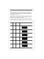
If your system requires a WORD length of 7 bits, one or two STOP
bits, and a PARITY check, select the appropriate option from Table 1.
Table 1. 7 Bit Options
Data
Stop
Bits
7
1
Odd
ED
7
1
Even
EC
7
1
Mark
EB
7
1
Space
EA*
7
2
Odd
EH
7
2
Even
EG
14
Parity
Option
User’s / Programming Guide
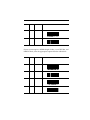
Table 1. 7 Bit Options
Data
Stop
Bits
7
2
Mark
EF
7
2
Space
EE
Parity
Option
If your system requires a WORD length of 8 bits, 1 or 2 STOP bits, and
PARITY check, select the appropriate option from the table below:
Table 2. 8 Bit Options
Data
Stop
Bits
8
1
Odd
EL
8
1
Even
EK
8
1
Mark
EJ
8
1
Space
EI
06656
Parity
Option
15
If your system requires a WORD length of 8 bits and 1 or 2 STOP bits,
but no PARITY, select the option below:
Table 3. 8 Bit, No Parity
8
1
8
2
None
EM
EN
PARITY check is not possible with this combination of STOP bits and
WORD length.
Some receiving equipment requires inverted serial communication
signals.
CD
Inverted Serial Communications
Communications Protocol
XON/XOFF
Protocol controls data flow between your PSC scanner and a serial
host computer. If Protocol = XON/XOFF is selected, the scanner recognizes the ASCII XON/XOFF characters. The host may then stop
transmission with XOFF and resume with XON.
Controlled data flow is achieved between devices when the receiving
device sends ASCII XON/XOFF codes to the transmitting device. In
other words, when the receiving device is unable to accept data, it
sends on XOFF code to inform the host to temporarily suspend data
transmission.
When the receiving device “catches up,” it sends an XON code to
inform the host that it is again ready to accept data. An advantage of
this protocol is that additional hardware is not required for implementation; only transmit, receive, and signal ground are required.
16
User’s / Programming Guide
CTS
Like XON/XOFF protocol, CTS protocol is a mechanism used to control data flow out. The CTS input is used to inform the scanner that
the host terminal is ready to accept scanned data. When CTS (+) protocol is selected, the scanner waits for a low level on its CTS input
before transmitting data. When CTS (-) is selected, the signal polarities are reversed and a high level indicates data may be transmitted.
The CTS protocol may be programmed independently of the RTS protocol; however, the signal polarities must be the same. You may not
select CTS (+) and RTS (-).
RTS
The RTS output from the scanner may be programmed to operate in
one of three different modes. In the default mode RTS signals when
the scanner is ready to receive commands or data. In the second
mode, RTS is in a fixed state. In the third mode, RTS signals when the
scanner has data to transmit. The RTS modes are independent of the
CTS protocol. However, you must select the same active state for RTS
as for CTS. You may not select CTS (-) and RTS fixed low. If CTS (-) is
selected, then the active state for RTS will be high.
The specified levels are at the modular connector and are
inverted when using an RS232 converter pod.
NOTE
HA
CTS Protocol = None*
RTS low indicates scanner ready to
receive data
HB
Protocol = XON/XOFF
HC
Protocol = CTS (-)
06656
17
HD
Protocol = CTS (+)
HG
RTS always low
HH
RTS always high
HI
RTS high indicates scanner ready
to receive data
HJ
RTS low indicates scanner has data
to transmit
HK
RTS high indicates scanner has
data to transmit
Another flow control option is available. If enabled, the stop/go protocol disables the trigger after every successful scan. The trigger is
then re-enabled with a serial ‘BG’ command in format
<STX><ESC>BG<ETX>.
BS
Disable Stop/Go Protocol*
BT
Enable Stop/Go Protocol
18
User’s / Programming Guide
Label Buffering
The user may select one of three levels of serial buffering. With Full
Buffering (the default) selected, the scanner will place all scanned
labels into a buffer for transmission. This allows the operator to continue scanning even though the previous label may not have been
transmitted yet. Scanning will continue normally until the buffer is
full, then scanning will stop. Scanning will continue when enough
space is available for the current label.
When No Buffering is selected then scanning will be stopped until
the current label is completely transmitted.
When One Label Buffering is selected the scanner will allow the operator to scan one more label in addition to the label already in the
transmit buffer. In other words, one label may be scanned beyond the
label being transmitted.
NE
Full Buffering
NF
No Buffering
NG
One Label Buffering
No Read Option
The scanner can be programmed to send a no read message (‘NR’)
upon a scan that does not result in a good read.
NX
Enable No Read
NY
Disable No Read *
06656
19
Menu Commands Parameter Messages
In serial mode, most menu commands when scanned will provide a
confirmation message to the host along with the ACK. This feature
can be enabled or disabled.
BA
Enable Parameter Messages *
BB
Disable Parameter Messages
External Trigger Operation
External trigger operation enables an external device to control scanning. External trigger is controlled by applying an external trigger
signal to the CTS input (with external triggering enabled). When
active, this signal causes scanning to begin just as if the scanner’s trigger were depressed. Scanning continue until a label is decoded or the
external trigger signal is deactivated.
In the event of a decode, the trigger signal must be deactivated for a
minimum of 50 milliseconds before another scan can be attempted
(“tying” the trigger signal active does not cause continuous scanning
and decoding).
When EXTERNAL TRIGGER(+) is scanned, scanning begins when a
high level input is applied to the CTS input. Conversely, when
EXTERNAL TRIGGER(-) is scanned, scanning begins when a low
level is applied to CTS. When CTS is not connected, it is treated as if a
high level is applied. The voltage levels given are at the modular connector. If an RS232 converter pod is used, then the levels are inverted.
HA
Disable External Trigger#*@
HE
External Trigger(+)
20
User’s / Programming Guide
HF
External Trigger(-)
General Parameters
Intercharacter Delay
Certain terminals and computers require an intercharacter delay to
simulate the effects of keystroke delays. Choosing an intercharacter
delay causes the characters to be sent at the slower speed required by
the device to which you are interfacing.
GA
No Intercharacter Delay
NOTE
GB
To set Intercharacter Delay to other then zero, scan the
label below and then scan two separate digits from the
Digit Selection page (99 maximum).
Intercharacter Delay = XXMEC
Intercharacter delay cannot exceed 99 milliseconds.
NOTE
Interlabel delay allows user to program a delay between transmitted
labels.
GC
No interlabel delay *@
GD
Set interlabel delay 0-9.9 seconds
06656
21
Transmission Mode
Full Duplex or Half Duplex
This section pertains only to models with a Liquid Crystal Display (LCD)
NOTE
Transmission mode selects either full or half duplex operation regardless of interface. In the half duplex mode, the decoded message is sent
simultaneously to the display and to the host computer. In the full
duplex mode, the message is sent to the host computer. In send mode,
the host always has the capability to send a message directly to the
LCD.
The advantage of the full duplex mode is that the display shows the
message received by the host. In the half duplex mode you can see
that the message has been sent but there is no confirmation that it was
received. The disadvantage of the full duplex mode is simply that the
host computer must be programmed to relay the message back to the
scanner.
NA
Transmission Mode = Full Duplex
NB
Transmission Mode = Half Duplex *#
For models which do not have an LCD, parameter selections NA and NB have no effect.
NOTE
System Status
To examine the configuration of your system, scan the appropriate
option.
When Option ZB is scanned, a list of currently programmed parameters is sent to the display device. Scanning ZB may interfere with your
terminal software, depending on your application.
22
User’s / Programming Guide
ZB
Display Configuration
When Option ZC is scanned, the program version followed by carriage return-line feed characters (CR-LF) is sent in the format
<software name>SP<###> (WDHB 3.86, for example).
ZC
Transmit Version Number
Power Consumption
You may choose one of two Power Consumption modes. Option @A
supplies full power to the scanner at all times; Option @B allows the
unit to revert to a standby mode after a successful read. This mode is
a power conservation feature.
@A
Enable Continuous@ Full Power
@B
Enable Standby *#
Laser Redundancy
For a successful decode to occur when Laser Redundancy is enabled,
two laser scans of the bar code must match. Because the laser scans a
label many times a second, you will notice little or no change in the
speed of the decode. Laser redundancy can be used to enhance the
security of the bar code reader.
BC
Disable Laser Redundancy *#@
BD
Enable 2 Times Laser Redundancy
06656
23
BE
Enable 4 Times Laser Redundancy
Laser Timeout
The scan beam will activate in response to a trigger pull. The beam
will automatically deactivate after a label is decoded. If a label is not
decoded., the scan beam will timeout and deactivate after several seconds. Scan the following labels to control the length of the timeout.
BH
Set Scan Beam *#@ Timeout
to 6 Seconds
BI
Set Scan Beam Timeout to 4
Seconds
BJ
Set Scan Beam Timeout to 2
Seconds
BO
Set Scan Beam Timeout to 1
Second
BW
Set Scan Beam Timeout to
½ Second
Beeper Operation
Scan one of the options below to modify beeper operation.
AA
Beeper Off
AB
Beeper On; Volume Low
24
User’s / Programming Guide
AC
Beeper On; Volume Medium
AD
Beeper On; Volume Loud *#@
Message Formatting
Message formatting describes how to format the data (decoded
string) that is sent from the scanner to the host.
The programmable options DO NOT apply in Wand Emulation.
NOTE
Prefixes and Suffixes
Prefix
Terminal ID
Preamble
Code ID
Data
Postamble
Suffix
Prefixes, Suffixes, Preambles and Postambles are programmable
attributes that are transmitted along with the decoded label data to
the host device. These attributes are handled differently whether the
scanner is configured for serial mode or wedge mode. When configured for wedge mode these attributes are sent as keystrokes. The
scanner automatically translates the ASCII characters into keystrokes
before sending data to the host. Refer to the keystroke translation
tables for non-printable ASCII characters.
06656
25
Prefix
A prefix is a subset of the preamble normally formatted to some
industry standard, i.e., it is represented by a specific ASCII code. An
example of a prefix is the STX (Start of Transmission) code.
IA
Prefix = None*#
IB
Prefix = STX
IC
Prefix = SOH
Suffix
A suffix is a subset of the Postamble. Like the prefix, it is normally
assigned a specific ASCII code. Examples of suffixes are CR (Carriage
Return) and LF (Line Feed).
MA
Suffix = None #
MB
Suffix = ETX
MC
Suffix = CR
MD
Suffix = LF
ME
Suffix = HT
26
User’s / Programming Guide
MF
Suffix = CR and LF *
Users also have the ability to select any ASCII character for use as a
suffix.
Scan the MJ label, then scan two labels from the Hexadecimal Conversion Table representing the character needed for the suffix.
MJ
Select Programmable
Suffix Character
Certain specialized applications require a two character suffix of ETB
NUL. Scanning MI provides this.
MI
Select Suffix = ETB NUL
Terminal ID
Terminal ID characters are used to identify individual scanners when
more than one scanner is interfaced with the host system. Options
available are none (DISABLED) or digits 01 through 99.
JA
ID Character = Disabled*#
If you scan the label below, you must also scan two of the
digits from the Digit Selection page.
NOTE
JB
06656
ID Character = XX
27
Code Identifier
A code identifier may optionally be transmitted with the message.
This option is provided so a host computer can identify the type of
bar code scanned, as well as the encoded information.
Scan Option FA to disable the code identifier.
FA
Disable Code ID # *
Scan Option FB to enable the code identifier.
FB
Enable Code ID
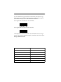
The table below shows the default code-identifier character assignments. These can be changed using the procedure found in the Symbology Identifier Section.
Table 4. Code Identifier Characters
SYMBOLOGY
CODE IDENTIFIER
Code 39
a
Code Interleaved 2 of 5
b
Code Standard 2 of 5
c
UPC/EAN/JAN
d
Code 128
f
Codabar
h
28
User’s / Programming Guide
Preamble or Postamble Selection
Preambles and Postambles are composed of up to four ASCII characters. Each ASCII character is encoded as two hexadecimal numbers.
Use the Hexadecimal Conversion Table in Appendix A to look up the
hexadecimal equivalent.
NOTE
If you select a Preamble or a Postamble you must scan
four ASCII characters, even if the Preamble or Postamble
is less than four characters in length. This is done by
scanning in null (NUL) characters for the additional characters. For example, if your Preamble is “AB” (in ASCII
code), scan A, then B, then two null characters, or 4,1, 4,2
0,0 0,0 hexadecimal.
Preamble
A Preamble is a string of characters that prefixes a message that is
transmitted to the host. The sequence and number of characters in a
Preamble is determined by the type of host system. Although not all
systems require a Preamble, those which do will only receive messages with the correct Preamble. The maximum preamble length is
four characters.
KA
Preamble = None*#
KB
Enter Preamble
IMPORTANT
Scan Enter Preamble to enter a Preamble, then refer to the Hexadecimal
Table in Appendix A.
Postamble
A Postamble is similar to a Preamble, except that it appended to the
message which is transmitted to the host. Its maximum length is also
four characters.
06656
29
LA
Postamble = None*#
LB
Enter Postamble
IMPORTANT
Scan Enter Postamble to enter a Postamble, then refer to the Hexadecimal
Table in Appendix A.
30
User’s / Programming Guide
Serial Commands
General Serial Command Format
Serial Commands are only accepted by the PSC scanner when in
serial communications mode.
Serial commands take the form: STX ESC LT1 LT2 <optional parameters>ETX (Note: STX = ^B; ETX = ^C)
STX, ESC, and ETX are ASCII codes whose values are 02H, 1BH, and
03H, respectively. LT1 and LT2 are uppercase ASCII letters (commercial A and @ are the same as those printed in earlier sections of this
manual under their corresponding menu bar code labels). The ESC
code that follows the STX code identifies this as a command. Some
commands require parameters such as minimum and maximum code
lengths, and strings of hexadecimal characters. When parameters are
required by the command, they immediately follow LT2. There are
never spaces within serial commands.
ACK/NAK
The scanner provides ACK/NAK protocol during serial programming in order to provide feedback to the host computer which is programming the scanner.
ACK/NAK protocol provides two vital functions. First, it provides
the host with positive acknowledgment that its commands are being
accepted and acted upon. Second, and perhaps more important, it
ensures that the host will not issue commands to the scanner more
quickly than the scanner can process them. For example, every time
the scanner receives a correct command, it modifies its internal
EEPROM, a function that takes about one second. At 9600 baud, the
host can easily issue commands to the scanner faster than they can be
processed. If after issuing each command the host waits to receive an
ACK or NAK code before issuing the next command, the scanner
cannot be overrun. If XON/XOFF or CTS/RTS Protocol is being used,
the scanner cannot be overrun by programming commands. However, the host is not provided with feedback as to the outcome of its
commands.
The ACK/NAK protocol is quite simple. Whenever the scanner
receives a correctly formatted command, it sends a confirmation message followed by an ACK (06H) code.
06656
31
Beeper Off CR-LF Ack
If the scanner receives an unknown or improperly formatted code, or
if the required parameters are missing or out-of-range, it sends a
NAK (15H) Code.
Command
Function
STX ESC PC ETX
Enable I 2 of 5 with check digit
STX ESC PD12 ETX
Set I 2 of 5 minimum length to 12
STX ESC PE14 ETX
Set I 2 of 5 maximum length to 12
STX ESC KB31323334 ETX
Set Preamble to ‘1234’
STX ESC LB61626364
Set Postamble to ‘abcd’
Serial Commands to Use with Caution
Some of the commands in this manual should not be used as serial
commands because of the consequences they produce. All PSC scanners use the same hardware components to implement both serial
communication and wand emulation. This means that all serial communication functions are disabled during wand emulation, and vice
versa. Because of this, issuing any of the commands in Table 5 causes
the scanner to enter its Wand Emulation mode, thereby disabling
serial communication.
CB
Wand Emulation, Code 39 Output
CC
Wand Emulation, Same Code Output
Furthermore, because the scanner acts upon a command and then
sends ACK or NAK, neither or these codes will be transmitted in
response to any of the above commands. In Table 5 only the command letters are listed; the complete command is prefixed with STX
ESC, and suffixed with ETX. Because it is not possible to set (via serial
command) two Wand Emulation parameters (emulation speed and
polarity, for example), scanners to be used in Wand Emulation environments must be programmed by scanning labels from this manual.
32
User’s / Programming Guide
Power Standby and Serial Commands
When the scanner is programmed for standby power operation (@B),
the first character of the command is used to “wake-up” the scanner;
it is not properly received by the scanner’s CPU. Therefore, when
there is any possibility that the scanner is in standby mode, an extra
space code should be transmitted before STX to ensure the scanner is
“awake” before sending commands to it. If the scanner is not being
operated in standby mode, the space has no effect on commands
(space prefixed commands are properly decoded). Having sent the
space code to “wake-up” the scanner, a 150 to 200 millisecond pause
must be observed to allow the scanner’s CPU to complete its initialization tasks, during which time it is unable to accept serial commands before issuing the programming command. Failure to observe
this delay causes the scanner to ignore the incoming command.
Communication Parameter Changes
All commands which affect serial communication are acted upon
immediately. Therefore, when changing communication parameters
(baud rate, word length, parity, etc.), the scanner will send the ACK
Code, using the newly implemented communication parameters.
There should be enough of a delay from the issuance of a communication parameter setup command for the properly programmed host
computer to modify its internal parameters and correctly receive the
ACK code sent by the scanner. This is due to the internal, one second
delay required for the scanner to update its internal EEPROM.
Manual Scanning Interaction
The decoder firmware makes no attempt to resolve conflicts between
serial programming commands and manually scanned menu labels.
If you plan to scan menu labels from the PSC Operator’s Manual, do
not attempt serial programming, and vice versa. Serial commands are
given priority over pending menu labels. For example, if you scan the
menu label SET I 2 of 5 MINIMUM LENGTH and the scanner is waiting for a two-digit, minimum length code when a serial command is
issued, the serial command is acted upon and the pending manual
command SET I 2 of 5 MINIMUM LENGTH is ignored.
06656
33
Keyboard Wedge Parameters
Scan symbol CE to enable Keyboard Wedge mode. Next, select a terminal type by scanning the symbol CF for IBM PC-AT or PS/2 models 50/60/80; or symbol CG for PC-XT type terminals. Alternatively,
you may scan just CF or CG to enable wedge mode and select a terminal type.
CE
Wedge Mode Enable @
ZA
Reset to Wedge Default
Values
CF
PC-AT, PS/2 and
50/60/80@ — U.S.A.
CG
PC-XT – U.S.A.
CH
IBM 3151 – U.S.A.
CI
DEC VT220 – U.S.A.
CN
Macintosh
CP
IBM 3477 – U.S.A.
34
User’s / Programming Guide
CT
IBM 319X – U.S.A.
CY
PS/2 Mode 57/25 — U.S.A.
C6
Unisys B-26
C8
Link 125
CV
PC-AT German Keyboard
CW
PC-AT French Keyboard
CX
PC-AT UK Keyboard
\B
PC-AT Belgian Keyboard
\C
PC-AT Swiss Keyboard
\D
PC-AT Danish Keyboard
06656
35
\E
PC-AT Italian Keyboard
\F
PC-AT Spanish Keyboard
\G
PC-AT Swedish Keyboard
\H
PC-AT Portuguese Keyboard
\L
DEC VT 220/320/420
German Keyboard
\M
DEC VT 220/320/420
French Keyboard
In normal Wedge Mode, the scanner emulates the keyboard exactly.
Should a scanned bar code label have alphabetic characters, they will
be presented to the computer as if they had been typed at the keyboard. They will be affected by the Caps Lock key. If the scanned
label has lower case alphabetic characters AND the Caps Lock key in
ON, then the alphabetics will be presented as upper case.
With the Caps Lock key ON, the user may required that the scanned
alphabetics are presented to the computer exactly as they are encoded
in the label. This is accomplished by scanning EO – Shift Alphabetic
Characters.
36
User’s / Programming Guide
EO
Shift Alphabetic Characters
EP
Normal Alphabetic Characters*
NOTE
In some models of scanner, the wedge output is capable
of two types. To enable primary or secondary keyboard
modes, scan one of the next two labels.
CQ
Enable Primary Keyboard@
CR
Enable Secondary Keyboard
NOTE
In Wedge Mode, non-printable ASCII characters (00-31H)
do not allow for an obvious translation to keycodes.
There are two approaches to this issue – they are
explained in Appendix A.
@Q
Enable Primary Function Key
Table@
@R
Enable Secondary Function Key
Table
See Appendix A.
NOTE
06656
37
Symbologies
The PSC scanner is configured with Code 39, Code 128, UPC-A and
UPC-E not expanded symbologies. The user has the ability to enable
or disable any of the symbologies given below as well as UPC or
EAN supplements, I 2 of 5 with check digit, and Code 39 modulo 43
check digit.
The bar codes that can be read by PSC’s bar code scanners include:
Code 39
Code 93
Interleaved 2 of 5
Code 128
Standard 2 of 5
Codabar
UPC-A, UPC-E
Code 11
EAN/JAN
MSI/Plessey
The minimum label lengths are set to 1 character, except Code I 2 of
5, which is set to 14 characters; andCode S 2 of 5, which is set to 4
characters. The maximum label length for all symbologies is set to 32
characters. The user has the ability to set the minimum and maximum label lengths.
The symbol * indicates Default Parameter for serial mode. The symbol # indicates Default Parameters for Wand Emulation. The symbol
@ indicates default parameters for Wedge Mode.
It is recommended that the user disable those symbologies and parameters that are not being used.
NOTE
UPC (A and E)
Scan Option QA to disable all UPC labels.
QA
38
Disable UPC (both A and E)
User’s / Programming Guide
Option QB or Option QC enable both UPC-A and UPC-E. If UPC is
enabled, any UPC label, with or without supplement, is read. The
supplement is read if Option QB is selected, and it is ignored if
Option QC is selected.
QB
Enable UPC with 2 or 5 Digit
Supplement Enabled
QC
Enable UPC with 2 or 5 Digit
Supplement Disabled *#@
Expanded UPC-E is disabled by scanning Option QH, or is enabled
by scanning Option QI.
QH
Disable Expanded UPC-E *#@
QI
Enable Expanded UPC-E
Transmission of the first character in a UPC symbol (the number system character) is disabled by scanning Option QD or enabled by
scanning Option QE.
QD
Disable Transmission of Number
System Digit
QE
Enable Transmission of Number
System Digit *#@
06656
39
Transmission of the last character in a UPC symbol (the check digit) is
disabled by scanning Option QF, or is enabled by scanning Option
QG.
QF
Disable Transmission of Check
Digit
QG
Enable Transmission of Check
Digit *#
Scanning QJ causes UPC-A labels to be transmitted as EAN-13
labels. Scanning QK disables this feature.
QJ
Enable UPC to EAN Translation
QK
Disable UPC to EAN Translation
*#@
QN
Disable second beep on
Supplement decoded *
QO
Enable second beep on
Supplement decoded
QP
Set supplement retry count (16 by
default) range = 1-32
QR
Disable transmissionof UPC-E
check digit
40
User’s / Programming Guide
QS
Enable transmissionof UPC-E
check digit*
QT
Disable transmission of UPC-E
number system digit
QU
Enable transmission of UPC-E
number system digit
QV
Disable UPC-E*
QW
Enable UPC-E independently with
supplement
QX
Enable UPC-E independently
without supplement*
Q0
Disable mandatory supplements*
Q1
Enable mandatory supplements
QA to QG apply to UPC-A and UPC-E.
NOTE
06656
41
EAN/JAN
Scan Option RA to disable EAN/JAN (8 or 13 digit).
RA
Disable EAN/JAN (8 or 13 Digit) #@
Option RB or RC enables both EAN 8 digit and EAN 13 digit. If
EAN/JAN is enabled, any EAN/JAN label, with or without supplement, is read. The supplement is read if Option RB is selected and is
ignored if Option RC is selected.
RB
Enable EAN/JAN with 2 or 5 Digit
Supplement enabled
RC
Enable EAN/JAN with 2 or 5 Digit
*Supplement disabled
Transmission of the first character in an EAN/JAN symbol (the number system character) is disabled by scanning Option RD, or is
enabled by scanning Option RE.
RD
Disable Transmission of Number
System Digit
RE
Enable Transmission of Number
System Digit *#@
42
User’s / Programming Guide
Transmission of the last character in an EAN/JAN symbol (the check
digit) is disabled by scanning Option RF, or is enabled by scanning
Option RG.
RF
Disable Transmission
of Check Digit
RG
Enable Transmission of
Check Digit *#@
RJ
Disable EAN-8 Transmission
of check character
RK
Enable EAN-8 Transmission
of check character*
RL
Disable EAN-8 Transmission of
number system digit
RM
Enable EAN-8 Transmission of
number system digit*
RN
Disable EAN-8 independently*
RO
Enable EAN-8 independently
with supplement
RP
Enable EAN-8 independently
without supplement
06656
43
RQ
Disable EAN-8 special 5 character
(0’s) preamble
RR
Enable EAN-8 special 5 character
(0’s) preamble
RA to RG apply to both EAN-13 and EAN-8.
NOTE
Code 39
To disable Code 39, scan Option OA.
OA
Disable Code 39
To enable Code 39, scan Option OB or OC. After enabling Code 39,
make any additional required selections from Options OD through
OG.
OB
Enable St6andard Code 39*#@
OC
Enable Full ASCII Code 39
OD
Disable Modulo 43 Check
Character*#@
OE
Enable Modulo 43 Check Character
44
User’s / Programming Guide
The minimum length of Code 39 messages is set by scanning Option
OH, followed by scanning two digits (01-32) from the Digit Selection
page.
OH
Minimum Length (specified by
two digits 01-32)
The maximum length of Code 39 messages is set by scanning Option
OI, followed by scanning two digits (01-32) from the Digit Selection
page. If the minimum and maximum values are set equal, only codes
of that exact length are read.
OI
Maximum Length (specified by
two digits 01-32)
The START and STOP characters in code 39 may either be transmitted
or suppressed. Scan Option OF to suppress transmission of the
START and STOP characters. Scan Option OG to enable transmission.
OF
Do Not XMIT START and STOP*#@
OG
Transmit START and STOP
The following are only valid if CHK CHAR is enabled.
OJ
Enable Transmission of Code 39
Modulo 43 Check Character
OK
Disable Transmission of Code 39
Modulo 43 Check Character *
06656
45
Code 2 of 5 – Interleaved
Scan Option PA to disable Interleaved Code 2 of 5.
PA
Disable Interleaved Code 2 of 5*#@
Scan Option PB or PC to enable Interleaved Code 2 of 5.
PB
Enable Interleaved 2 of 5 without
Check Digit
PC
Enable Interleaved 2 of 5 with
Check Digit
The minimum length of Interleaved 2 of 5 messages is set by scanning
Option PD, followed by scanning two digits (02-32) from the Digit
Selection page. The value of the number you scan must be even.
PD
Minimum Length I 2 of 5 (specified
by two digits 02-32)
The maximum length of Interleaved Code 2 of 5 is set by scanning
Option PE, followed by scanning two digits (02-32) from the Digit
Selection page. If the minimum and maximum values are set equal,
only codes of that exact length are read. The minimum and maximum
lengths must be even numbers.
PE
Maximum Length I 2 of 5 (specified
by two digits 02-32)
46
User’s / Programming Guide
Code 2 of 5 – Standard
Scan Option PF to disable Standard Code 2 of 5.
PF
Disable Standard Code 2 of 5 *#@
Scan Option PG to enable Standard Code 2 of 5.
PG
Enable Standard 2 of 5
The minimum length of Standard 2 of 5 messages is set by scanning
Option PH, followed by scanning two digits (01-32) from the Digit
Selection page.
The maximum length is set by scanning Option PI, followed by scanning two digits (01-32) from the Digit Selection page. If the minimum
and maximum values are set equal, only codes of that exact length are
read. The minimum and maximum lengths must be even numbers.
06656
47
Code 128
Scan Option TA to disable Code 128.
TA
Disable Code 128
Scan Option TB to enable Code 128.
TB
Enable Code 128 *#@
The minimum length of Code 128 messages is set by scanning Option
TC, followed by scanning two digits (01-32) from the Digit Selection
page.
TC
Minimum Length (specified by two
digits 01-32)
The maximum length of Code 128 messages is set by scanning Option
TD, followed by scanning two digits (01-32) from the Digit Selection
page. If the minimum and maximum values are set equal, only codes
of that exact length are read.
TD
Maximum Length (specified by two
digits 01-32) Codabar
Scan Option VA to disable Codabar.
VA
Disable Codabar *#@
Scan Option VB to enable Codabar.
VB
48
Enable Codabar
User’s / Programming Guide
The minimum length of Codabar messages is set by scanning Option
VE, followed by scanning two digits (01-32) from the Digit Selection
page.
VE
Minimum Length (specified by two
digits 01-32)
The maximum length of Codabar messages is set by scanning Option
VF, followed by scanning two digits (01-32) from the Digit Selection
page. If the minimum and maximum values are set equal, only codes
of that exact length are read.
VF
Maximum Length (specified by two
digits 0-32)
The transmission of the STOP/START Characters is enabled by scanning Option VD, or is suppressed by scanning Option VC.
VC
Disable Transmission *#@ of
START/STOP character
VD
Enable Transmission of START/
STOP Character
06656
49
MSI/Plessey
Previous customization of other scanner features may have made
MSI/Plessey unavailable in some scanners. Consult Customer Service for current capabilities or if you require a specific symbology.
PK
Enable MSI/PLESSEY
PL
Set Minimum Length, then scan
two digits: 01-14 (see Digit
Selection).
PM
Set Maximum Length, then scan
two digits: 01-14 (see Digit
Selection).
PJ
Disable MSI/PLESSEY
Code 11
Previous customization of other scanner features may have made
Code 11 unavailable in some scanners. Consult Customer Service for
current capabilities or if you require a specific symbology.
SB
Enable Code 11 with
one check digit
SC
Enable Code 11 with
two check digits
50
User’s / Programming Guide
SF
Set Minimum Length, specified by
two digits 01-32
SG
Set Maximum Length, specified by
two digits 01-32
SE
Enable transmission of check
digits
SD
Disable transmission of check
digits
SA
Disable Code 11
Code 93
Previous customization of other scanner features may have made
Code 93 unavailable in some scanners. Consult Customer Service for
current capabilities or if you require a specific symbology.
UB
Enable Code 93
UC
Standard Code 93
06656
51
UD
Enable Full ASCII Code 93
UE
Set Minimum Length, specified by
two digits 0-1-32
UA
Disable Code 93
16K
TF
Enable 16K Code
TE
Disable 16K Code
52
User’s / Programming Guide
Digit Selection
5
0
6
1
7
2
8
3
9
4
06656
53
Symbology Identifiers
Your PSC scanner can be programmed to add and/or change symbology identifiers which might be required to be transmitted with messages. This feature is provided to allow a host computer to recognize
the type of bar code scanned, as well as the uncoded information. The
symbology identifiers are selected by scanning the desired programming bar code symbol as defined below.
SYMBOL
FUNCTION
FA
Disable Transmission of
Symbology Identifiers*
FB
Enable Transmission of Symbology
Identifiers
FE
Set UPC-A Symbology Identifier
FF
Set UPC-E Symbology Identifier
FG
Set EAN-8 Symbology Identifier
FH
Set EAN-13 Symbology Identifier
FI
Set Code 128 Symbology Identifier
54
User’s / Programming Guide
FJ
Set Code 39 Symbology Identifier
FK
Set I 2/5 Symbology Identifier
FL
Set S 2/5 Symbology Identifier
FM
Set Code 11 Symbology Identifier
FN
Set Code 93 Symbology Identifier
FO
Set Codabar Symbology Identifier
FP
Set MSI/Plessey Symbology
Identifier
To change any single symbology identifier, scan the appropriate symbology identifier bar code symbol and then scan the four hexadecimal
characters that represent the two bytes of the identifier. If you select a
one character identifier, then scan zero (null) twice for the second
character.
06656
55
To find the hexadecimal values for the characters turn to the Hexadecimal Conversion Table. The procedure for selecting a symbology
identifier is identical to the procedure for selecting Preambles and
Postambles. The similar difference is that symbology identifiers are a
maximum of two characters, not four.
NOTE
Scanning the ZA (Result to Default) programming symbol
will set all symbology identifiers back to PSC defaults as
given in Table I and disable the transmission of the symbology identifiers.
The FC programming symbol selects the symbology identifiers for
use with ICL 9518/9520 cash registers.
FC
Programming Symbol
The FD programming symbol selects the symbology identifiers for
use with ICL 9518/9520 cash registers as given in Table 5.
FD
56
Programming Symbol
User’s / Programming Guide
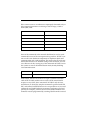
Table 5. Symbology Identifiers
ZA-PSC
Default
PC-ICL 9518
CCD
UPC-A
G
$
$
UPC-E
G
(
&
EAN-8
G
))
%
EAN-13
G
)
$
Code 128
I
,
<
Code 39
D
,
<
Interleaved 2/5
E
,
=
Standard 2/5
F
,
<
Code 11
H
,
<
Code 93
J
,
<
Codabar (NW7)
K
,
;
MSI/Plessey
S
,
<
Symbology
06656
57
Wand Emulation Parameters
Select Code Type
Scan Option CC if you intend to operate the scanner in Same Code
Wand Emulation mode. If you want the label to be transmitted in
Code 39 scan Option CB.
CC
Same Code Wand # Emulation
CB
Wand Emulation (Code 39, Full
ASCII)
Bar Code Polarity
Selected Option WA or WB.
WA
Black High#
WB
White High
WC
Black High, Quiescent High
Transmission Rate
Select the fastest speed your decoder will accept for best overall performance by scanning one of the following labels.
YA
58
5 inches per second
User’s / Programming Guide
YB
10 inches per second#
YC
15 inches per second
YD
20 inches per second
YE
30 inches per second
YF
50 inches per second
YG
70 inches per second
06656
59
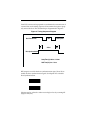
Data Synchronization
Your PSC scanner can be prepared to synchronize the transmission of
scanned data to the timing sequence some terminals require to properly receive the data. This relationship is diagrammed in Figure 2.
Figure 2. Timing Sequence Diagram
Data Transmission
data
(ta)
Active
white space
(th)
Data Synchronization
Setup Time (ts) 200 ms - 220 ms
Hold Time (th) 0 ms - 10 ms
RTS output is used for the data synchronization signal. Scan XD to
enable the data synchronization signal. Scan Option XC to disable
Data Synchronization.
XC
Disable Data # Synchronization
XD
Enable Data Synchronization
Polarity may be selected as either active high or low by scanning XE
(high) or XF (low).
60
User’s / Programming Guide
XE
Active # Polarity High
XF
Active Polarity Low
06656
61
Memory Module
The Memory Module option is a factory installed feature that is
requested at time of order. The Memory Module option allows the
5300 series scanner to store decoded labels in an internal battery
backed up RAM. The stored buffered labels can then be transmitted
some time later. The user may also choose an interlabel transmission
delay in cases where the transmission rate of the buffered decoded
label is faster than the receiving equipment.
Switching to the Memory Module mode is achieved by scanning the
Enable Memory Module symbol. The Memory Module is cleared
every time Memory Module is enabled. While in Memory Module
mode, the scanner will store in its internal memory all scanned bar
code labels.
The user can transmit the stored labels by scanning the Send Memory
Module symbol. When the transmission rate is faster than the receiving equipment, the user can program a delay that will occur after
each label. The delay is programmed by scanning the Interlabel Delay
symbol (see the Intercharacter Delay page of the Setup Parameters
section), followed by two digits (see Digit Selection page) to set the
delay duration. The allowable range of values is 00 to 99, where 99
corresponds to a delay of 9.9 seconds.
In order to restore the scanner to normal operation, the user needs to
scan the Disable Memory Module label. Also the user may clear the
contents of the Memory Module by scanning the Clear Memory Module symbol or by disabling and enabling Memory Module. Stored
labels are cleared whenever Memory Module is enabled.
The stored data in the Memory Module cannot be transmitted through the Wand Emulation output.
NOTE
CAUTION
62
The Memory Module feature is to be used only with the
Memory Module mode. When used with scanners without
this optional mode, programmed instructions will be
damaged.
User’s / Programming Guide
Setup
NC
Disable Memory Module*#
ND
Enable Memory Module
MM
Enable automatic switch to
memory module
MN
Disable automatic switch to
memory module *
If enabled, this mode intelligently switches from POS
mode to Memory Module mode based on power source.
NOTE
ZK
Send Memory Module
ZL
Clear Memory Module
06656
63
Marker Beam
The Marker Beam feature provides the user with a spotter beam for
improved aiming at distant bar code labels and/or in extremely
bright environments. You may also find a Marker Beam useful when
scanning through showcase glass or bar code menus with labels in
close proximity. This feature is available in all scanners without factory authorization.
To activate the Marker Beam, the user must also program the duration of the Marker Beam. First, the symbol Enable Marker Beam is
scanned and then followed by scanning one digit symbol from the
Digit Selections table. Each digit symbol represents the desired time
duration of the Marker Beam in milliseconds.
To deactivate the Marker Beam, the user must scan the Disable
Marker Beam symbol. For successful programming, the user must
hold the trigger down for two seconds after scanning.
NQ
Enable Marker Beam
NP
Disable Marker Beam
64
User’s / Programming Guide
300 ms
50 MS
350 MS
100 MS
400 MS
150 MS
450 MS
200 MS
500 MS
250 MS
06656
65
Scanner Labeling
The PSC Laser Scanners use a low-power, visible laser diode. As with
any bright light source, such as the sun, the user should avoid staring
directly into the light beam.
Use of controls, adjustments, or performance of procedures other than those specified herein may result in
hazardous visible light exposure.
WARNING
Service and Warranty
PSC provides service for its bar code products at the service center
located at its manufacturing facility in Eugene, Oregon. The specific
warranty language for the bar code scanner is contained in the next
section of this manual. Several service plans are available for the
products:
All products carry a minimum one year warranty from date of purchase.
•
A warranty extension program is available at a nominal
annual fee.
•
Factory service is available for out-of-warranty products
by requesting a Return Material Authorization (RMA)
for the product from our Repair Service Group. They can
be contacted by calling:
1-800-547-2507
within the continental United States, Canada, or Mexico)
or 1-541-683-5700 (elsewhere)
Should you call to request an RMA, have the following information
available:
•
Model Number
•
Serial Number
•
Date of Manufacture
•
Description of Problem
•
Purchase Order Number
The PSC Fax number is:
Fax: 541 686-1702
66
User’s / Programming Guide
Maintenance
PSC Scanners are designed to provide trouble-free operation
throughout their lives. They contain no components that require periodic maintenance. Optimum performance may be ensured by following the preventive maintenance procedures suggested below. If
scanning performance declines, please follow these procedures.
Cleaning
A dirty scan window can impair scanning performance. When the
window appears to be dirty or smeared, clean it by wiping with a
slightly damp cloth or facial tissue. Water or a suitable cleaning solution such as Windex™ may be used on the cloth. The plastic case of
your scanner can also be cleaned in this manner.
Never use solvents (e.g., alcohol) on the enclosure; they
may damage the finish of the scanner.
NOTE
Inspection
Periodically inspect scanner cords and cables for wear and other
signs of damage which may interfere with the proper operation of the
unit. A badly worn cord or cable should be replaced immediately.
Replacement cords and cables can be obtained by contacting your
PSC Customer Service Representative.
Routinely examine scanners for signs of damage. A badly dented
enclosure may cause interference with internal components resulting
in damage to, or malfunction of the unit. Units with damage to the
enclosure should be returned to the factory for repair. Please refer to
Service and Warranty Section.
06656
67
NOTES
68
User’s / Programming Guide
Appendix A
Hexadecimal Conversion Table
To use the conversion table:
1.
Find each ASCII character in the tables on the following
pages and locate the corresponding bold hexadecimal-equivalent character in the top row and in the left column of the
table. Notice, for example, that the ASCII character “Q” is
represented by the hexadecimal numbers 5 (top) and 1 (left).
2.
Scan the bar code symbols that correspond to the hexadecimal-equivalent characters. First scan the bar code symbol
that corresponds to the bold hex character at the top. Then
scan the bar code symbol that corresponds to the bold hex character
at the left.
For example, for the ASCII character “Q,” first scan the bar
code symbol labeled 5; then scan the bar code symbol labeled
1. If your preamble or postamble contains an “N”, first scan 4
and then E.
3.
06656
Repeat this procedure for each ASCII character you wish to
enter.
69
Hexadecimal Conversion Table
Part A
0
0
1
2
0
1
2
3
NUL
SOH
STX
ETX
DLE
DC1
DC2
DC3
SP
!
“
#
0
1
2
3
4
5
6
7
EOT
ENQ
ACK
BEL
DC4
NAK
SYN
ETB
$
%
&
‘
4
5
6
7
8
9
A
B
BS
HT
LF
VT
CAN
EM
SUB
ESC
(
)
*
++
8
9
:
;
C
D
E
F
FF
CR
SO
SI
FS
GS
RS
US
,
.
/
<
=
>
?
1
2
3
4
5
6
3
7
70
User’s / Programming Guide
Hexadecimal Conversion Table
Part B
8
4
5
6
7
0
1
2
3
@
A
B
C
P
Q
R
S
‘
a
b
c
p
q
r
s
4
5
6
7
D
E
F
G
T
U
V
W
d
e
f
g
t
u
v
w
8
9
A
B
H
I
J
K
X
Y
Z
[
h
i
j
k
x
y
z
{
C
D
E
F
L
M
N
O
\
]
^
_
l
m
n
o
|
}
~
DEL
9
A
B
C
D
E
F
06656
71
Primary Function Key Table
ASCII
NUL
SOH
STX
ETX
EOT
ENQ
ACK
BEL
BS
HT
LF
VT
FF
CR
SO
SI
DLE
DC1
DC2
DC3
DC4
NAK
SYN
ETB
CAN
EM
SUB
ESC
FS
GS
RS
US
72
HEX
00
01
02
03
04
05
06
07
08
09
0A
0B
0C
0D
0E
0F
10
11
12
13
14
15
16
17
18
19
1A
1B
1C
1D
1E
1F
FUNCTION
CONTROL@
CONTROL A
CONTROL B
CONTROL C
CONTROL D
CONTROL E
CONTROL F
CONTROL G
CONTROL H
CONTROL I
CONTROL J
CONTROL K
CONTROL L
RETURN KEY
CONTROL N
CONTROL O
CONTROL P
CONTROL Q
CONTROL R
CONTROL S
CONTROL T
CONTROL U
CONTROL V
CONTROL W
CONTROL X
CONTROL Y
CONTROL Z
CONTROL [
CONTROL \
CONTROL ]
CONTROL ^
CONTROL &
User’s / Programming Guide
Secondary Function Key Tables
PC/AT, PC/XT, IBM 3151, and IBM PS/2 Model 57/25
ASCII
NUL
SOH
STX
ETX
EOT
ENQ
ACK
BEL
BS
HT
LF
VT
FF
CR
SO
SI
DLE
DC1
DC2
DC3
DC4
NAK
SYN
ETB
CAN
EM
SUB
ESC
FS
GS
RS
US
HEX
00
01
02
03
04
05
06
07
08
09
0A
0B
0C
0D
0E
0F
10
11
12
13
14
15
16
17
18
19
1A
1B
1C
1D
1E
1F
FUNCTION
ESCAPE
NEW LINE ENTER
ALT left side Make
ALT left side Break
CTRL left side Make
CTRL left side Break
ENTER right keypad (NOTE 1)
Cursor up (inner keypad)
Cursor dn (inner keypad)
Cursor left (inner keypad)
Cursor right (inner keypad)
TAB FWD
DEL (inner keypad)
NEW LINE ENTER
INS (inner keypad)
Page Up (inner keypad)
Page Dn (inner keypad)
HOME (inner keypad)
PRINT SCREEN
BACKSPACE
BACKFIELD (Shift TAB)
SCROLL LOCK
F1
F2
F3
F4
F5
F6
F7
F8
F9
10
NOTE 1: [+] right keypad for the PC/XT and IBM PS/2 Model 57/25.
06656
73
Secondary Function Key Tables
IBM 3171/3181/3191 and IBM 3477
ASCII
NUL
SOH
STX
ETX
EOT
ENQ
ACK
BEL
BS
HT
LF
VT
FF
CR
SO
SI
DLE
DC1
DC2
DC3
DC4
NAK
SYN
ETB
CAN
EM
SUB
ESC
FS
GS
RS
US
74
HEX
00
01
02
03
04
05
06
07
08
09
0A
0B
0C
0D
0E
0F
10
11
12
13
14
15
16
17
18
19
1A
1B
1C
1D
1E
1F
FUNCTION
ESCAPE
ON LINE ENTER (Make/Break)
ALT left side Make
ALT left side Break
ON LINE ENTER (Make only)
FIELD EXIT (Make only)
ENTER right keypad
Cursor up (inner keypad)
Cursor dn (inner keypad)
Cursor left (inner keypad)
Cursor right (inner keypad)
TAB FWD
DEL (inner keypad)
FIELD EXIT (Make/Break)
INS (inner keypad)
Page Up (inner keypad)
Page Dn (inner keypad)
HOME (inner keypad)
PRINT SCREEN
BACKSPACE
BACKFIELD (Shift TAB)
SCROLL LOCK
F1
F2
F3
F4
F5
F6
F7
F8
F9
F10
User’s / Programming Guide
VT220/320/420
ASCII
HEX
NUL
00
SOH
STX
ETX
EOT
ENQ
ACK
BEL
BS
HT
LF
VT
FF
CR
SO
SI
DLE
DC1
DC2
DC3
DC4
NAK
SYN
ETB
CAN
EM
SUB
ESC
FS
GS
RS
US
01
02
03
04
05
06
07
08
09
0A
0B
0C
0D
0E
0F
10
11
12
13
14
15
16
17
18
19
1A
1B
1C
1D
1E
1F
06656
FUNCTION
‘~ (terminal may be configured for
ESCAPE)
NEW LINE ENTER – Return
ALT Make
ALT Break
CTRL Make
CTRL Break
ENTER – right side keypad
Cursor up
Cursor dn
Cursor left
Cursor right
TAB FWD
Remove
Return (Main keypad)
Insert Here
Prev
Next
PF1
PF2
BACKSPACE
PF3
PF4
F1
F2
F3
F4
F5
F6
F7
F8
F9
F10
75
Apple MacIntosh
ASCII
NUL
SOH
STX
ETX
EOT
ENQ
ACK
BEL
BS
HT
LF
VT
FF
CR
SO
SI
DLE
DC1
DC2
DC3
DC4
NAK
SYN
ETB
CAN
EM
SUB
ESC
FS
GS
RS
US
76
HEX
00
01
02
03
04
05
06
07
08
09
0A
0B
0C
0D
0E
0F
10
11
12
13
14
15
16
17
18
19
1A
1B
1C
1D
1E
1F
FUNCTION
NUL
F1
F2
F3
F4
F5
F6
F7
F8
TAB
Enter
Page Up
Page Down
RETURN
F9
F10
Command On
Delete
Command Off
Left Arrow
Right Arrow
Down Arrow
Up Arrow
Home
End
Shift On
Shift Off
Esc
Control On
Control Off
Option (Alt) On
Option (Alt) Off
User’s / Programming Guide
DECLARATION OF CONFORMITY
PSC hereby declares that the Equipment specified below has
been tested and found compliant to the following Directives
and Standards:
Directives:
EMC
Low Voltage
Standards:
EN
EN 50082-1
EN 60950
Equipment Type:
Product:
Handheld Laser
Bar Code Scanners
Keyboard Wedge/
Wand Emulation Interface
Charles W. Vanlue
Director, Corporate Quality
PSC, Inc.
959 Terry Street
Eugene, OR 97402
U.S.A.
Nigel Davis
Vice President
Europe, Middle East & Africa
PSC Bar Code Ltd.
Axis 3, Rhodes Way
Watford, England
WD24YW
UK
Part No. 06656• Rev C (03/00)
Asia Pacific
Italy
PSC Hong Kong
Hong Kong
Telephone: [852]-2-584-6210
Fax: [852]-2-521-0291
PSC S.r.l.
Vimercate (MI), Italy
Telephone: [39] (0) 39/62903.1
Fax: [39] (0) 39/685496
Australia
Japan
PSC Asia Pacific Pty Ltd.
North Ryde, Australia
Telephone: [61] 0 (2) 9878 8999
Fax: [61] 0 (2) 9878 8688
PSC Japan K.K.
Shinagawa-ku, Tokyo, Japan
Telephone: 81 (0)3 3491 6761
Fax: 81 (0)3 3491 6656
France
Latin America
PSC Sarl
LES ULIS Cedex, France
Telephone: [33].01.64.86.71.00
Fax: [33].01.64 46.72.44
PSC S.A., INC.
Miami, Florida, USA
Telephone: (305) 539-0111
Fax: (305) 539-0206
Germany
United Kingdom
PSC GmbH
Darmstadt, Germany
Telephone: + 49 (0) 61 51/93 58-0
Fax: + 49 (0) 61 51/93 58 58
PSC Bar Code Ltd.
Watford, England
Telephone: 44 (0) 1923 809500
Fax: 44 (0) 1923 809 505
Corporate Headquarters
675 Basket Road
Webster, NY 14580-9787
Telephone: (716) 265-1600
Toll Free: (800) 828-6489
Fax: (716) 265-6400
PSC Scanning, Inc.
www.pscnet.com
959 Terry Street
Eugene, OR 97402-9150
Telephone: (541) 683-5700
Toll Free: (800) 547-2507
Fax: (541) 686-1702
PRINTED WITH
SOY INK
Printed on recycled paper
©2000 PSC INC.
06656 (Rev C)
Printed in USA (03/00)