1
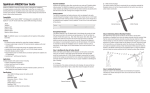
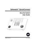
USER
MANUAL
Model 2192/USB/V.92
USB Modem
Part# 07M2192 Rev. A
Doc# 09401U2-001
Revised 10/26/04
An ISO-9001
Certified Company
SALES OFFICE
+1 (301) 975-1000
TECHNICAL SUPPORT
+1 (301) 975-1007
www.patton.com
CONTENTS
1.0
1.1
1.2
1.3
Compliance and Trademarks.....................................................
FCC Notice ...................................................................................
FCC Requirement.........................................................................
Trademark Acknowledgements ....................................................
3
3
3
4
2.0
2.1
2.2
General Information....................................................................
Package Contents ........................................................................
V.92 Features ...............................................................................
QuickConnect ...............................................................................
PCM Upstream .............................................................................
Modem-on-Hold (MOH) ................................................................
V.44 Data Compression ...............................................................
5
5
5
6
6
6
6
3.0
3.1
3.2
3.3
3.4
Installation................................................................................... 7
Setting Up the Modem in Windows 98.......................................... 7
Setting Up the Modem in Windows ME ...................................... 11
Setting Up the Modem in Windows 2000.................................... 12
Setting Up the Modem in Windows XP....................................... 13
4.0
4.1
Setting Up and Using Modem-on-Hold ...................................
Configuring Modem-on-Hold.......................................................
Configuring V.92 settings ...........................................................
Selecting the country/area..........................................................
Enabling the speaker (optional)..................................................
Connecting and logging onto your ISP .......................................
Using Modem-on-Hold................................................................
Making an outgoing call while online ..........................................
Receiving a call while online.......................................................
4.2
4.3
5.0
5.1
5.2
16
16
16
18
19
20
20
21
22
Diagnostics ............................................................................... 25
Windows 98/ME.......................................................................... 25
Windows 2000/XP ...................................................................... 25
2
1.0 COMPLIANCE AND TRADEMARKS
1.1 FCC NOTICE
This equipment has been tested and found to comply with the limits for a
Class B digital device, pursuant to Part 15 of FCC Rules. These limits are
designed to provide reasonable protection against harmful interference
in a residential installation. This equipment generates, uses and can radiate radio frequency energy and, if not installed and used in accordance
with the instructions, may cause harmful interference to radio communications. However, there is no guarantee that interference will not occur in
a particular installation. If this equipment does cause harmful interference to radio or television reception, which can be determined by turning
the equipment off and on, the user is encouraged to try to correct the
interference by one or more of the following measures:
• Reorient of relocate the receiving antenna.
• Increase the separation between the equipment and receiver.
• Connect the equipment into an outlet on a circuit different from that to
which the receiver is connected.
• Consult the dealer or an experienced radio / TV technician for help.
This unit was tested with shielded cables on the peripheral devices.
Shielded cables must be used with the unit to insure compliance. This
statement can be deleted if unit was not tested with shielded cables.
The manufacture is not responsible for any radio or TV interference
caused by unauthorized modifications to this equipment. Such modifications could void the user's authority to operate the equipment.
This device complies with Part 15 of the FCC rules. Operation is subject
to the following two conditions:
• This device may not cause harmful interference.
• This device must accept any interference that may cause undesired
operation.
1.2 FCC REQUIREMENT
This equipment complies with Part 68 of the FCC Rules. On the base
unit of this equipment is a label that contains, among other information,
the FCC Registration Number and Ringer Equivalence Number (REN)
for this equipment. If requested, this information must be given to Telephone Company.
3
The REN is useful in determining the quantity of devices you may connect to your telephone line and still have those entire devices ring when
your telephone number is called. In most, but not all area, the sum of the
RENs of all devices connected to one line should not exceed five (5). To
be certain of the number of devices you may connect to your line, as
determined by the REN, you should contact your local telephone company to determine the maximum REN for your calling area.
If your equipment causes harm to the telephone network, the telephone
company may discontinue your service temporarily. If possible, they will
notify you in advance. But if advance notice is not practical, you will be
notified as soon as possible. You will be informed of your right to file a
complain with the FCC. Your telephone company may make changes in
its facilities, equipment, operations or procedures that could affect the
proper functioning of your equipment. If they do, you will be notified in
advance to give you an opportunity to maintain uninterrupted telephone
service.
The telephone company may not use the equipment on coin service.
Connection to party lines is subject to state tariffs.
1.3 TRADEMARK ACKNOWLEDGEMENTS
The terms Microsoft, Windows 98, Windows 2000, Windows ME, and
Windows XP are registered trademarks of Microsoft Corporation in the
United States and other countries. The term Linux is a registered trademark of Linus Torvalds.
4
2.0 GENERAL INFORMATION
Congratulations on your purchase of this USB Modem. The Model
2192/USB/V.92 Modem features the latest innovations in high speed
modem design to make electronic communication faster and easier,
including V.92 compatibility. This manual will show you how to install and
properly use the modem in order to take full advantage of its features. If
any questions or problems arise during installation or use of this product,
contact Patton Electronics Technical Support at +1 (301) 975-1007.
Note
Follow all cautions and instructions in this manual to avoid damaging the product.
2.1 PACKAGE CONTENTS
Carefully unpack and remove the carton contents. Contact your dealer
immediately if any of the following items are missing or damaged:
Model 2192/USB/V.92 Modem
Modem carton
CD-ROM (contains modem
driver software and user manual)
RJ-11 telephone cable
USB
cable
2.2 V.92 FEATURES
The Patton 2192 USB modem is compatible with the V.92 modem standard and, when operated in conjunction with services provided by your
local phone company and Internet service provider (ISP), provides the
following capabilities:*
• QuickConnect
• PCM Upstream
*
Your ISP and local phone company must support V.92. If they do, the
USB modem will automatically detect that it can use V.92.
5
• Modem-on-Hold
• V.44 Data Compression
QuickConnect
Allows your modem to connect to the ISP faster than before. Very simply,
QuickConnect shortens the time it takes to make a connection by
remembering the phone line and ISP characteristics, then storing them
for later usage. QuickConnect cuts the modem handshake time in half for
most calls.
PCM Upstream
Boosts the upstream data rates between you and your ISP to reduce
upload times for large files and email attachments. Although previous
modem standards like V.90 may have shown a downstream connection
rate of up to 57.6 the actual upload speeds were limited to 33.6 kbps.
V.92 raises the upload rate to a maximum of 48 kbps so e-mails and file
transfers can upload much faster.
Modem-on-Hold (MOH)
Many households use the same phone line for voice calls and for surfing
the Internet. Before MOH, the user browsing the Internet prevented
incoming or outgoing phone calls. Now, modem-on-hold enables users to
receive incoming calls while remaining connected to the Internet.** Also,
you can make a voice call while connected to the Internet and keep the
modem connection active. Typically, you can spend up to 10 minutes on
a voice call without affecting your online connection, then, when you
hang up the phone, you can resume browsing. For more information on
using modem-on-hold, go to Section 4.0, “Setting Up and Using Modemon-Hold” on page 16.
V.44 Data Compression
Automatically compresses your data to boost your effective data delivery
rates from 10 to 120% faster than those achieved by using the V.42bis compression protocol. The most popular activity on the Internet is browsing web
sites, and this is where V.44 delivers the greatest improvement over V.42bis.
Most web pages use HTML content that can be highly compressed to
increase your data throughput by up to 120%. V.44 increases data throughput for email by up to 27%, Word documents by up to 21%, PowerPoint files
by up to 10%, and C source files by up to 45%. V.44 will not typically
increase your data delivery rate for already compressed files like JPEG and
GIF pictures, and TAR, SIT, and ZIP archived software downloads.
** Call-Waiting service from your phone company is required.
6
3.0 INSTALLATION
This chapter contains the following sections that describe installing the
modem driver software:
• Section 3.1, “Setting Up the Modem in Windows 98” on page 7
• Section 3.2, “Setting Up the Modem in Windows ME” on page 11
• Section , “Congratulations! The modem is installed.” on page 12
• Section , “Congratulations! The modem is installed.” on page 13
3.1 SETTING UP THE MODEM IN WINDOWS 98
This section describes how to install your Model 2192 USB modem in
Windows. When installed, the installation should look like the diagram
shown in Figure 1.
Note
The connection diagram in Figure 1 includes an optional RJ-11
modular T adapter so the USB modem and a telephone can
share the same telephone wall jack. If you will not be sharing the
wall jack, it is not necessary to install a T adapter.
Figure 1. Connection diagram
7
1. Insert the CD into your CD-ROM and the system will execute the
setup.exe automatically. The Modem Installation window (see
Figure 2) will appear. Click
to begin installing the modem
driver.
Figure 2. Modem Installation window
2. When the Setup Complete message displays (see Figure 3),
Click
.
Figure 3. Modem Installation window—Setup Complete
8
3. Connect one end of the USB cable supplied with the modem to the
USB port on the modem (see Figure 4).
Figure 4. USB port location
4. Connect the other end of the cable to one of the PC’s USB ports.
The port is usually labeled with the symbol shown in Figure 5.
Figure 5. USB symbol
9
5. Plug one end of the RJ-11 cable supplied with the modem into the
RJ-11 jack (see Figure 6).
Figure 6. RJ-11 port location
6. Plug the other end of the RJ-11 cable into the modular jack on the
wall outlet or optional T adapter.
7. Verify that the red POWER LED on the modem (see Figure 7) is lit.
Figure 7. Model 2192 LEDs
10
8. Windows 98 detects the USB modem automatically and displays
the message Add New Hardware Wizard, click Next to continue
(see Figure 8).
Figure 8. Add New Hardware Wizard window
Congratulations! The modem is installed.
3.2 SETTING UP THE MODEM IN WINDOWS ME
This section describes how to install your Model 2192 USB modem in
Windows. When installed, the installation should look like the diagram
shown in Figure 1 on page 7.
Note
The connection diagram in Figure 1 on page 7 includes an
optional RJ-11 modular T adapter so the USB modem and a
telephone can share the same telephone wall jack. If you will not
be sharing the wall jack, it is not necessary to install a T adapter.
1. Insert the CD into your CD-ROM and the system will execute the
setup.exe automatically. The Modem Installation window (see
Figure 2 on page 8) will appear. Click
to begin installing the
modem driver.
2. When the Setup Complete message displays (see Figure 3 on
page 8), Click
.
3. Connect one end of the USB cable supplied with the modem to the
USB port on the modem (see Figure 4 on page 9).
4. Connect the other end of the cable to one of the PC’s USB ports.
The port is usually labeled with the symbol shown in Figure 5 on
page 9.
11
5. Plug one end of the RJ-11 cable supplied with the modem into the
RJ-11 jack (see Figure 6 on page 10).
6. Plug the other end of the RJ-11 cable into the modular jack on the
wall outlet or optional T adapter.
7. Verify that the red POWER LED on the modem (see Figure 7 on
page 10) is lit.
8. Windows ME detects the USB modem automatically and displays
the message Found New Hardware Wizard”, click Next to continue
(see Figure 9).
Figure 9. Add New Hardware Wizard window
Congratulations! The modem is installed.
3.3 SETTING UP THE MODEM IN WINDOWS 2000
This section describes how to install your Model 2192 USB modem in
Windows. When installed, the installation should look like the diagram
shown in Figure 1 on page 7.
Note
The connection diagram in Figure 1 on page 7 includes an
optional RJ-11 modular T adapter so the USB modem and a
telephone can share the same telephone wall jack. If you will not
be sharing the wall jack, it is not necessary to install a T adapter.
1. Connect one end of the USB cable supplied with the modem to the
USB port on the modem (see Figure 4 on page 9).
2. Connect the other end of the cable to one of the PC’s USB ports.
The port is usually labeled with the symbol shown in Figure 5 on
page 9.
12
3. Plug one end of the RJ-11 cable supplied with the modem into the
RJ-11 jack (see Figure 6 on page 10).
4. Plug the other end of the RJ-11 cable into the modular jack on the
wall outlet or optional T adapter.
5. Verify that the red POWER LED on the modem (see Figure 7 on
page 10) is lit.
6. Windows 2000 detects the USB modem automatically and displays
the message Found New Hardware Wizard”, click Cancel to continue (see Figure 10).
Figure 10. Found New Hardware Wizard
7. Insert the CD into your CD-ROM and the system will execute the
setup.exe automatically. The Modem Installation window (see
Figure 2 on page 8) will appear. Click
to begin installing the
modem driver.
8. When the Setup Complete message displays (see Figure 3 on
page 8), Click
.
Congratulations! The modem is installed.
3.4 SETTING UP THE MODEM IN WINDOWS XP
This section describes how to install your Model 2192 USB modem in
Windows. When installed, the installation should look like the diagram
shown in Figure 1 on page 7.
13
Note
The connection diagram in Figure 1 on page 7 includes an
optional RJ-11 modular T adapter so the USB modem and a
telephone can share the same telephone wall jack. If you will not
be sharing the wall jack, it is not necessary to install a T adapter.
1. Connect one end of the USB cable supplied with the modem to the
USB port on the modem (see Figure 4 on page 9).
2. Connect the other end of the cable to one of the PC’s USB ports.
The port is usually labeled with the symbol shown in Figure 5 on
page 9.
3. Plug one end of the RJ-11 cable supplied with the modem into the
RJ-11 jack (see Figure 6 on page 10).
4. Plug the other end of the RJ-11 cable into the modular jack on the
wall outlet or optional T adapter.
5. Verify that the red POWER LED on the modem (see Figure 7 on
page 10) is lit.
6. Windows XP detects the USB modem automatically and displays
the message Found New Hardware Wizard”, click Cancel to continue (see Figure 10).
Figure 11. Found New Hardware Wizard
14
7. Insert the CD into your CD-ROM and the system will execute the
setup.exe automatically. The Modem Installation window (see
Figure 2 on page 8) will appear. Click
to begin installing the
modem driver.
8. When the Setup Complete message displays (see Figure 3 on
page 8), Click
.
Congratulations! The modem is installed.
15
4.0 SETTING UP AND USING MODEM-ON-HOLD
The modem-on-hold feature requires the following:
• Internet service from an ISP that supports V.92—Verify that your ISP
supports V.92 MOH. Be sure to ask how long an Internet call can be
left on hold before your Internet session will be disconnected.
• Extra services from your local phone company—Check with your local
phone company to see if your telephone line has these features:
– The ability to receive voice calls while on a data call—You must have
call waiting service from your local phone company. Call waiting
(your local phone company may have a different name for the service) enables you to receive a second phone call while your phone
line is already in use (or off-hook).
– The ability to make voice calls while on a data call—You may be
required to have 3-way calling (It may be called another name by your
local phone company) which enables you to make a second phone
call while your phone line is already off hook. For voice calls you can
switch to the second phone call by using flash hook (i.e., pressing and
releasing the flash hook button quickly to signal to the exchange to put
the current call on hold).
• The connections between your PC, the modems and phones within
the premise—The USB modem is essentially like connecting another
phone handset to your existing telephone wiring.
The following sections describe setting up and using MOH.
4.1 CONFIGURING MODEM-ON-HOLD
Configuring V.92 settings
1. Left mouse click on Start > Settings > Control Panel > V.92 features
settings (see Figure 12).
Figure 12. Selecting the V.92 features settings panel
16
The SmartUSB56 Voice Modem Properties control panel displays
(see Figure 13).
Figure 13. V.92 Features panel
2. Click the Modem on Hold tab (see Figure 13). Verify that the Enable
Incoming Modem on Hold box is checked (see Figure 14).
Figure 14. Modem on Hold panel
17
3. Select what you want the modem to do when a phone call is
received while you’re online (see Figure 14 on page 17).
4. Click the OK button to save changes and close the control panel.
Selecting the country/area
1. Left mouse click on Start > Settings > Control Panel > Modem Settings (see Figure 15).
Figure 15. Selecting the Modem Settings panel
2. Click on the Configuration tab to bring it to the front of the panel.
18
3. Select the country or area where the 2192 Modem is installed by
selecting from the Country/Area pop-up menu (see Figure 16).
Figure 16. Configuration panel
Enabling the speaker (optional)
1. Click on the Speaker tab (see Figure 17). You can choose to enable
your PC speakers to play sounds representing activities of the
modem. The modem will play modem connection tones during the
connection process and, while using modem on hold, will play a
ringing sound upon the arrival of a call.
Figure 17. Speaker panel
19
2. Click on the Soft Speaker > Enabled box so a check mark appears.
3. Move the speaker volume slider (see Figure 17 on page 19) to
the desired setting.
4.2 CONNECTING AND LOGGING ONTO YOUR ISP
Connect to your ISP as usual. After connecting, you will see an
icon in
the system tray (see Figure 18), indicating that the modem is online.
Figure 18. System tray
4.3 USING MODEM-ON-HOLD
You have the following options when using the modem-on-hold feature:
• Making an outgoing call while online (see section “Making an outgoing
call while online” on page 21 for details)
• Receiving a call while online (see section “Receiving a call while
online” on page 22 for details)
20
Making an outgoing call while online
1. To make an outgoing call while online, click on the
icon in the
system tray, the SmartUSB56 Voice Modem panel displays (see
Figure 19)
Figure 19. SmartUSB56 Voice Modem panel
2. Select the Modem On Hold tab (see Figure 19).
3. Click on the Make a Phone Call button (see Figure 19).
Figure 20. Making a phone call window
4. Your Internet connection is temporarily suspended when the Making a phone call window displays (see Figure 20).
You may then pick up a telephone handset and make your voice call.
To be able to reconnect to your suspended Internet connection, your
voice call must complete before the timer expires.
21
Note
Your ISP controls how long the Internet connection can be
on hold.
5. When your call is complete, click on the Resume my Internet Connection button (see Figure 20 on page 21). While your Internet
connection is resuming, you will see the Resuming Your Internet
Connection window (see Figure 21).
Figure 21. Resuming Your Internet Connection window
Note
If you do not finish your call before the timer expires, your voice
call will automatically be disconnected and you may also lose your
Internet connection. To avoid this, there are two workarounds:
• Ask the person to whom you are speaking to hang up before
the timer expires and call you back in a minute. Then resume
your Internet connection until the caller contacts you again,
this way the conversation can continue on indefinitely,
although in segments.
• Make arrangements with the person to whom you are speaking to continue the call later and hang up, resume your Internet connection, disconnect from the Internet, then take the
call as usual.
Receiving a call while online
1. Connect and log into your ISP (see section “Connecting and logging onto your ISP” on page 20).
2. If you have set Modem On Hold in the V.92 features settings control
panel to Ask me whether to accept calls, a pop-up screen will display if an incoming call arrives while you are on your Internet con-
22
nection (see Figure 22). You will also hear a ringing sound if you
have configured the Modem Settings control panel to have Soft
Speaker enabled.
Figure 22. Receiving Phone Call window
3. If you choose to answer the call, the Receiving Phone Call window
changes to show the Remaining hold time timer (see Figure 23).
Figure 23. Receiving Phone Call window with Remaining hold time timer
You now can pick up a telephone handset and start your conversation.
Note
The telephone handset will not ring.
To be able to reconnect to your suspended Internet connection, your
voice call must complete before the timer expires.
Note
Your ISP controls how long the Internet connection can be
on hold.
4. When your call is complete, click on the Resume my Internet Connection button (see Figure 23). While your Internet connection is
resuming, you will see the Resuming Your Internet Connection window (see Figure 21 on page 22).
23
Note
If you do not finish your call before the timer expires, your voice
call will automatically be disconnected and you may also lose your
Internet connection. To avoid this, there are two workarounds:
• Ask the person to whom you are speaking to hang up before
the timer expires and call you back in a minute. Then resume
your Internet connection until the caller contacts you again,
this way the conversation can continue on indefinitely,
although in segments.
• Make arrangements with the person to whom you are speaking to continue the call later and hang up, resume your Internet connection, disconnect from the Internet, then take the
call as usual.
24
5.0 DIAGNOSTICS
5.1 WINDOWS 98/ME
1. Select Start > Settings >Control Panels. Then double-click on the
Modems icon.
2. Click on the Diagnostics tab.
3. Select the COM Port that the modem is using and click on the More
Info… button to start the test.
4. If your modem is responding to AT commands correctly, it means
that your modem is working properly. Click OK to exit from diagnostics testing.
5.2 WINDOWS 2000/XP
1. Select Start > Settings > Control Panels. Then double-click on the
Phone and Modem Options icon.
2. Click on the Modems tab
3. Select your USB modem, then click Properties.
4. Click on the Diagnostics tab.
5. Click Query Modem.
6. If your modem is responding to AT commands correctly, it means
that your modem is working properly. Click OK to exit from diagnostics testing.
25
Notes
_________________________________________________________
_________________________________________________________
_________________________________________________________
_________________________________________________________
_________________________________________________________
_________________________________________________________
_________________________________________________________
_________________________________________________________
_________________________________________________________
_________________________________________________________
_________________________________________________________
_________________________________________________________
_________________________________________________________
_________________________________________________________
_________________________________________________________
_________________________________________________________
_________________________________________________________
_________________________________________________________
_________________________________________________________
_________________________________________________________
_________________________________________________________
_________________________________________________________
_________________________________________________________
_________________________________________________________
26
Notes
_________________________________________________________
_________________________________________________________
_________________________________________________________
_________________________________________________________
_________________________________________________________
_________________________________________________________
_________________________________________________________
_________________________________________________________
_________________________________________________________
_________________________________________________________
_________________________________________________________
_________________________________________________________
_________________________________________________________
_________________________________________________________
_________________________________________________________
_________________________________________________________
_________________________________________________________
_________________________________________________________
_________________________________________________________
_________________________________________________________
_________________________________________________________
_________________________________________________________
_________________________________________________________
_________________________________________________________
27
Notes
_________________________________________________________
_________________________________________________________
_________________________________________________________
_________________________________________________________
_________________________________________________________
_________________________________________________________
_________________________________________________________
_________________________________________________________
_________________________________________________________
_________________________________________________________
_________________________________________________________
_________________________________________________________
_________________________________________________________
_________________________________________________________
_________________________________________________________
_________________________________________________________
_________________________________________________________
_________________________________________________________
_________________________________________________________
_________________________________________________________
_________________________________________________________
Copyright © 2004
Patton Electronics Company
All Rights Reserved.
28