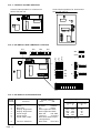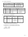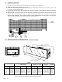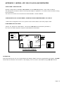
1
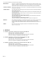
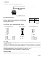
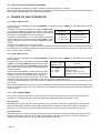
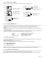
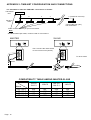
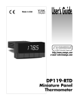
User's Guide http://www.omega.com e-mail: info @omega.com LDP-124, LDP-126, LDP-144 AND LDP-146 OPERATOR´S MANUAL FOR CLOCK MODELS OMEGAnet On-Line Service http://www.omega.com Internet e-mail [email protected] Servicing North America: USA : ISO 9001 Certified Canada : One Omega drive, Box 4047 Stamford, CT 06907-0047 Tel : (203) 359-1660 e-mail : [email protected] 976 Bergar Laval (Quebec) H7L 5A1 Tel : (514) 856-6928 e-mail : [email protected] Fax : (203) 359 7700 Fax : (514) 856-6886 For immediate technical or application assistance: USA and Canada : Mexico and Latin America : Sales Service : 1-800-826-6342 / 1-800-TC-OMEGASM Customer Service : 1-800-622-2378 / 1-800-622-BESTSM Engineering Service : 1-800-872-9436 / 1-800-USA-WHENSM Telex : 996404 EASYLINK : 62968934 CABLE : OMEGA Tel : (95) 800-826-6342 En Español : (203) 359-7803 Fax : (95) 203-359-7807 e-mail : [email protected] Servicing Europe: Benelux: Czech Republic : France : Germany/Austria : United Kingdom : ISO 9002 Certified Postbus 8034, 1180 LA Amstelveen, The Netherlands Tel : (31) 20 6418405 Fax : (31) 20 6434643 Toll Free in Benelux : 0800 0993344 e-mail : [email protected] ul. Rude armady 1868, 733 01 Karvina-Hranice Tel : 420 (69) 6311899 Fax : 420 (69) 6311114 Toll Free : 0800-1-66342 e-mail : [email protected] 9, rue Denis Pappin, 78190 Trappes Tel : (33) 130-621-400 Fax : (33) 130-699-120 Toll Free in France : 0800-4-06342 e-mail : [email protected] Daimlerstrasse 26, D-75392 Deckenpfronn, Germany tel : 49 (07056) 3017 Fax : 49 (07056) 8540 Toll Free in Germany : 0130 11 21 66 e-mail : [email protected] One Omega Drive, River Bend Thecnology Centre Northbank, Irlam, Manchester M44 5EX, England Tel : 44 (161) 777-6611 Fax : 44 (161) 777-6622 Toll Free in the United Kingdom : 0800-488-488 e-mail : [email protected] It is the policy of OMEGA to comply with all worldwide safety and EMC/EMI regulations that apply. OMEGA is constantly pursuing certification of its products to the European New Approach Directives. OMEGA will add the CE mark to every appropriate device upon certification. The information contained in this document is believed to be correct, but OMEGA Engineering, Inc. accepts no liability for any errors it contains, and reserves the right to alter specifications without notice. WARNING : These products are not designed for use in, and should not be user for, patient connected applications. Page :1 CONTENTS DESCRIPTION SECTION PAGE =========================================================================== IMPORTANT SAFETY CONSIDERATIONS 1 3 UNPACKING AND INSPECTION 2 4 MAIN FEATURES 3 4 MODELS 4 5 MODEL LDP-1XX-C0, DISPLAY TIME USING THE FORMAT MM : SS 4.1 5 MODEL LDP-1XX-C1, DISPLAY TIME USING THE FORMAT HH : MM 4.2 5 MODEL LDP-1XX-C2, DISPLAY TIME USING THE FORMAT HH : MM : SS 4.3 5 GENERAL SPECIFICATIONS 5 6 FRONT VIEW, DESCRIPTION 6 7 REAR VIEW, DESCRIPTION 7 7 WIRING 8 8 POWER SUPPLY, RECOMMENDED WIRING 8.1 8 FUSES 8.2 8 CONTROL LINES, ALARM AND SERIAL OUTPUT NOTES EXCITATION VOLTAGE FOR SENSORS 8.3 8.4 8.5 8 8 9 9 9 REAL TIME CLOCK 9.1 9 RUN TIME CLOCK UP / DOWN TIMING CONNECTION EXAMPLES RUN TIME ALARM SETTING 9.2 9.2.1 9.2.2 9.3 9 9 10 10 SERIAL DATA OUTPUT 9.4 10 POWER- UP AND OPERATION CONFIGURATION 10 10 POWER SELECTION INSTRUMENT CONFIGURATION CONTROL BOARD POSITION DIP SWITCH AND JUMPERS LOCATION DIP SWITCH CONFIGURATION JUMPERS CONFIGURATION 10.1 10.2 10.2.1 10.2.2 10.2.3 10.2.4 10 10 11 11 11 12 SERIAL DATA OUTPUT CONFIGURATION 10.2.5 12 INSTALLATION 11 13 MECHANICAL DIMENSIONS 12 13 APPENDIX 1: LDP-1XX-CX AS SLAVE REPEATER 14 APPENDIX 2: TIME-NET CONFIGURATION AND CONNECTIONS 15 WARRANTY 16 OTHER PRODUCTS 17 Page : 2 1.- IMPORTANT SAFETY CONSIDERATIONS INSTALLATION PRECAUTIONS.The installation and the future use of this unit must be done by suitable qualified personnel. The unit has not AC (mains) switch, it will be in operation as soon as power is connected. The installation must incorporate an external main switch. The unit has a protection fuse incorporated on the AC socket, if it is necessary to change or replace, use the time lag fuse according IEC 127/2 and the values indicated below. 200 mA when the unit is operating at 230 Vac 400 mA when the unit is operating at 115 Vac. Install also the necessary devices to protect the operator and the process when using the unit to control a machine or process where injury to personnel or damage to equipment or process, may occur as a result of failure of the unit. See paragraph 8, WIRING and paragraph 10, CONFIGURATION and check that all jumpers are on the correct position. SAFETY PRESCRIPTIONS.The unit has been designed and tested under EN-61010-1 rules and is delivered in good condition. This operator's manual contains useful information for electrical connections. Do not make wiring signal changes or connections when power is applied to the unit. Make signal connections before power is applied and, if reconnection is required, disconnect the AC (mains) power before such wiring is attempted. Install the unit in places with a good ventilation to avoid the excessive heating. And far from electrical noise source or magnetic field generators such as power relays, electrical motors, speed controls etc... The unit cannot be installed in open places. Do not use until the installation is finished. POWER SUPPLY.The power supply must be connected to the adequate terminals (see the connection instructions). The characteristics of the power supply are showed on the label on the rear part. Please make sure that the unit is correctly connected to a power supply of the correct voltage and frequency. Do not use other power supply otherwise permanent damage may be caused to the unit. Do not connect the unit to power sources heavily loaded or to circuits which power loads in cycle ON-OFF or to circuits which power inductive loads. SIGNAL WIRING.Certain considerations must be given when install the signal input and control wires. If the wires are longs can act like an antenna and introduce the electrical noise to the unit, therefore : Do not install the signal input or control wires in the same conduit with power lines, heaters, solenoids, SCR controls etc....and always far from these elements. When shielded wires are used, connect the shield to the common terminal and leave unconnected the other end of the shield and do not connect to the machine ground. Page : 3 SAFETY CONSIDERATIONS PRESCRIPTIONS.Before starting any operation of adjustment, replacement, maintenance or repair, the unit must be disconnected from any kind of power supply. Keep the unit clean , to assure good functioning and performance. Use for it a clean and humid rag. Do not use for the frontal lens abrasive products, solvents, alcohol, etc... because its transparence could be damaged and this may cause difficulty for a correct vision of the reading. To prevent electrical or fire hazard, do not expose the unit to excessive moisture. Do not operate the unit in the presence of flammable gases or fumes, such as environment constitutes a definite safety hazard. The unit is designed to be mounted in a metal panel. If the unit shows signs of damage, or is not able to show the expected measures, or has been stored in a bad conditions or a protection failure can occur, then do not attempt to operate and keep the unit out of service. IN CASE OF FIRE 1.- Disconnect the unit from the power supply. 2.- Give the alarm according to the local rules. 3.- Switch off all the air conditioning devices. 4.- Attack the fire with carbonic snow, do not use water in any case. WARNING : In closed areas do not use systems with vaporized liquids. CONNECTIONS All wiring connections are made using push-in and Sub-D cable connectors. There is a separate connector block for power supply and input&control signal. Please make sure that each connector block is connected on the adequate place. The wire cross section recommended for power supply is 2.5 mm 2. PANEL MOUNTING Verify that the panel cut-out is correctly according to the dimensions indicated on page 13 with a minimum depth of 150 mm. (5.9"). Install the fixation pieces in the lateral guides of the unit by its rear part and then turn the screw firmly against the panel, until the unit is totally hold on. See paragraph 12 on page 13. 2.- UNPACKING AND INSPECTION It is advisable to do a detailed reading of this Manual before mounting the instrument. This Operator's Manual contains all the technical specifications : electricals as well as mechanics, both necessary to do a correct installation and also a good use of the instrument. At the same time the user will acquire the knowledge needed to obtain the best performances of the product. Check that inside the present cardboard box, there are the following : 1 Instrument Model LDP-1XX-C0, C1 or C2. 1 Operator's Manual. 1 Connector for Power Supply. 1 Screw-clamp connectors, 4 pins female for alarm output. 1 Sub-D male connector of 9 pins and 1Sub-D female connector of 15 pins 2 Pieces for fixing the unit against the panel. If there are some doubts or inquiries about the present instrument, please contact OMEGA ENGINEERING´S customer service department. When the shipment arrives remove the Packing List and verify that you have received all equipment. Then inspect the box and the instrument, and if there is evidence of damage caused by bad handling during the transport, it is advisable to make a careful inspection of all damages making a note of all of them and to pass on this information directly to the Transport Company. If this occurs but with insured material, ask the Transport Company for instructions about submitting a claim 3.- MAIN FEATURES The Large Displays for real time clock (12 or 24 hours) or run up or run down clock are made up of four different series. The clock accepts inputs from contact closure and other sensor inputs to start, stop and reset the run time clock. Transducer excitation of 15 Vdc nominal is available. The units feature a run time alarm with optically isolated transistor switch output, and RS422 level two wire transmission of the displayed time. The main features of each serie are the following : Serie LDP-124-XX : 4 digits type LED, seven segments, red or green colour with 57 mm (2.3") height. Serie LDP-126-XX : 6 digits type LED, seven segments, red or green colour with 57 mm (2.3") height. Serie LDP-144-XX : 4 digits type LED, seven segments, red or green colour with 100 mm (4") height. Serie LDP-146-XX : 6 digits type LED, seven segments, red or green colour with 100 mm (4") height. The complete reference for each instrument is obtained replacing the ""XX" by the corresponding references for every Model (C0, C1 & C2). See paragraph 4. Page : 4 The common features for all series are the following: MECHANICAL.- Housed in a rugged extruded aluminium profile housing for panel mounting or free standing. Finished in anodized black colour. The frontal lens is mounted with a special rubber profile which provides the front part of the unit with an IP-65 protection. CONTROL SIGNALS .- Three inputs, sharing one common return. The operating mode depends on interlinking of the three control lines CONNECTIONS.- For output alarm are made using one screw-clamp connector of 4 terminals located on the rear part of the unit. For control signals are made using one Sub-D connector of 15 terminals located on the rear part of the unit. For serial data output are made using one Sub-D connector of 9 terminals located on the rear part of the unit. The recommended wire cross section is 0.5 mm 2. For Power Supply uses a push-in cable connector with 2 terminals for power and 1 terminal for earth ground. The recommended wire cross section is 2.5 mm 2. The fuse is located in the Power Supply socket, as well as the spare fuse. MEMORY.- Non volatile static RAM type, to maintain the real time clock running in power down or in case of power failure during two years. It allows 100,000 cycles ON/OFF. On the run time clock the data and alarm value will be stored also for a maximum of 2 years. RESET.- By remote push-button using the connector of 15 terminals on the rear part. Only for run time clock. 4.- MODELS 4.1.- MODEL LDP-1XX-C0. Display time using the format MM: SS Real time clock : 59 minutes, 59 seconds. Run time clock : 99 minutes 59 seconds. Real time clock or run time clock is internally DIP switch selectable. Run up or run down controlled by internal dip switch. 4.2.- MODEL LDP-1XX-C1. Display time using the format HH : MM Real time clock : 12 or 24 hours selectable. Run time clock : 99 hours 59 minutes. Real time clock or run time clock is internally DIP switch selectable. Run up or run down controlled by internal dip switch. 4.3.- MODEL LDP-1XX-C2. Display time using the format HH : MM : SS Real time clock : 12 or 24 hours. Run time clock : 99 hours, 59 minutes, 59 seconds. Real time clock or run time clock is internally DIP switch selectable. Run up or run down controlled by internal dip switch. Page : 5 5.- GENERAL SPECIFICATIONS DISPLAY Type . . . . . . . . . . . . . . . . . Height digit . . . . . . . . . . . . Range máx. . . . . . . . . . . . . Brightness . . . . . . . . . . . . . 4 or 6 digits, 7 segments, red or green LED. 57 (2.3") or 100 mm. (4") 99 : 59 or 99 :59 : 59 Set by switch for 25%, 50%, 75% or 100% (normal). REAL TIME CLOCK . Type . . . . . . . . . . . . . . . . . 59 mm 59 ss (model C0) 12/24 hours selectable Time setting . . . . . . . . . . . . By volt free contact closure inputs seconds reset, minutes advance and hours advance. Time accuracy . . . . . . . . . . ±1 minute per month. Power down . . . . . . . . . . . . Maintains time for minimum 2 years without mains power. RUN TIME CLOCK Type . . . . . . . . . . . . . . . . . 99 mm 59 ss, 99 hh 59 mm or 99 hh 59 mm 59 ss Timer resolution . . . . . . . . . 1 second. Timer uncertainty . . . . . . . . 1 second max. per start/stop sequence. Timer memory . . . . . . . . . . Run time maintained for 2 years minimum but not updated with mains removed. Alarm . . . . . . . . . . . . . . . . . One minute or one second resolution (one minute only on model C2) set by external closure inputs. Alarm enable . . . . . . . . . . . Controlled by internal switch. Alarm output . . . . . . . . . . . Optically isolates transistor switch 30 V / 30 mA capacity. Alarm indication . . . . . . . . . Clock stop, display flashes and alarm output activates. Initialization . . . . . . . . . . . . By operation of one or more the control inputs. CONTROL LINES Type . . . . . . . . . . . . . . . . . Three inputs sharing one common return. Threshold . . . . . . . . . . . . . Rising : +2.3 V min., +3.6 V max. Falling : +0.9 V min., +2.5 V max. Signal hysteresis . . . . . . . . 0.4 V minimum. Maximum signal . . . . . . . . . ±30 V. Loading . . . . . . . . . . . . . . . 100 KΩ to common for +5 V signal 18 KΩ loading beyond +5/-0.6V. Load . . . . . . . . . . . . . . . . . 1 KΩ ±5% load may be internally jumpered to common or to the excitation supply for each control line. Response time . . . . . . . . . . 200 mS maximum: internally debounced for contact closure inputs. Active level . . . . . . . . . . . . . Internally jumpered to be active either with low level/falling edge or high level/rising edge inputs independently for each control line. OUTPUTS SERIAL OUTPUT . . . . . . . Output intended for transmission to the remote display fitted with a clock display as a slave clock display. Signal . . . . . . . . . . . . . . . . RS422 level 1200 baud fixed rate. One transmission each second while showing real time or run time. String . . . . . . . . . . . . . . . . . Transmits --NUL--(CR) or --NUL--NUL--(CR) when setting time or entering alarm state. Data string Standard mode . . . . . HH.MM.SS for 6 decade version. HH.MM or MM.SS for 4 decade version. Newport mode . . . . . . HHM.MS.S for 6 decade version. HHM.M or MMS.S for 4 decade version. Character length . . . . . . . . One start bit, 8 data bits no parity and one stop bit. Handshake . . . . . . . . . . . . No handshake : one data string transmitted each second. EXCITATION VOLTAGE OUTPUT Vexc . . . . . . . . . . . . . . . . . +15 Vdc ±20%. @100 mA. max. Ripple . . . . . . . . . . . . . . . . 100 mVac 50/60 Hz. ENVIRONMENTAL Temperature Operating . . . . Storage . . . . . . Relative humidity . . . . . . . . Protection . . . . . . . . . . . . . 0 to +50 ºC (32 to 122 ºF). -20 to +85 º C (-4 to 185 ºF). 0 to 85 % not condensed. IP65. (Front part only). MECHANICAL Dimensions . . . . . . . . . . . . Panel cut out . . . . . . . . . . . Depth . . . . . . . . . . . . . . . . . Weight . . . . . . . . . . . . . . . . Case material . . . . . . . . . . . Finished . . . . . . . . . . . . . . . See table in page 13. See table in page 13. See table in page 13. See table in page 13. Aluminium extruded. Anodized, black colour. ELECTRICAL Standard power supply . . . 115 Vac. ±10% 50 / 60 Hz. (230 Vac optionally) Consumption . . . . . . . . . . . See table in page 13. CONTROL MODES Type . . . . . . . . . . . . . . . . . The operating mode depends on interlinking of the three control lines. One control . . . . . . . . . . . . To reset and run when active and stop when inactive. Two controls . . . . . . . . . . . One to run when active and stop when inactive and the other to reset. Two controls . . . . . . . . . . . One to alternately start and stop and the other to reset. Three controls . . . . . . . . . . One to start, one to stop and one to reset. Page : 6 6.- FRONT VIEW, DESCRIPTION colon Models LDP-124-C0 & C1 LDP-144-C0 & C1 Display minutes for model C0 Display hours for model C1 Models Display seconds for model C0 Display minutes for model C1 LDP-126-C2 LDP-146-C2 Display hours for model C2 Display minutes for model C2 Display seconds for model C2 7.- REAR VIEW, DESCRIPTION for all series Attaching screws Connector Sub-D 15 pins for Control Lines and voltage excitation output 4 ways plug-in screw connector for alarm output Connector Sub-D 9 pins, for serial data RS422 output Page : 7 Power Supply Vac + Earth, fuse and spare fuse. 8.- WIRING 8.1.- POWER SUPPLY, RECOMMENDED WIRING POWER SUPPLY 115 Vac (230 Vac Optional). Main switch FUSE and spare fuse. 8.2.- PROTECTION FUSES The unit has a protection fuse located on the power supply socket. If this fuse must be replaced or changed because the power supply is changed, use the time-lag fuse according to IEC 127/2 with the values indicated on the table. Power Supply Fuse value 230 Vac 115 Vac 0.2 A 0.4 A TABLE 4 8.3.- CONTROL LINES, ALARM AND SERIAL OUTPUT Control lines connector Alarm connector Serial RS422 connector 1 9 A 1 6 B C 15 1.2.3.4.5.6.7.8.- 8 Vexc. Vexc. Start GND GND Minutes GND No connection D 9.10.11.12.13.14.15.- Vexc. Stop Reset GND Seconds Hours GND A: B: C: D: + Alarm No connection No connection - Alarm 5 1.2.3.4.5.6.7.8.9.- 9 Serial A. Serial B. No connection No connection GND No connection No connection No connection No connection. 8.4.- NOTES The HOURS, MINUTES & SECONDS inputs are for contact closure to GND, and are pulled up to the auxiliary 15 volt rail through 4.7 KΩ. The STOP, START and RESET inputs are normally configured to be pulled up to the auxiliary 15 volt rail through 1 KΩ, but may be internally jumpered to be pulled to GND through 1 KΩ, or pulled to GND through a high resistance of 100 kΩ. Debouncing for 200 mS time constant is normally incorporated on the three control inputs, but may be disabled by removing internal jumpers. Vexc is the Excitation Voltage for sensors supplied by the instrument (pins 1, 2 & 9). The connections to Serial A, Serial B and GND are for the RS422 data output. Run time uncertainty The control inputs are sensed eight times per second, but the actual run time clock is incremented or decremented in synchronism with the built in real time clock once per second. This means that each start/stop condition may be inaccurate by up to one second. Page : 8 8.5.- EXCITATION VOLTAGE FOR SENSORS The unit supplies the Excitation Voltage for sensors, through control lines connector. If the current required for the sensors installed is more than 100 mA then do not use this terminal. Install other external power supply. See paragraph 5 for technical specifications 9.- POWER-UP AND OPERATION 9.1.- REAL TIME CLOCK At power-up, the unit displays the message MAStEr for 6 decade version or MASt for 4 decade version and will start to operate. If a failure occurs then will display the messages CHIP or SET. Terminal Function The message CHIP means that the failure is the internal hardware and the message SET means that the data stored in 14 Hours Increment hours the memory is damaged and it must be restored. 6 Minutes Increment minutes The restore data operation can be made while the instrument 13 Seconds Reset seconds is in normal operation or while the error message SET is on the display using the control lines HOURS, MINUTES & SECONDS. Reaction to the control lines is once per second. To obtain a complete reset in a real time clock configuration, connect terminals 14 & 13 to GND simultaneously. The display can be switched in to Run Time Clock mode by inputting an active signal on to any of the three control lines START, STOP or RESET. 9.2.- RUN TIME CLOCK At power-up, the unit displays the message MAStEr for 6 decade version or MASt for 4 decade version and will start to operate. If a failure occurs then will display the messages CHIP An active signal Function or SET. The message CHIP means that the failure is the applied to pin : internal hardware and the message SET means that the alarm value stored in the memory is damaged and it 11 Reset Resets/Preset the timer must be restored. 3 Start Starts the timer Use the control lines RESET, START & STOP to control 10 Stop Stops the timer running the timer. Once the unit is displaying the run time clock Starts the timer if not running the three control lines operate as show in the table. An active signal can be either active high or active low depending upon the internal configuration of the unit as shown in paragraph 10.2.4. The factory default settings are for contact closures to GND for all three inputs. Reaction to the control lines is once per second. Note on the 4 decade clock the run time clock may be either for hours and minutes or for minutes and seconds. During run time hours and minutes, the colon will flash on and off every second while the clock is running to indicate the clock is running. 9.2.1.- UP / DOWN TIMING The run time clock has two basic modes of operation; a run up clock or a run down clock. These modes are controlled by a internal DIP switch (See DIP SWITCH CONFIGURATION in paragraph 10.2.3). Run up clock Reset will clear the clock to zero. When the alarm point is reached, if the alarm is enabled, the clock will stop and the whole display will flash and the alarm output will be activated, until the clock is reset. If the alarm is disabled, the clock will run up to 99 minutes 59 seconds (or 99 hours 59 minutes) and then roll over zero. Run down clock Reset will preset the clock to the alarm point. When zero is reached, if the alarm is enabled, the clock will stop and the whole display will flash and the alarm output will be activated, until the clock is reset. If the alarm is disabled, the clock will run down to zero and then underflow to 99 : 59. Page : 9 9.2.2.- CONNECTION EXAMPLES Different interlinking of the three control lines will produce different operating modes: Stop Stop A Start Start Reset Reset Close contact A = reset and run Open contact A = stop GND Stop Reset With contact B opened close contact A = run open contact A = stop A Start B GND B C GND Stop Start push contact B = reset A Reset Push B = start Push A = stop Push C = reset note A may close while B is shut B may open while A is shut B A Push A = reset and start Push B = stop (push B again = start) GND Stop A Push A = start Push A = stop Push B = reset Start Reset B GND 9.3.- RUN TIME ALARM SETTING The alarm is a 4 decade alarm only. On the 6 decade clock, the alarm setting is for hours and minutes only and on the 4 decade clock the alarm point can be for either hours and minutes or minutes and seconds. Displaying or setting of the alarm point can only be done when the unit is displaying the run time and is not running. The same three contact inputs are used for setting the alarm point and for adjusting the real time clock, but their functions are different. To display the alarm set point, hold the SECONDS input (pin 13) to GND. Once the alarm point is displayed, the value can be changed by contact closure between GND and the following terminals : Seconds ........................... Minutes ............................ Hours ............................... Hours and Minutes .......... view/adjust alarm point ( hold to GND). increment seconds ( or minutes). increment minutes ( or hours). together reset alarm to zero 9.4.- SERIAL DATA OUTPUT The unit incorporates and RS422 level serial ASCII output to allow master/slave clock setups in conjunction with serial ASCII remote displays. Details of the serial output to be found in paragraph 5. Note the line should be terminated to prevent noise pickup if the clock is not transmitting data. 10.- CONFIGURATION 10.1.- POWER SELECTION See the rear label for power requirements. Power supply selection must be done by suitable qualified personnel or by the local distributor. Contact factory or your local distributor for instructions. 10.2.- INSTRUMENT CONFIGURATION To change the instrument configuration, the rear panel of the instrument needs only to be removed to gain access to the internal DIP switches and jumpers located on the control board. Be sure that the instrument is disconnected from any power supply before removing the rear panel. Page : 10 10.2.1- CONTROL BOARD POSITION Control board position for instruments series LDP-2X-CX Control board position for instruments series LDP-4X-CX 10.2.2- DIP SWITCH AND JUMPERS LOCATION JP1 JP2 JP3 JP4 ON JP10 JP9 JP5 OFF A JP8 JP7 B JP6 ON 1 2 3 4 5 6 7 8 9 10 11 1 2 OFF 10.2.3- DIP SWITCH CONFIGURATION Switch number Function 1 2 3 4 5 6 7 Alarm Run time Display brightness Display brightness Clock range Clock range Serial data output 8 Function selection Page : 11 Switch position OFF ON Disable Enable* Up* Down See brightness table See brightness table MM :SS HH :MM 12 hours 24 hours* See serial data output configuration Real time* Run time Display brightness table DIPswitch 3 4 brightness % OFF OFF OFF ON ON OFF ON ON * = Factory set-up 25 50 75 100* 10.2.4- JUMPERS CONFIGURATION Function 220 Ω terminator switch debounce switch debounce switch debounce Jumper JP5 JP6 JP7 JP8 JP9 JP10 Close Jumper resistor for the RS422 of 5 Hz for the STOP line of 5 Hz for the START line of 5 Hz for the RESET line Application for for for for for for STOP line START line STOP line RESET line START line RESET line A JP1 (By default opened) JP2* (By default closed) JP3* (By default closed) JP4* (By default closed) Jumper position 1 KΩ pull-up * falling edge/low level active* falling edge/low level active* falling edge/low level active* 1 KΩ pull-up* 1 KΩ pull-up* B 1 KΩ pull-down rising edge/high level active rising edge/high level active rising edge/high level active 1 KΩ pull-down 1 KΩ pull-down * = Factory set-up 10.2.5- SERIAL DATA OUTPUT CONFIGURATION Instrument reference Data output with DIP switch 7 in position ON (NEWPORT mode) format with DIP switch 7 in position OFF Standard mode Transmission during time adjust or in alarm status --(NUL)--(NUL)--(CR) C2 HHM.MS.S(CR) HH.MM.SS(CR) C1 HHM.M(CR) HH.MM(CR) * --(NUL)--(CR) HH(NUL)MM(CR)** C0 MMS.S(CR) MM.SS(CR) --(NUL)--(CR) * = Data output format only when the colon is lighted. ** = Data output format only when the colon is NOT lighted. H = Character from "0" to "9" which represent one number of hours. M = Character from "0" to "9" which represent one number of minutes. S = Character from "0" to "9" which represent one number of seconds. Character "." Character "-" Character "(NUL)" Character "(CR)" = = = = 02E hex. 02D hex. 0 hex. 0D hex. Page : 12 11.- INSTALLATION 1.- Prepare a panel cut-out with the dimensions indicated on paragraph 12. 2.- Slide the instrument (1) into the cut-out. 3.- Slide the two fixation pieces (3) with T shape by both lateral sides of the instrument, such as it is shown on the drawing below. 4.- Turn the screw bolt until it is pressed firmly against the panel (4) and the instrument (1) remains totally fixed. 5.- The front part of the instrument has the necessary elements to provide an IP 65 protection. If the panel where this instrument must be installed, it must to comply some protection standards against water splashes, then a rubber profile must be installed with a rectangular or round shape (5) on the place indicated and shown on the drawing below. 1 5 4 2 3 12.- MECHANICAL DIMENSIONS mm (inches) Aluminium back plate C PANEL CUT-OUT 1234567890123456789012345678 1234567890123456789012345678 1234567890123456789012345678 1234567890123456789012345678 1234567890123456789012345678 1234567890123456789012345678 1234567890123456789012345678 E 1234567890123456789012345678 1234567890123456789012345678 1234567890123456789012345678 1234567890123456789012345678 D 1234567890123456789012345678 1234567890123456789012345678 1234567890123456789012345678 1234567890123456789012345678 B Panel thickness : Max. 14 (0.55) Min. 2.5 (0.10) A Anti-Glare red lens Table 5 DIMENSIONS Digits 4 4 6 6 Height 57 (2.3) 100 (4) 57 (2.3) 100 (4) PANEL CUT-OUT A B C 264 (10.4) 480 (18.9) 384 (15.12) 688 (27.1) 120 (4.75) 180 (7.09) 120 (4.75) 180 (7.09) 112 (4.41) 112 (4.41) 112 (4.41) 112 (4.41) D 256 (10.07) 472 (18.58) 376 (14.8) 680 (26.77) POWER E 112 (4.4) 2.3 Kg (5 lbs) 172 (6.77) 5 Kg (11 lbs) 112 (4.4) 2.7 Kg (6 lbs) 172 (6.77) 5.7 Kg (12.5 lbs) Dimensions in mm. Parenthesis are in inches or pounds. Add 27 mm to the dimension C for power connector. Page : 13 WEIGHT 6 VA 12 VA 6 VA 12 VA APPENDIX 1: MODEL LDP-1XX-CX AS SLAVE REPEATER. FUNCTIONAL DESCRIPTION: Special configuration of Models LDP-1XX-CX for serial RS-422 repeater, to be used as slaves. The Serial port connection which is the only that keeps in operation, it is used to enter the data coming from the Master. The rest of functions and connections of these Models, remain disabled. CONFIGURATION OF A SLAVE MODEL, STARTING FROM A MASTER MODEL LDP-1XX-CX: - Remove the integrated circuit "IC4" placed on the PCB "98/04" and close jumper JPA2. CONFIGURATION OPTIONS: Jumper JP1 placed on PCB "98/06", connects the RS-422 line termination (220 Ohm.). The rest of the Mini-dips and Jumpers are disabled on this Mode. JP1 Charge connected REMOVE IC4 Charge disconnected C.I.98/04 1137A C.I.98/06 JP1 SITUATION JUMPER JPA2 T IMEKEEPERT M RAM LIT HIUM MALAYSIA BATT ERY M48T02-200PC1 ST JPA2 JPA3 JPA4 Configuration Diagram. OPERATION: After powered up the unit, the 4 digit Models will display "SLU" and the 6 digit Models will display "SLAUE". These above indications will remain on the Display, until to receive valid data through RS-422 channel. Page : 14 APPENDIX 2: TIME-NET CONFIGURATION AND CONNECTIONS. It is advisable to make the TIME-NET connections as follows: Transmitter Unit MASTER 1 Receiver Units SLAVE 2 3 SLAVE SLAVE n (maximum 32 units) 4 SLAVE SLAVE Connect RS-422 (JP1) line termination. Don’t connect RS-422 (JP1) line termination. Note Shielded twisted-pair cable, must be used for connections. SLAVE MASTER Don’t connect the cable shield to the receiver units (slaves). 1 1 9 9 6 6 To other slaves 5 5 shield To other slaves shield COMPATIBILITY TABLE AMONG MASTER-SLAVE master slave LDP-124-C LDP-126-C LDP-144-C LDP-146-C Page : 15 124-C0 124-C1 126-C2 144-C0 144-C1 146-C2 YES NO YES NO NO YES NO YES YES NO YES NO NO YES NO YES WARRANTY/DISCLAIMER OMEGA ENGINEERING, INC. warrants this unit to be free of defects in materials and workmanship for a period of 13 months from date of purchase. OMEGA warranty adds an additional one (1) month grace period to the normal one (1) year product warranty to cover handling and shipping time. This ensures that OMEGA’s customers receive maximum coverage on each product. If the unit malfunction, it must be returned to the factory for evaluation. OMEGA’s Customer Service Department will issue an Authorized Return (AR) number immediately upon phone or written request. Upon examination by OMEGA, if the unit is found to be defective it will be repaired or replaced at no charge. OMEGA’s WARRANTY does not apply to defects resulting from any action of the purchaser, including but not limited to mishandling, improper interfacing, operation outside of design limits, improper repair, or unauthorized modification. This WARRANTY is VOID if the unit shows evidence of having been tampered with or shows evidence of having been damaged as a result of excessive corrosion; or current, heat, moisture or vibration; improper specification; misapplication; misuse or other operating conditions outside of OMEGA’s control. Components which wear are not warranted, including but not limited to contact points, fuses and triacs. OMEGA is pleased to offer suggestions on the use of its various products. However OMEGA neither assumes responsibility for any omissions or errors nor assumes liability for any damages that result from the use of its products in accordance with information provided by OMEGA, either verbal or written. OMEGA warrants only that the parts manufactured by it will be as specified and free of defects. OMEGA MAKES NO OTHER WARRANTIES OR REPRESENTATIONS OF ANY KIND WHATSOEVER, EXPRESS OR IMPLIED, EXCEPT THAT OF TITLE, AND ALL IMPLIED WARRANTIES INCLUDING ANY WARRANTY OF MERCHANTABILITY AND FITNESS FOR A PARTICULAR PURPOSE ARE HEREBY DISCLAIMED. LIMITATION OF LIABILITY: The remedies of purchaser set forth herein are exclusive, and the total liability of OMEGA with respect to this order, whether based on contract, warranty, negligence, indemnification, strict liability or otherwise, shall not exceed the purchase price of the component upon which liability is based. In no event shall OMEGA be liable for consequential, incidental or special damages. CONDITIONS: Equipment sold by OMEGA is not intended to be used, nor shall it be used: (1) as a “Basic Component” under 10 CFR 21 (NRC), used in or with any nuclear installation or activity; or (2) in medical applications or used on humans. Should any Product(s) be used in or with any nuclear installation or activity, medical application, used on humans, or misused in any way. OMEGA assumes no responsibility as set forth in our basic WARRANTY/DISCLAIMER language, and, additionally, purchaser will indemnify OMEGA and hold OMEGA harmless from any liability or damage whatsoever arising out of the use of the Product(s) in such a manner. RETURN REQUESTS/INQUIRIES Direct all warranty and repair requests/inquiries to the OMEGA Customer Service Department. BEFORE RETURNING ANY PRODUCT(S) TO OMEGA, PURCHASER MUST OBTAIN AN AUTHORIZED RETURN (AR) NUMBER FROM OMEGAS’S CUSTOMER SERVICE DEPARTMENT (IN ORDER TO AVOID PROCESSING DELAYS). The assigned AR number should then be marked on the outside of the package and on any correspondence. The purchaser is responsible for shipping charges, freight, insurance and proper packaging to prevent breakage in transit. FOR WARRANTY RETURNS, please have the following information available BEFORE contacting OMEGA: 1. Purchase Order number under which the product was PURCHASED, 2. Model and serial number of the product under warranty, and 3. Repair instructions and/or specific problems relative to the product. FOR NON-WARRANTY REPAIRS, consult OMEGA for current repair charges. Have the following information available BEFORE contacting OMEGA: 1. Purchase Order number to cover the COST of the repair, 2. Model and serial number of the product, and 3. Repair instructions and/or specific problems relative to the product. OMEGA’s policy is to make running changes, not model changes, whenever an improvement is possible. This affords our customers the latest in technology and engineering. OMEGA is a registered trademark of OMEGA ENGINEERING, INC. © Copyright 1998 OMEGA ENGINEERING, INC. All rights reserved. This document may not be copied, photocopied, reproduced, translated, or reduced to any electronic medium or machine-readable form, in whole or in part, without prior written consent of OMEGA ENGINEERING, INC. Page : 16 Where Do I Find Everything I Need for Process Measurement and Control? OMEGA...Of Course! TEMPERATURE ; ; ; ; ; Thermocouple, RTD & Thermistor Probes, Connectors, Panels & Assemblies Wire: Thermocouple, RTD & Thermistor Calibrators & Ice Point References Recorders, Controllers & Process Monitors Infrared Pyrometers PRESSURE, STRAIN AND FORCE ; ; ; ; Transducers & Strain Gauges Load Cells & Pressure Gauges Displacement Transducers Instrumentation & Accessories FLOW/LEVEL ; ; ; ; Rotameters, Gas Mass Flowmeters & Flow Computers Air Velocity Indicators Turbine/Paddlewheel Systems Totalizers & Batch Controllers pH/CONDUCTIVITY ; ; ; ; pH Electrodes, Testers & Accessories Benchtop/Laboratory Meters Controllers, Calibrators, Simulators & Pumps Industrial pH & Conductivity Equipment DATA ACQUISITION ; ; ; ; ; Data Acquisition & Engineering Software Communications-Based Acquisition Systems Plug-in Cards for Apple, IBM & Compatibles Datalogging Systems Recorders, Printers & Plotters HEATERS ; ; ; ; ; Heating Cable Cartridge & Strip Heaters Immersion & Band Heaters Flexible Heaters Laboratory Heaters ENVIRONMENTAL MONITORING AND CONTROL ; ; ; ; ; ; Metering & Control Instrumentation Refractometers Pumps & Tubing Air, Soil & Water Monitors Industrial Water & Wastewater Treatment pH, Conductivity & Dissolved Oxygen Instruments M3229 / 0699 Page : 17