1
8.- WIRING
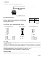
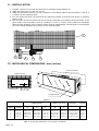
8.1.- POWER SUPPLY, RECOMMENDED WIRING
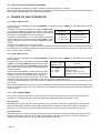
POWER SUPPLY
115 Vac (230 Vac Optional).
Main switch
FUSE and spare fuse.
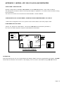
8.2.- PROTECTION FUSES
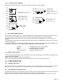
The unit has a protection fuse located on the power supply socket.
If this fuse must be replaced or changed because the power supply
is changed, use the time-lag fuse according to IEC 127/2 with the
values indicated on the table.
Power
Supply
Fuse
value
230 Vac
115 Vac
0.2 A
0.4 A
TABLE 4
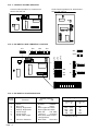
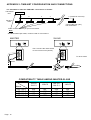
8.3.- CONTROL LINES, ALARM AND SERIAL OUTPUT
Control lines connector
Alarm connector
Serial RS422 connector
1
9
A
1
6
B
C
15
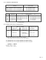
1.2.3.4.5.6.7.8.-
8
Vexc.
Vexc.
Start
GND
GND
Minutes
GND
No connection
D
9.10.11.12.13.14.15.-
Vexc.
Stop
Reset
GND
Seconds
Hours
GND
A:
B:
C:
D:
+ Alarm
No connection
No connection
- Alarm
5
1.2.3.4.5.6.7.8.9.-
9
Serial A.
Serial B.
No connection
No connection
GND
No connection
No connection
No connection
No connection.
8.4.- NOTES
The HOURS, MINUTES & SECONDS inputs are for contact closure to GND, and are pulled up to the auxiliary 15
volt rail through 4.7 KΩ.
The STOP, START and RESET inputs are normally configured to be pulled up to the auxiliary 15 volt rail through
1 KΩ, but may be internally jumpered to be pulled to GND through 1 KΩ, or pulled to GND through a high resistance
of 100 kΩ.
Debouncing for 200 mS time constant is normally incorporated on the three control inputs, but may be disabled by
removing internal jumpers.
Vexc is the Excitation Voltage for sensors supplied by the instrument (pins 1, 2 & 9).
The connections to Serial A, Serial B and GND are for the RS422 data output.
Run time uncertainty
The control inputs are sensed eight times per second, but the actual run time clock is incremented or decremented
in synchronism with the built in real time clock once per second.
This means that each start/stop condition may be inaccurate by up to one second.
Page : 8