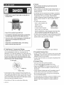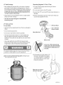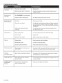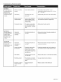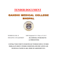
1
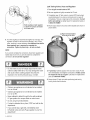
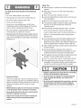
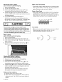
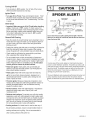
Use and Care Guide
®
LiquidPropaneGasGrill
Kenmore Model No. 415.16110800
This Grill is For
Outdoor Use Only
• Read this manual before cooking on
grill. Failure to follow all
manufacturer's
instructions could
result in fire or e×plosion which could
cause property damage, personal
injury or death.
• Combustion
by=products
produced
when using this product contain
chemicals
known to the State of
California
to cause cancer, birth
defects, or other reproductive
harm.
• Parts
• Use and Care
• Assembly
• Troubleshooting
• Safety
CAUTION
Assembly
Questions?
Call 1 =800=241 =7548
• Read and follow all Safety
Statements, Assembly
Instructions
and Use & Care Directions
before
attempting
to assemble
and cook.
• Some parts may contain sharp edges,
especially
as noted in these
instructions. Wear protective
gloves
if necessary.
Sears, Roebuck
Rules
and Co., Hoffman
Parts Ordering:
Call 1 =800=4=MY=HOME ®
To InstalledAssembler:
Leave
these instructions with
consumer.
To Consumer: Keep this
manual for future reference.
Estates,
IL 60179
U.S.A.
©2007Sears, RoebuckandCo., All Rights Reserved
Printed in China
464810408 • 80015569• 11-15-07
CALIFORNIA PROPOSITION65
1. Combustion by-products producedwhen using
this product contain chemicals known to the State of
California to cause cancer, birth defects, and other
reproductive harm.
2. This product contains chemicals, including lead
and lead compounds, known to the State of
California to cause cancer, birth defects or other
reproductive harm.
Wash your hands after handfinq this product.
if you smell gas:
1. Shut off gas to the appliance.
2. Extinguish any open flame.
3. Open lid.
4. if odor continues, keep away from the
appliance and immediately call your gas
supplier or your fire department.
1. Do not store or use gasoline or other
flammable liquids or vapors in the vicinity of
this or any other appliance.
2. An LP cylinder not connected for use shall not
be stored in the vicinity of this or any other
appliance.
Call Grill Service Center For Help And Parts
If you have questions or need assistance during assembly,
please call 1-800-241-7548. You will be speaking to a
representative of the grill manufacturer and not a Sears
employee. To order new parts call Sears at 1-800-4-MY-HOME®.
Product Record
Installation Safety Precautions
Use grill, as purchased, only with LP (propane) gas and the
regulator/valve assembly supplied. A conversion kit must be
purchased for use with natural gas.
• Grill installation must conform with local codes, or in their
absence of local codes, with either the National Fuel Gas
Code, ANSI Z223.1/NFPA 54, Natural Gas and Propane
Installation Code, CSA B149.1, or Propane Storage and
Handling Code, B149.2, or the Standard for Recreational
Vehicles,ANSI A 119.2/NFPA 1192,and CSA Z240 RV Series,
Recreational Vehicle Code, as appficable.
. All electrical accessories (such as rotisserie) must be
electrically grounded in accordance with local codes, or
National Electrical Code, ANSI / NFPA 70 or Canadian
Electrical Code, CSA C22.1. Keep any electrical cords and/or
fuel supply hoses away from any hot surfaces.
. This grill is safety certified for use in the United States and/or
Canada only. Do not modify for use in any other location.
Modification will result in a safety hazard.
Safety Symbols
The symbols and boxes shown below explain what each heading
means. Read and follow all of the messages found throughout
the manual.
iMPORTANT: Fill out the product record informationbelow.
Model Number
DANGER: Indicates an imminently hazardous situation
which, if not avoided, will result in death or serious injury.
Serial Number
See ratinglabel on grill for serialnumber.
Date Purchased
WARNING: Indicates an potentially hazardous situation
which, if not avoided, could result in death or serious injury.
r
CAUTION
For residentialuse only. Do not use for commercial
cooking.
2 • 464810408
T,o.
CAUTION: Indicates a potentiallyhazardous situation or
unsafe practicewhich, if not avoided, may result in minor
or moderate injury.
For Your Safety ......................................
2
Grill Service Center ...................................
2
Product Record Information ............................
2
One Year Full Warranty
Safety Symbols ......................................
2
Installation Safety Precautions ..........................
2
Kenmore Grill Warranty ...............................
3
If this grill fails due to a defect in material or workmanship
within one year from the date of purchase, call 1-800-4-MY
HOME®to arrange for free repair (or replacement if repair
proves impossible).
Use and Care ....................................
4-10
Parts List ..........................................
11
Parts Diagram ......................................
12
Assembly .......................................
13-24
Troubleshooting ..................................
25-27
Repair Protection
KENMORE GRILL WARRANTY
on Kenmore
Grill
Any burner that rusts through during the warranty period will
be replaced free of charge.
This warranty excludes ignitor batteries and grill part paint
loss, discoloration or rusting, which are either expendable
parts that can wear out from normal use within the warranty
period, or are conditions that can be the result of normal use,
accident or improper maintenance.
Agreements
Congratulations on making a smart purchase. Your new
Kenmore®product is designed and manufactured for years of
dependable operation. But like all products, it may require repair
from time to time. That's when having a Repair Protection
Agreement can save you money and aggravation.
This warranty is void if this grill is used for commercial or
rental purposes.
This warranty applies only if this grill is used in the United
States.
Purchase a Repair Protection Agreement now and protect
yourself from unexpected hassle and expense.
Here's what the Repair ProtectionAgreement* includes:
[]
[]
[]
[]
[]
Expert service by our 10,000 professional repair specialists
Unlimited service and no charge for parts and labor on all
covered repairs
Product replacement up to $1500 if your covered product
can't be fixed
This warranty gives you specific legal rights, and you may
have other rights which vary from state to state.
Sears, Roebuck and Co., Hoffman Estates, IL 60179
Discount of 10% from regular price of service and related
installed parts not covered by the agreement; also, 10% off
regular price of preventive maintenance check
Fast help by phone- we call it Rapid Resolution phone support from a Sears representative. Think of us
as a "talking owner's manual."
Once you purchase the Repair Protection Agreement, a simple
phone call is all that it takes for you to schedule service. You can
call anytime day or night, or schedule a service appointment
online.
The Repair ProtectionAgreement is a risk-free purchase. If you
cancel for any reason during the product warranty period, we will
provide a full refund. Or, a prorated refund anytime after the
product warranty period expires. Purchase your Repair
Protection Agreement today!
Some limitations and exclusions apply.
For prices and additional information call 1-800-827-6655.
Sears Installation Service
For Sears professional installation of home appliances, garage
door openers, water heaters, and other major home items, in the
U.S.A. call 1-800-4-MY-HOME®
464816408 • 3
LP Cylinder
• The LP cylinder used with your grill must meet the
following requirements:
• Use LP cylinders only with these required measurements: 12"
(30.5cm) (diameter) x 18" (45.7 cm) (tall) with 20 lb. (9 kg.)
capacity maximum.
• NEVER store a spare LP tank under or near grill or in
enclosed areas
, LP cylinders must be constructed and marked in accordance
with specifications for LP cylinders of the U.S. Department of
Transportation (DOT) or for Canada, CAN/CSA-B339,
cylinders, spheres and tubes for transportation of dangerous
goods. Transport Canada (TC). See LP cylinder collar for
marking.
• LP cylinder valve must have:
, Type 1 outlet compatible with
regulator or grill.
, Safety relief valve.
, UL listed Overfill Protection
OPDHand Wheel
Device (OPD). This OPD safety
• Never fill the cylinder beyond 80% full.
• An overfilled or improperly stored tank is a hazard due
to possible gas release from the safety relief valve.
feature is identified by a unique triangular hand wheel. Use
only LP cylinders equipped with this type of valve,
, LP cylinder must be arranged for vapor withdrawal and include
collar to protect LP cylinder valve. Always keep LP cylinders in
upright position during use, transit or storage.
• if you see, smell or hear escaping gas, immediately get
away from the LP tank/grill and call your fire
department.
• if the above is not followed exactly, a fire causing
death or serious injury may occur.
LP Tank Removal, Transport And Storage
, Turn OFF all control knobs and LP tank valve. Turn coupling
nut counterclockwise by hand only - do not use tools to
disconnect. Lift LP tank wire upward off of LP tank collar, then
lift LP tank up and off of support bracket, install safety cap onto
LP tank valve. Always use cap and strap supplied with valve.
Failure to use safety cap as directed may result in serious
personal injury and/or property damage.
LP cylinder in upright position for vapor withdrawal
LP (Liquefied
Petroleum Gas)
• LP gas is nontoxic, odorless and colorless when produced. For
Your Safety, LP gas has been given an odor (similar to rotten
cabbage) so that it can be smelled.
• LP gas is highly flammable and may ignite unexpectedly when
mixed with air.
LP Tank Valve
LP Cylinder
Filling
• Use only licensed and experienced dealers.
• LP dealer must purge new cylinder before filling.
Safety Cap
Retainer Strap
, A disconnected LP tank in storage or being transported must
have a safety cap installed (as shown). Do not store an LP tank
in enclosed spaces such as a carport, garage, porch, covered
patio or other building. Never leave an LP tank inside a vehicle
which may become overheated by the sun.
, Do not store an LP tank in an area where children play.
4 • 464810408
• Dealer should NEVER fill LP cylinder more than 80% of LP
cylinder volume. Volume of propane in cylinder will vary by
temperature.
• A frosty regulator indicates gas overfill, immediately close LP
cylinder valve and call local LP gas dealer for assistance.
, Do not release liquid propane (LP) gas into the atmosphere.
This is a hazardous practice.
, To remove gas from LP cylinder, contact an LP dealer or call a
local fire department for assistance. Check the telephone
directory under "Gas Companies" for nearest certified LP
dealers.
LP Tank Exchange
Connecting
o Many retailers that sell grills offer you the option of replacing
your empty LP tank through an exchange service. Use only
those reputable exchange companies that inspect, precision fill,
test and certify their cylinders. Exchange your tank only for
an OPB safety feature-equipped tank as described in the
"LP Tank" section of this manual.
1. LP tank must be properly secured onto grill. (Refer to
assembly section.)
Always keep new and exchanged LP tanks in upright position
during use, transit or storage.
Regulator To The LP Tank
2. Turn all control knobs to the OFF position.
3. Turn LP tank OFF by turning OPD hand wheel clockwise to a
full stop.
4. Remove the protective cap from LP tank valve. Always use
cap and strap supplied with valve.
, Leak test new and exchanged LP tanks BEFORE
connecting to grill,
LP Tank Leak Test
For your safety
• Leak test must be repeated each time LP tank is exchanged or
refilled.
Do not smoke during leak test.
• Do not use an open flame to check for gas leaks.
Grill must be leak tested outdoors in a well-ventilated area,
away from ignition sources such as gas fired or electrical
appliances. During leak test, keep grill away from open flames
or sparks.
, Use a clean paintbrush and a 50/50 mild soap and water
solution. Brush soapy solution onto areas indicated by arrows
in figure below. Leaks are indicated by growing bubbles.
Do not use a POL transport plug
(plastic part with external threads)!
it will defeat the safety feature of
the valve.
If "growing" bubbles appear do not use or move the LP tank.
Contact an LP gas supplier or your fire department!
A Do not use household cleaning agents. Damage to gas
train components can result.
5. Hold regulator and insert nipple into LP
tank valve. Hand-tighten the coupling
nut, holding regulator in a straight line
with LP tank valve so as not to crossthread the connection.
Nipple has to be centered
intothe LP tank valve.
464810408• 5
Leak Testing Valves, Hose and Regulator
1. Turn all grill controlknobs to OFF.
,
Be sure regulator is tightly connected to LP tank.
3. Completely open LP tank valve by turning OPD hand wheel
counterclockwise. If you hear a rushing sound, turn gas off
immediately. There is a major leak at the connection. Correct
before proceeding by calling Sears for replacement parts at
1-800-4-MY-HOME®.
Hold couplingnut and regulator
as shown for properconnection
to LP tank valve.
4. Brush soapy solution onto areas where bubbles are shown in
picture below:
A Never remove threaded
orifice at end of valve.
6. Turn the coupling nut clockwise and tighten to a full stop. The
regulator will seal on the back-check feature in the LP tank
valve, resulting in some resistance. An additional one-half to
three-quarters turn is required to complete the
connection. Tighten by hand only - do not use tools.
NOTE:
If you cannot complete the connection, disconnect regulator and
repeat steps 5 and 6. If you are still unable to complete the
connection, do not use this regulator!
• Do not insert any tool or foreign object into the valve
outlet or safety relief valve. You may damage the valve
and cause a leak. Leaking propane may result in
explosion, fire, severe personal injury, or death.
5. ff "growing" bubbles appear, there is a leak. Close LP tank
valve immediately and retighten connections. If leaks cannot
be stopped do not try to repair, Call Sears for replacement
parts at 1-800-4-MY-HOME®.
6. Always close LP tank valve after performing leak test by
turning hand wheel clockwise.
• Outdoor gas appliance is not intended to be installed
in or on a boat.
• Outdoor gas appliance is not intended to be installed
in or on an RV.
• Never attempt to attach this grill to the self-contained
LP gas system of a camper trailer or motor home.
• Do not use grill until leak-tested.
• If a leak is detected at any time, STOP and call the fire
department.
• If you cannot stop a gas leak, immediately close
LPcylinder valve and call LP gas supplier or your fire
department!
6 • 464810408
Safety Tips
,A. Before opening LP cylinder valve, check the coupling nut for
tightness.
For Safe Use Of Your Grill And To Avoid Serious
injury:
A When grill is not in use, turn offall control knobs and LP
cylinder valve.
• Do not let children operate or play near grill.
A Never move grill while in operation or still hot.
• Keep grill area clear and free from materials that burn.
• Do not block holes in bottom or back of grill.
• Check burner flames regularly.
• Use grill only in well-ventilated space. NEVER use in
enclosed space such as carport, garage, porch, covered
patio, or under an overhead structure of any kind.
,A. Use long-handled barbecue utensils and oven mitts to avoid
burns and splatters.
,A, Maximum load for sidebumer and side shelf is 10 Ibs.
,A. The grease tray must be inserted into grill and emptied after
each use. Do not remove grease tray until grill has
completely cooled.
,A. Clean grill often, preferably after each cookout. If a bristle
• Do not use charcoal or ceramic briquets in a gas grill.
(Unless briquets are supplied with your grill.)
brush is used to clean any of the grill cooking surfaces,
• Use grill at least 3 ft. from any wall or surface. Maintain
grilling. It is not recommended to clean cooking surfaces
10 ft. clearance to objects that can catch fire or sources of
ignition such as pilot lights on water heaters, live electrical
appliances, etc.
ensure no loose bristles remain on cooking surfaces prior to
while grill is hot.
,A. If you notice grease or other hot material dripping from grill
onto valve, hose or regulator, turn off gas supply at once.
Determine the cause, correct it, then clean and inspect valve,
hose and regulator before continuing. Perform a leak test.
,A. Keep ventilation openings in cylinder enclosure (grill cart) free
and clear of debris.
A Do not store objects or materials inside the grill cart
enclosure that would block the flow of combustion air to the
underside of either the control panel or the firebox bowl.
,A. The regulator may make a humming or whistling noise during
operation. This will not affect safety or use of grill.
A If you have a grill problem see the "Troubleshooting Section".
A If the regulator frosts, turn off grill and LP cylinder valve
immediately.This indicates a problem with the cylinder and it
should not be used on any product. Return to supplier!
D
__
T,o,,
m
Putting out grease fires by closing the lid is not possible.
Grills are well ventilated for safety reasons.
Apartment Dwellers:
Check with management to learn the requirements and fire
codes for using an LP gas grill in your apartment complex. If
allowed, use outside on the ground floor with a three (3) foot
clearance from walls or rails. Do not use on or under
balconies.
Do not use water on a grease fire. Personal injury may
result, if a grease fire develops, turn knobs and LP
cylinder off.
Do not leave grill unattended while preheating or burning
off food residue on Hi. if grill has not been regularly
cleaned, a grease fire can occur that may damage the
product.
• NEVER attempt to light burner with lid closed. A buildup
of non-ignited gas inside a closed grill is hazardous.
• Never operate grill with LP tank out of correct position
specified in assembly instructions,
• Always close LP tank valve and remove coupling nut
before moving LP tank from specified operation
position.
464816408• 7
Main burner Ignitor Lighting
A Do not lean over grill while lighting.
1. Open lid during lighting.
2. Turn ON valve from source or tank.
3. Push and turn Ignition Burner control knob to _- HI and
immediately press and hold Electronic Ignition button.
4. If ignition does NOT occur in 5 seconds, turn Left Burner
control knob OFF, wait 5 minutes for gas to clear and repeat
the lighting procedure.
5. To Light Other Burners turn control knob to HI.
If ignitor does not work, follow match lighting instructions.
Before Your First Cookout
. Light burners, check to make sure they are lit, close the lid and
warm up grill on HIGH for 15 minutes. This curing of paint and
parts will produce an odor only on first lighting.
Burner Flame Check
, Light burner, rotate knobs from HIGH to LOW. You should see
a smaller flame in LOW position than seen on HIGH. Always
check flame prior to each use. If only low flame is seen refer to
"Sudden drop or low flame" in the Troubleshooting Section.
After Lighting: Turn knobs to HI position for 15 minutes to preheat grill. Then turn knob to desired setting for cooking.
CAUTION
If burner does not light, turn knobs to OFF, wait 5
minutes, and try again. Always close valve during the 5
minute waiting period, if the burner does not ignite with
the valve open, gas will continue to flow out of the burner
and could accidentally ignite with risk of injury.
Hose Check
Before each use, check to see if hoses are cut, worn or kinked.
Replace damaged hoses before using grill. Use only
valve/hose/regulator specified in the Parts List.
Match-Lighting
A
1.
2.
3.
Do not lean over grill while lighting.
Open lid during lighting.
Place match intomatch holder (hanging from side of cart).
Push in and turn left knob to ,¢
HI position. Be sure burner
lights and stays lit.
4. Light right burner by pushing knob in and turning to_,. HI
position.
Sideburner
ignitor Lighting
A Do not lean over grill while lighting.
1. Open lid or cover for Side Burner during lighting.
2. Turn ON valve from source or tank.
3. Push and turn Side Burner control knob to¢ HI and
immediately press and hold Electronic Ignition button.
4. If ignition does NOT occur in 5 seconds, turn Side Burner
control knob OFF, wait 5 minutes for gas to clear, and
repeat the lighting instructions.
If ignitordoesnot work,followmatchlightinginstructions.
AfterLighting:Turnknobsto HIpositionfor warm-up.
Sideburner Match Lighting
1. Open top cover. Turn on gas at LP tank.
2. Hold lit match to any port on the burner. Push in and turn
sideburner knob to ._¢ HIGH. Be sure burner lights and
stays lit.
8 • 464810408
Normal
Hose
Kinked
Hose
Turning
Grill Off
CAUTION
. Turn all knobs to OFF position. Turn LP tank off by turning
OPD hand wheel clockwise to a full stop.
Ignitor Check
SPIDER
• Turn gas off at LP tank. Press and hold ignitor button. "Click"
should be heard and spark seen each time between collector
box or burner and electrodes. See "Troubleshooting" if no click
or spark.
l 11
ALERT!
GASCOLLECTOR
Valve Check
• important: Make sure gas is off at LP tank before checking
valves. Knobs lock in OFF position. To check valves, first
push in knobs and release, knobs should spring back. If knobs
do not spring back, replace valve assembly before using grill.
Turn knobs to LO position then turn back to OFF position.
Valves should turn smoothly.
General Grill Cleaning
, Keep the outside of your grill looking new by cleaning it once a
month with warm soap and water or a non-abrasive cleaner. If
you don't have a grill cover, wipe off dust and grime before
starting your grill.
INSIDE BURNERTUBE
VALVE
AIR
SHUTTER
VENTURI
If you notice that your grill is getting hard to light or that the
flame isn't as strong as it should be, take the time to check and
clean the burner tube.
LIFT OUT
BURNER ASSEMBLY
, Coating the cooking grids with spray-on cooking oil will keep the
food from sticking and make clean up easier. After cooking,
scrape the grates with a long handled, brass wire bristle brush.
J
, Check inside the grill bottom for grease build up and clean
often, especially after cooking fatty meat.
, Do not mistake brown or black accumulation of grease and
smoke for paint. Apply a strong solution of detergent and water
or use a grill cleaner with scrub brush on insides of grill lid and
bottom. Rinse and allow to completely air dry. Do not apply a
caustic grillloven cleaner to painted surfaces.
• Plated wire grates: Wash grates with concentrated grill
cleaner or use soap and water solution. Dry thoroughly and
store indoors between cookouts.
, Plastic parts: Wash with warm soapy water and wipe dry.
A Do not use citrisol, abrasive cleaners, degreasers or a
concentrated grill cleaner on plastic parts. Damage to and
failure of parts can result.
• Porcelain grates: Because of glass-like composition, most
residue can be wiped away with baking soda/water solution or
specially formulated cleaner. Use non-abrasive scouring
powder for stubborn stains.
REMOVE
BURNER
CLIPS
i
CLEAN OUT
VENTURI
SPIDERWEBS
INSIDEBURNERTUBE
Insome areasof thecountry,spidersor small insectshavebeen
knownto create"flashback"problems.Thespidersspinwebs,build
nestsand layeggsin thegrill'sventuritube(s)obstructingthe flow of
gas to the burner.The backed-upgas can ignitein the burnertube
behindthe controlpanel.This is knownas a flashbackand it can
damageyour grill andeven causeinjury.
Topreventflashbacksand ensuregood performancethe burnerand
venturiassemblyshouldbe removedfrom thegrill andcleaned
beforeusewheneverthe grill has beenidle for an extendedperiod.
\
J
• Painted surfaces: Wash with mild detergent or nonabrasive
cleaner and warm soapy water. Wipe dry with a soft
nonabrasive cloth.
• Stainless steel surfaces: To maintain your grill's high quality
appearance, wash with mild detergent and warm soapy water
and wipe dry with a soft cloth after each use. Baked-on grease
deposits may require the use of an abrasive plastic cleaning
pad. Use only in direction of brushed finish to avoid damage.
Do not use abrasive pad on areas with graphics.
• Cooking surfaces: If a bristle brush is used to clean any of
the grill cooking surfaces, ensure no loose bristles remain on
cooking surfaces prior to grilling. It is not recommended to
clean cooking surfaces while grill is hot.
464810408.9
Cleaning the Burner Assembly
Follow these instructions to clean and/or replace parts of burner
assembly or if you have trouble igniting grill.
1. Turn gas off at control knobs and LP cylinder,
2. Remove cooking grate and vaporiser bar.
3. Under grill remove grease cup, disconnect ignitor wire and
clips from burner. To remove clips pull down on large end of
clip attached to the valve, turn away from valve, rotate
upward and remove small end of clip from burner tube (A).
4. Inside grill remove burner assembly (B), clean ceramic
portion of electrode with rubbing alcohol and a swab.
5. Clean outside of burner with soap and water. Lay burner
upside down on flat surface, insert garden hose to force
water through tubes. Make sure water comes out of all
burner holes. Open clogged holes with a thin wire. Shake
out excess water and examine holes. Due to normal wear
6.
7.
8.
and corrosion some holes may become enlarged. If any
large cracks or holes are found replace burner.
If grill is to be stored, coat burner lightly with cooking oil.
Wrap in protective cover to keep insects out.
If not storing grill after cleaning, replace burner into grill
bottom.
To reattach clips hold large curved end away from burner
tube, insert small curved end into hole under burner tubes,
turn clip towards valve, snap into place.
VERY IMPORTANT: Burner tubes must reengage valve
openings. See illustration (A).
9. Reattach ignitor wire to electrode.
10. Reposition vaporiser bar and cooking grate. Reattach clean
grease cup to grease clip.
11. Before cooking again on grill, perform a "Leak Test'and
"Burner Flame Check".
Correct burner-to-valve engagement
Storing Your Grill
o Clean cooking grates.
o Store in dry location.
o When LP tank is connected to grill, store outdoors in wellventilated space and out of reach of children.
o Cover grill if stored outdoors.
o Store grill indoors ONLY if LP tank is turned offand
disconnected, removed from grill and stored outdoors.
, When removing grill from storage follow "Cleaning Burner
Assembly" instructions before starting grill.
Food Safety
Food safety is a very important part of enjoying the outdoor
cooking experience. To keep food safe from harmful bacteria,
follow these four basic steps:
Clean: Wash hands, utensils, and surfaces with hot soapy water
before and after handling raw meat and poultry.
Separate: Separate raw meats and poultry from ready-to-eat
foods to avoid cross contamination. Use a clean platter and
utensils when removing cooked foods.
Cook: Cook meat and poultry thoroughly to kill bacteria. Use a
thermometer to ensure proper internal food temperatures.
Chill: Refrigerate prepared foods and leftovers promptly.
For more information call: USDA Meat and Poultry Hotline at
1-800-535-4555 (In Washington, DC (202) 720-3333, 10:00 am4:00 pm EST).
How To Tell If Meat is Grilled Thoroughly
• Meat and poultry cooked on a grill often browns very fast on the
outside. Use a meat thermometer to be sure food has reached
a safe internal temperature, and cut into food to check for
visual signs of doneness.
A
• Hamburgers made of any ground meat or poultry should reach
160° F,and be brown in the middle with no pink juices. Beef,
veal and lamb steaks, roasts and chops can be cooked to 145°
R All cuts of pork should reach 160 ° R
Burner Tube
Valve
• NEVER partially grill meat or poultry and finish cooking later.
Cook food completely to destroy harmful bacteria.
B
10.464810408
• Whole poultry should reach 180° F; breasts, 170° F. Juices
should run clear and flesh should not be pink.
• When reheating takeout foods or fully cooked meats like hot
dogs, grill to 165° F, or until steaming hot.
Description.........................
Part#
Key
Description ........................
Part #
1
2
UpperLeg ..........................
80010075
44
_y
1
Grate,Side Burner ...................
80009728
2
1
Leg,LeftFront .......................
80010080
45
1
SidebumerClip......................
80015912
3
1
Leg,LeftBack .......................
80010079
46
1
WingNut...........................
80015912
4
1
Leg,RightFront ......................
80010077
47
3
#8X3/8"Self-TapScrew ...............
80015912
5
1
80010078
80010076
2
LowerHinge........................
80012696
1
LegRight Back.......................
Side Brace..........................
48
6
49
2
UpperHinge........................
80012695
7
2
SupportBracket......................
80010082
50
1
Lid Handle .........................
80012224
8
1
MatchHolder ........................
80004320
51
1
TopLid ............................
80015577
9
2
LegExtender ........................
80009820
52
4
6.5mmID, 18mmOD FiberWasher .....
80015912
10
4
HingePin ...........................
80015912
53
1
Heat Diffuser........................
80009181
11
5
HitchPin............................
80015912
54
1
CookingGrate ......................
80013209
12
12
#10-24x1-1/4"Screw ..................
80015912
55
1
SwingAway ........................
80009166
13
46
#10-24FlangeNut ....................
80015912
56
1
GreaseCup ........................
80000270
14
1
TankExclusionWire...................
80009896
57
1
Clip, GreaseCup ....................
80000271
15
1
80012240
80012241
1
Logo Plate .........................
80010544
1
UpperFrontPanel ....................
LowerFrontPanel ....................
58
16
59
1
Heat Shield,Firebox..................
80010068
17
16
#10-24x2"Screw .....................
80015912
60
2
#8-32x3/8"Screw....................
80015912
18
2
Back Brace..........................
80012236
61
4
5mm ID,9mm OD FiberWasher ........
80015912
19
2
Wheel..............................
80010191
62
1
Lid, Sideburner......................
80015899
20
1
Axle Rod............................
80010088
63
1
CondimentBasket ...................
80010102
21
1
80015912
80015583
AssemblyInstructions(English).........
80015569
1
WheelBushing.......................
ControlPanel ........................
1
22
23
1
FireBoxSupport, Left.................
80010083
1
1
AssemblyInstructions(Spanish) ........
HardwarePack......................
80015570
80015912
24
1
FireBoxSupport, Right................
80010084
25
1
26
1
Hose/Valve/Regulator
..................
El Module...........................
80015582
80014484
27
32
#10-24X1/2"Screw ...................
28
1
Heat Shield..........................
29
1
3O
1
31
32
1
WheelBushing
1
SideburnerClip
80015912
4
5
HingePin
HitchPin
80012244
1
WingScrew
TankRetainer........................
80009014
1
WingScrew .........................
FireBox ............................
80015912
80015575
1 Wing Nut
12 #10-24X1-1/4"Screw
32
#10-24X1/2"Screw
1
BurnerAssembly .....................
80012232
46
#10-24,FlangeNut
33
3
ControlKnobs .......................
80014405
2
#8-32x3/8"Screw
34
22
5mm ID, 15mmODFiberWasher........
80015912
3
#8X3/8"Self-TapScrew
35
1
Side Shelf(WithoutHole)...............
80010072
16 #10-24X2"Screw
36
1
Side Shelf(WithHole/Fascia)............
80015581
4
1/4"-20x1-1/4"Screw
37
2
MountingSide Shelf(RF/LB)............
80010073
4
1/4"-20x1/2"Screw
38
2
MountingSide Shelf(LF/RB)............
80010074
4
1/4"-20FlangeNut
39
4
1/4"-20x1-1/4"Screw ..................
80015912
22
5mm ID, 15mmOD FiberWasher
4O
4
1/4"-20x1/2"Screw....................
80015912
4
41
4
1
80015912
80006246
6.5mmID, 18mmOD FiberWasher
42
1/4"-20FlangeNut ....................
Side BurnerPan......................
4
43
1
Side BurnerAssembly.................
80015910
2
#10-24x3/4"Screws
6
5.5mmID, 19mmODFiberWasher
2
5.5mmID, 19mmOD FlatWasher
5mm ID,9mm OD FiberWasher
464810408• 11
G
®
_b
®
\
,#
(_/-o
12°464810408
LeftLeg
Placeone upperleg as shown. NOTE:Left front and left back legsdo not haveleg extenders. In front,attachupperleg, side
braceand left front leg (curve)with #10-24x1-1/4"screw and #10-24flange nut. In back,attach upperleg,sidebraceand left
back leg (straight)with #10-24x1-1/4"screw and #10-24flange nut. Do not tighten.
Attachsupportbracketin secondholefrom bottomof leg with hingepinsand hitchpins (A).
S
UpperLeg
11
HitchPin
Qty.2
_Brace
LeftFrontLeg
10
HingePin
Qty.2
13
(Curve)
Cff
12
#10-24x1-1/4"
Screw
Qty.2
LeftBackLeg
o,//
(Straight) _
12
10
13
#10-24FlangeNut
Qty.2
A
Right Leg
Placeotherupperleg as shown.Attachupperleg and rightfront leg (curve)with #10-24x1-1/4"screw and#10-24flange nut.
Thenattachupperleg and right backleg (straight)with #10-24x1-1/4"screw and #10-24flange nut Do not tighten.
Attachsupportbracketwith #10-24x1-1/4"screws and #10-24flange nuts.
13
#10-24 FlangeNut
Qty.4
13
12
#10-24xl-1/4"
Screw
Qty.4
RightFrontLeg
(Curve)
RightBack Leg\
12
(Straight) _
S_ort
Bracket
Leg Extender
464810408.13
Hooktank exclusionwire intolegswith openingfor LPcylinderon side braceside.
Tank ExclusionWire
\
Side Brace
Largeropeningside
TankExclusionWire
Lay
front legs down on the floor.
Upperand Lower Panels
D
Fit upperpanelwith two tabs betweenlegs.Attachwith #10-24x2"screws and #10-24 flange nuts.
Fit lowerpanelaroundtank exclusionwire and attachwith #10-24x2"screws and #10-24flange nuts.
17
UpperPanel
13
17
#10-24x2"Screw
Qty.8
13
#10-24Nut
Qty.8
14. 464810408
LowerPanel
Back Braces to Cart
Removepreviouslyattachedscrewsand nutsfrom upper legsasshown.Attachback braceswith #10-24x1-1/4"screws and
#10-24flange nuts.
BackBrace
/
12
#10-24xl -1/4"
Screw
Remove screws and
nuts to attach back brace
Qty. 6
12
13
#10-24FlangeNut
Qty.6
BackBrace
Wheels
Turnassemblyupsidedown.
Insertaxlerod throughwheel, legsandotherwheel.Attachwith a wheelbushingand hitch pin.
21
WheelBushing7
Qty.1
11
HitchPin
Qty.1
Axle Rod
Wheel
"Cone" side of wheel against leg
464810408.15
Control Panel and Upper FireboxSupports
Standcart upright.
In front, fit control panel betweenleft and rightlegs. Insert#10-24x2"screws to hold panelin place. Placeupperfirebox
supportsontoscrews makingsure angleside is facing thefront and attachwith #10-24flange nuts,
In back,attachupperfireboxsupportwith #10-24x2" screws and#10-24flange nuts,
17
ControlPanel
,,,_
\
UpperFirebox
Support
17
#10-24x2"Screw
Qty.8
13
#10-24FlangeNut
Qty.8
Valve/Hose/Regulatorand Electronic ignitionModule
Attachvalve/hose/regulator
assemblyto controlpanelwith #10-24x1/2"screws (A).
Removeignitorcapand plastichexnutfrom ElectronicIgnitionmoduleassembly.Insertmoduleintotheopeningon controlpanel
and attachwith the removedhexnut. PlaceAA batteryintomoduleslot with positiveend (+)facing outward.Screwignitorcap onto
module(B).
Ignitor Cap
27
27
#10-24X1/2"
Screw
Qty.2
Valve/Hose/Regulator
+
1_
!_
\
16,464810408
Electronic Ignition Module
Heat Shield
Attach heatshieldwith #10-24x1/2"screws and#10-24flange nuts.
HeatShield
27
27
#10-24Xl/2"Screw
Qty.2
13
#10-24FlangeNut
Qty.2
Tank Retainer
Inserttank retainerintoside braceand securewith wingscrew.
30
WingScrew
Qty.1
S
Retainer
464810408 • 17
Burner, Firebox and Control Knobs
Placeburnerassemblyintofirebox (A).Fastenthe burnerassemblyto thefirebox using5ramfiber washers and #10-24x 1/2"
machine screws.
Placefireboxontoupperfireboxsupportswith burnertubes belowheatshield.Makesure burner tubes are correctly engaged. If
burneris notleveledfrom left to right,adjustthe two screwsattachingvalvestemsto controlpanel.Attachignitorwireto ignitor (B).
Attachfireboxwith #10-24x1/2"screws, 5ramfiber washers and #10-24flange nuts (C).
Pushcontrol knobsonto valvestems (C).
BurnerAssembly
"-a
Firebox
27
34
13
#10-24X1/2"
Screw 5mm FiberWasher
Qty.6
Qty.6
Valve
Burner Tube
\
18. 464810408
13
#10-24FlangeNut
Qty.4
Ignitor wire
Shelves
Insertmountingbracketsintoside shelfsupportswith #10-24x1/2"screws (A).
Attachbackof leg with 1/4"-20x1-1/4"screws and!/4"-20 flange nuts, Donotfully tighten.Attachmountingbracketstofront of
leg with 1/4"-20x1/2"screws (B). Fullytightenall screws.
Repeatabovestepsto attachsideburnershelf to cart.
27
#10-24x1/2"
Screw
Qty.8
40
1/4"-20xl/2"
Screw
Qty.4
41
1/4"-20FlangeNut
Qty.4
39
1/4"-20xl-1/4"
Screw
Qty.4
A
\
MountingBracket
ShelfSuppod
SideShelf(WithoutHole)
/
4O
41
464810408.19
Sideburner
Attachsideburnervalvewith #8-32x3/8"machine screws (A).
Attachsidebumerpanwith #8x3/8"self-tap screws and 5mm ID 9mm ODfiber washers. Placesideburnerinto shelf(B).
Makesurevalve is insidesidebumertube.Attachsideburnerwith wing nut and 5mm ID 9mm ODfiber washer. Insertone end
of burnerclip intohole in sidebumertube and hookotherend aroundvalve manifold.Attachsideburnerignitorwire (C).
Presssideburnercontrolknobontovalvestem and sideburnergrateontoshelf (D).
Attachhingesto back ofshelf with #10-24xl/2"screwsand #10-24nuts (E).
Sideburner
SideburnerValve
Correctly assembled burner-to-valve engagement
D
SidebumerGrate-/J_@
ControlKnob
X
p
SideburnerIgnitorWire
E
6O
#8-32x3/8"
Screws
Qty.2
46
WingNut
Qty.1
20 • 464810408
47
#8x3/8"
Self-TapScrews
Qty.3
27
#10-24Xl/2"Screw
Qty.4
45
SidebumerClip
Qty:1
13
#10-24FlangeNut
Qty.4
LowerFireboxHinges
Attachlowerhingesto backof firebox using#10-24x1/2"screws, 5ramfiber washersand #10-24flange nuts. Thecenterflat
portionof the hingeshouldbe at the bottom(seeinset).
27
#10-24x1/2"
Screws
Qty.4
34
5mm FiberWashers
Qty.8
13
#10-24FlangeNut
Qty.4
13
27
Lid Handleand Upper Hinges
Attachhandleto lid with 5.5ramID, 19mm ODfiber washers,5.5mmID, 19ramODflat washersand #10-24x3/4"screws.
Attachupperhingesto backof lid with #10-24x1/2"screws, 5ramfiber washers and #10-24flange nuts. Hingesshouldcurve
downwardwhen properlyinstalled.
Handte_
iii
_
5.5mmFiberWashers
27
#10-24xl/2"
Screws
Qty:4
34
13
5mm FiberWashers #10-24FlangeNut
Qty:8
Qty:4
#10-24x3/4" 5.5mmID, 19mmOD 5.5mmID,19mmOD
Screws
FiberWasher
FlatWasher
Qty:2
Qty:6
Qty:2
oo
_ ;
Upper Hinge
464810408o21
Lid
Place lid assembly onto firebox, aligning hinges. Hinges on lid fit inside hinges on firebox. Secure using two hinge pins
and hitch pins (See inset ).
11
HitchPins
Qty.2
10
HingePins
Qty.2
Heat Diffuser
Place heat diffuser over screws in firebox.
Heat Diffuser
22. 464810408
Cooking Grate
Placegrateintofirebox.
CookingGrate
Swing Away
}
Insertendsof SwingAway pivotwire intoholesin sidesof grill lid.Insertendsof SwingAway legwire into holesin sidesof firebox.
NOTE:Pivotand legwires,runningside-to-side,shouldbe underwires runningfront-to-back.If pivotand leg wiresare on top,
SwingAway is installedupside-down.
Attachcondimentbasketto upperfront panelas shown.
PivotWire
SwingAway
LegWire
CondimentBasket
464810408 • 23
GreaseCup Clip and GreaseCup
Hanggreasecup clipfrom bottomof fireboxand placegreasecupintogreasecupclip.
CAUTION
FaUureto installgreasecup clip and cup
will cause hot grease to drip from bottom
of grill with risk of fire or property damage,
GreaseCup Clip
GreaseCu
LPTank
LP tank is soldseparately.Useonlywith an OPD(over-fillprotectiondevice)equippedLPtank. Filland leakcheck before
attachingto grill and regulator.See Use and Care section to correctly Leak Test and perform the Burner Flame Check.
Tankcollaropeningmustface to front of grill.Loosenwing nutfrom tank retainerbracket.Set bottomof tank into notchesin the
tank bracket.Fit tank retainerbracketontotank collarand tightenthe wingnut.
m
CAUTioN
ZL
Cylinder valve must face to front of cart once
tank is attached. Failure to install cylinder
correctly may allow gas hose to be damaged
in operation, resulting in the risk of fire.
TankRetainel
Re(
Always keep LP cylinders in
upright position during use,
transport, and storage.
LP Tank
Correctly installed
LP cylinder.
24 • 464810408
Troubleshooting
EMERGENCIES:
if a gas leak cannot be stopped,
or a fire occurs due to gas leakage, call the fire department.
Gasleakingfrom
cracked/cut/burned
hose.
, Damagedhose.
, Turnoff gas at LP tank. If hoseis cut or cracked,replace
valve/hose/regulator.
See LP TankLeakTestand Connecting
RegulatorToThe LPTank.
Gasleakingfrom LP
tank.
, Mechanicalfailuredue to rustingor
mishandling.
, Turnoff LP tankvalve.
Gasleakingfrom LP
tank valve,
, Failureof tank valvefrom mishandlingor
mechanicalfailure.
, Turnoff LP tank valve.ReturnLP tank togas supplier.
Gasleakingbetween
LP tankand regulator
connection.
, Improperinstallation,connectionnot
tight,failureof rubberseal.
, Turnoff LP tankvalve.Removeregulatorfrom cylinderand visually
inspectrubbersealfor damage.See LP TankLeakTestand
ConnectingRegulatorToTheLP Tank.
Firecomingthrough
controlpanel.
, Fire in burnertubesectionof burnerdue
to partialblockage.
, Turnoff controlknobsand LP tankvalve.Leavelid open to allow
flamesto die down.After fire is out and grill is cold, removeburner
and inspectfor spidernestsor rust.See NaturalHazardand Cleaning
The BurnerAssemblypages.
Greasefire or
continuousexcessive
flamesabovecooking
surface.
Burner(s)will not light
usingignitor.
, Toomuchgreasebuildupin burnerarea.
, Turnoff LP tank valve.Leavelid opento allowflamesto die down.
After cooling,cleanfood particlesand excessgreasefrom inside
fireboxarea,greasecup/pan/tray,and othersurfaces.
GAS ISSUES:
, Tryingto lightwrongburner.
, See instructionson controlpaneland sectionin the Use and Care.
, Burnernotengagedwith controlvalve.
, Makesure valvesare positionedinsideof burnertubes.
, Obstructionin burner.
, Ensureburnertubes are notobstructedwith spiderwebs or other
matter.See cleaningsectionof Useand Care.
, No gasflow.
, Makesure LP tank is notempty.If LP tank is notempty,referto
"Suddendrop in gasflow."
, Vaporlockat couplingnut to LP tank.
, Turnoff knobsand disconnectcouplingnutfrom LP tank.Reconnect
and retry.
, Couplingnutand LP tank valve notfully
connected.
, Turnthecouplingnut approximatelyone-halfto three-quarters
additionalturnuntil solidstop.Tightenby hand only- do notusetools.
ELECTRICALISSUES:
, Electrodecrackedor broken;"sparksat
crack."
. Replaceelectrode.
, Electrodetip not in properposition.
, Tip of electrodeshouldbe pointingtowardport holein burner.The
distanceshouldbe 1/8"to 3/16".Adjust if necessary.
, Wireand/orelectrodecoveredwith
cookingresidue.
, Cleanwireand/orelectrodewith rubbingalcoholand cleanswab.
, Wires are looseor disconnected.
, Reconnectwiresor replaceelectrode/wireassembly.
, Wires are shorting(sparking)between
ignitorand electrode.
, Replaceignitorwire.
Continuedon next
page.
464810408.25
Troubleshooting (continued}
Burner(s)will not light
usingignitor.
Burner(s)will not
matchlight.
, Push-buttonsticksat bottom..
, Replaceignitor.
, Sparkingbetweenignitorand electrode.
, Inspectwire insulationand properconnection.Replacewires if
insulationis broken.
, See "GAS ISSUES:"on previouspage.
, Impropermethodof match-lighting.
, See"Match-Lighting"sectionof Useand Care.
, Outof gas.
, Checkfor gas in LP tank.
, Excessflow valvetripped.
, Turnoff knobs,wait 30 secondsand light grill.If flamesare still low,
turnoff knobsand LPtank valve.Disconnectregulator.Reconnect
regulatorand leak-test.Turnon LP tank valve,wait 30 secondsand
thenlightgrill.
, Vaporlock at couplingnut/LPtank
connection.
, Turnoff knobsand LP tank valve.Disconnectcouplingnutfrom
tank.Reconnectand retry.
, Highor gustingwinds.
, Turnfront of grill to face windor increaseflame height.
, Lowon LP gas.
, RefillLP tank.
, Excessflow valvetripped.
, Referto "Suddendrop in gasflow"above.
, Greasebuildup.
, Cleanburnersand insideof grill/firebox.
, Excessivefat in meat.
, Trimfat from meat beforegrilling.
, Excessivecookingtemperature.
, Adjust (lower)temperatureaccordingly.
Persistentgreasefire.
, Greasetrappedbyfood builduparound
burnersystem.
, Turnknobsto OFF.Turngas off at LPtank. Leavelid in positionand
letfire burn out.After grill cools,removeand cleanall parts.
Flashback...
(firein burnertube(s)).
, Burnerand/orburnertubesare blocked.
, Turnknobsto OFF.Cleanburnerand/orburnertubes.See burner
cleaningsectionof Use andCare manual.
Unabletofill LP tank.
, Somedealershaveolder fill nozzles
with wornthreads.
, Thewornnozzlesdon'thaveenough"bite"to engagethe valve.Try
a secondLP dealer.
, Greasebuildupor foodparticlesin
end(s)of carryovertube(s).
, Cleancarry-overtube(s)with wire brush.
Suddendrop in gas
flow or lowflame.
Flamesblowout.
Flare-up.
Oneburnerdoesnot
lightfrom other
burner(s).
26. 464810408
Troubleshooting - Electronic ignition
SECTIONI
Nosparksappearat
anyelectrodeswhen
ignitionbuttonis
pushed;no noisecan
be heardfrom spark
module.
SECTIONII
Nosparksappearat
anyelectrodeswhen
ignitionswitchis
pushed;noisecan be
heardfrom spark
module.
SECTIONIII
Sparksare present
butnot at all
electrodesand/ornot
atfull strength
, Batterynotinstalled
properly.
, Checkbatteryorientation.
. Installbattery(makesurethat "+"and "-"
connectorsare orientedcorrectly,with "+" end up
and "-" end down.)
. Deadbattery.
. Has batterybeenused
previously?
, Replacebatterywith newAA-sizealkalinebattery.
. Buttonassemblynot
installedproperly.
. Checkto insurethreadsare
properlyengaged.Button
shouldtravelup and down
withoutbinding.
. Unscrewbuttoncapassemblyand reinstall,making
sure threadsare alignedand engagedfully.
. Faultysparkmodule.
. If no sparksare generated
with new batteryand good
wireconnections,moduleis
faulty.
. Replacesparkmoduleassembly.
. Outputlead
connectionsnot
connected.
, Are output connectionson
and tight?
, Removeand reconnectall outputconnectionsat
moduleandelectrodes.
, Outputlead
connectionsnot
connected.
Are output connectionson
and tight?
, Removeand reconnectall outputconnectionsat
moduleandelectrodes.
. Arcingto grill away
from burner(s).
If possible,observegrill in
dark location.Operate
ignitionsystemand lookfor
arcingbetweenoutputwires
and grill frame.
. If sparksare observedotherthanfrom burner(s),
wire insulationmaybe damaged.Replacewires.
, Weak battery.
All sparkspresentbutweak
or at slow rate.
. Replacebatterywith a newAA-sizealkalinebattery.
. Electrodesare wet.
Has moistureaccumulated
on electrodeand/orin burner
ports?
, Use paper towelto removemoisture.
. Electrodescrackedor
broken"sparksat
crack".
. Inspectelectrodesfor
cracks.
. Replacecrackedor brokenelectrodes.
464810408 • 27
Your Home
iiiiiiiiiiiiiiiiiiiiiiiiiiiiiiiiiiii
Forrepair-in yourhome-ofall
majorbrand appliances,
iiiiiiiiiiiiiiiiiiiiiiiiiiiiiiiiiiii
lawn and garden equipment, or heating and cooling systems,
iiiiiiiiiiiiiiiiiiiiiiiiiiiiiiiiiiiinomatterwhomadeit, nomatterwhosoldit!
iiiiiiiiiiiiiiiiiiiiiiiiiiiiiiiiiiii Forthe replacement parts, accessories and
iiiiiiiiiiiiiiiiiiiiiiiiiiiiiiiiiiiiowner'smanualsthatyouneedtodo-it-yourself,
iiiiiiiiiiiiiiiiiiiiiiiiiiiiiiiiiiii
gorSears professional installationofhomeappliances
iiiiiiiiiiiiiiiiiiiiiiiiiiiiiiiiiiii
anditemslikegaragedooropenersandwaterheaters,
':;i_i_i_i_i_i
iiiiiiiiiiiiii
iiiiiiiiiiiiii
iiiiiiiiiiiiii
iiiiiiiiiiiiii
iiiiiiiiiiiiii
iiiiiiiiiiiiii
iiiiiiiiiiiiii
HHHHHHH
HHHHHHH
iiiiiiiiiiiiiiiiiiiiiiiiiiiiiiiiiiii
1-800-4-MY-HOME
iiiiiiiiiiiiii
® (1-800-469-4663)
iiiiiiiiiiiiii
iiiiiiiiiiiiii
iiiiiiiiiiiiiiiiiiiiiiiiiiiiiiiiiiiiiiiiiiiiiiiiiiiiiiiiiiiiiiiiiiiiiiii
Callanytime,
andCanada)www.sears.com
dayornight(U.S.A,
www.sears.ca
'"'";'i'i'i'i'"'
iiiiiiiiiiiiiiiiiiiiiiiiiiiiiiiiiiii
Forexperthomesolutionsadvice:www.managemyhome.com
Our Home
For repair of carry-in items like vacuums, lawn equipment,
and electronics, call or go on-line for the location of your nearest
Po,t Ropoi,
so,vicooto,
o
1-800-488-1222
(U.S.A)
1-800-469-4663
(Canada)
HHHHHHHHi_
Call anytime, day or night
www.,ea,,.co,,,
To purchase a protection agreement on a product serviced by Sears:
1-800-827-6655 (U.S.A.)
1-800-361-6665 (Canada)
Para pedir servicio de reparaci6n
a domicilio, y para ordenar piezas:
Au Canada pour service en francais:
1-800-LE-FOYER Mc
iiiiiiii!!:!!:!!:!!:!!:!!:!!:!!:!!:!!:!!:!!:!!:!!i
1-888-SU-HOGAR
iiiiiiiiiiiiiiiiiiiiiiiiiiiiiiiiiiiii
_
® Registered
®
(1-800-533-6937)
(1-888-784-6427)
Trademark
/ TMTrademark
/ sMService
www.sears.ca
Mark of Sears
Brands,
® Mama Registrada / _ Marca de Fabrica / s_ Marca de Servicio de Sears
_° Marque de commerce / _DMarque depos6e de Sears Brands, LLC
LLC
Brands,
LLC
® Sears
Brands,
LLC