1
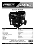
Owners
Manual
FOR POTABLE WATER
HEATING ONLY
NOT SUITABLEFOR
SPACEHEATING
Model No.
153.320392HT
153.320393 HT
153.320492 HT
153.320493 HT
153.320592 HT
153.320593 HT
153.320692 HT
153.320693 HT
153.320892 HT
153.320893 HT
30 Gal.
30 Gal.
40 Gal.
40 Gal.
50 Gal.
50 Gal.
66 Gal.
66 Gal.
80 Gal.
80 Gal.
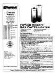
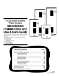
POWER
MISER
LECTRIC
WATER
HEATER
• Safety Instructions
• Installation
• Operation
Caution:
TM
12
• Care and Maintenance
• Troubleshooting
• Parts List
Read and Follow
All Safety Rules and
Operating Instructions
Before First Use of
This Product.
GAMA certificationappliesto all residential electric water heaters with
capacities of 20 to 120Gallons. Input rating of 12 Kw or less at a voltage
no greater than 250
_i, WARNING
READ THE GENERAL SAFETY SECTION BEGINNING ON INSIDE COVER
AND THEN THIS ENTIRE MANUAL BEFORE INSTALLING OR OPERATING THIS WATER HEATER.
Save this Manual for Future Reference.
Sears, Roebuck
and Co., Hoffman
Estates,
IL 60179
U.S.A.
Safety Precautions
_, WARNING
AWARNING
HAZARD OF ELECTRICAL SHOCKI Before removing any
access panels or servicing the water heater, make sure the
electrical supply to the water heater is turned "OFF". Fmluro
to do this could result in DEATH, SERIOUS BODILY INJU"
OR PROPERTY DAMAGE.
I
I
Improper installation, adjustment, alteration, service or mainte- I
nance can causeDEATH, SERIOUS BODILY INJUI_, OR PROPERTY DAMAGE. Refer to this manual for assistanceor consult
AWARNING
your ocal Sears Service Center for further nformation.
HOTTER WATER CAN SCALD: Water heatersare intended
to producehot water. Water heated to a temperature which
will satisfyspaceheating,clotheswashing,dishwashing,and
other sanitizingneeds can scaldand permanentlyinjureyou
uponcontact.Some peopleare more likelyto be permanently injuredby hot water than others.These includethe elderly,
children, the infirm, or physically/mentallyhandicapped.If
anyoneusing hot water in your home fits into one of these
groupsor if there is a localcode or state law requiring a certain temperature water at the hot water tap, then you must
take specialprecautions.In additionto usingthe lowestpossible temperature settingthat satisfiesyour hot water needs,a
means suchas a mixing valve, shallbe usedat the hot water
taps used by these people or at the water heater. Mixing
valvesare availableat plumbingsupplyor hardware stores.
Follow manufacturers instructions for installation of the
valves.Before changingthe factory setting on the thermostat, read the "Temperature Regulation" section in this
manual.
A WARNING
At the time of manufacturethiswater heaterwasprovidedwith
a combinationtemperature-pressures
relief valvecer_dfled
by a
nationally recognizedtestinglaboratorythat maintains periodic
inspectionof productionof listed equipmentor materials, as
meetingthe requirementsfor ReliefValvesand AutomaticGas
ShutoffDevicesfor Hot Water SupplySystems,and the latest
editionof ANSI Z2h22 and the cederequirements of ASME. If
replaced, the valvemust meet the requirementsof localcodes
but not lessthan a combinationtemperatureand pressurerelief
valvecertifiedasmeetingthe requirements for ReliefValvesand
AutomaticGas ShutoffDevicesfor Hot Water SupplySystems,
ANSI Z21.22 by a nationally recognizedtestinglaboratorythat
maintains periodic inspectionof productionof listedequipment
or materials.
The valvemust be marked with a maximum setpressurenot to
exceedthe marked hydrostaticworkingpressureof the water
heater(150 Ibsdsq.
in.)and a dischargecapacitynot lessthan the
water heater input rate as shownon the model rating plate.
(Electricheaters, watts dividedby 1000x 3415equal BTU/Hr.
rate.)
Yourlocaljurisdictionalauthority,while mandating the useof a
temperature-pressure
relief valvecomplyingwith ANSI Z2h22
andASME,mayrequire a valvemodel differentfrom the onefurnishedwith the waterheater.
Compliancewith suchlocalrequirements mustbe satisfiedby
the installeror end userof the water heaterwith a locallyprescribedtemperature-pressure
relief valveinstalledin the designated openingin the water heater in placeof the factory furnishedvalve.
For safeoperationof the water heater,the reliefvalvemustno_
be removedfrom it'sdesignated
openingor plugged.
The temperature-pressure
relief valvemust be installeddirectly
intothe fittingofthewater heaterdesignated
for the relief valve.
Position the valvedownwardand providetubing sothat anydischargewill exit onlywithin 6 inchesabove,or at any distance
belowthe structuralfloor.Be certainthat no contact is made
with anylive electricalpart. The dischargeopeningmustnot be
blockedor reduced in size under any circumstances.
Excessive
length,over 30 feet, or useof more than four elbowscancause
restriction and reducethe discharge
capacityufthe valve.
No valveor otherobstructionisto be placedbetweenthe relief
valveand the tank. Do not connecttubingdirectlyto discharge
drainunlessa 6"air gapisprovided.Topreventbodilyinjury,haz.
ard to life,or propertydamage,the relief valvemustbe allowed
to discharge
water in quantitiesshouldcircumstances
demand.If I
the dischargepipeis not connectedto a drainor other suitabh
means,the water flowmaycausepropertydamage.
The DischargePipe:
Mustnot be smallerin sizethan the outletpipesizeof the
valve,or haveanyreducingcouplings
or otherrestrictions.
Mustnot be pluggedor blocked.
Mustbe of materiallistedfor hotwater distribution.
Must be installed so as to allow complete drainage
both the temperature-pressure relief valve, and the
discharge
pipe.
Mustterminateat an adequatedrain.
Mustnot haveanyvalvebetweenthe reliefvalveandtank.
AWARNING
WATER HEATERS EQUIPPED FOR ONE VOLTAGE ONLY:
This water heater is equipped for one type voltage only.
Check the rating plate near the bottom access panel for the
correct voltage. DO NOT use this water heater with any voltage other than the one shown on the model rating platt
Failure to use the correct voltage can cause problems which
can result in DEATH, SERIOUS BODILY INJURY, OR PROPERTY DAMAGE. If you have any questions or doubts consult
your electric company.
_,WARNING
INSULATING JACKETS: When installing an external water
heater insulation jacket on an electric water heater:
a. DO NOT cover the temperature-pressure relief valve.
b. DO NOT put insulation over the access covers or any
accessareas.
c. DO NOT cover or remove operating instructions, and safety related warning labels and materials affixed to the water
heater.
_,WARNING
Do not use this applianceif any part of it hasbeen under
water. An electrical short or malfunction could occur.The
water heater shouldbe replaced.
• , CAUTION
WATER HEATERS EVENTUALLY LEAK: Installation of the
water heater must be accomplished in such a manner that if
the tank or any connections should leak, the flow of water
will not cause damage to the structure. For this reason, it is
not advisable to install the water heater in an attic or upper
floor. When such locations cannot be avoided, a suitable
drain pan should be installed under the water heater. Drain
pans are available at your oca Sears Store. Such a drain pan
must be piped to an adequate drain. Under no circumstances I
is the manufacturer or Sears to be held liable for any water
damage in connection with this water heater.
2
Table of Contents
_€,,,-.oal,._y
Precautions .........................................................................................................
2
Table of Contents ..........................................................................................................
3
Introduction ..........................................................................................................................
4
Product bpecihcations ........................................................................................................
4
Preparing for the New Installation ............................................................................
4
Materials and Basic Tools Needed .............................................................................
5
Materials Needed ......................................................................................................................................................................
Basic Tools ................................................................................................................................................................................
5
5
Installation Instructions ...............................................................................................
6-15
Removing the Old Water Heater ...............................................................................................................................................
6
Facts to Consider About the Location .......................................................................................................................................
7
Facts to Consider About the Convertible Lower Element
.............................................................................................
7
Water Piping .............................................................................................................................................................................
8
Temperature-Pressure Relief Valve.............................................................................................................................................
9
Filling the Water Heater ............
..............................
10
Converting the Lower Element ..........................................................................................................................................
10-12
Wiring Diagrams ....................................................................................................................................................................
13
Wiring ....................................................................................................................................................................................
14
Installation Checklist ..............................................................................................................................................................
15
Service and Adjustment
1
I
A
.....................................................................................................
16-20
Temperature Regulation ..........................................................................................................................................................
Thermostats ............................................................................................................................................................................
Thermostat Settings ......................
. ...........................................................
Upper Thermostat Adjustment ...............................................................................................................................................
Lower Thermostat Adjustment ...............................................................................................................................................
Temperature-Pressure Relief Valve Operation ..........................................................................................................................
Draining..................
................
......).
.............
Element Cleaning and Replacement ..................................................................................................................................
Drain Valve Washer Replacement ...........................................................................................................................................
Service ....................................................................................................................................................................................
"_ " "
"lroubleshooting
16
16
16
16
17
17
17
+*..)._
18-20
20
20
Guide ................................................................................................
21-24
Start Up Conditions ..........
.
Thermal Expansion ...............................................................................................................................................................
Strange Sounds .....................................................................................................................................................................
Operational Conditions .....................................................................................................................................................
Smelly Water .........................................................................................................................................................................
Air n Hot Water Faucet's.....................................................................................................................................
Rumbling Noise ....................................................................................................................................................................
High Temperature Shut Off System .................................................................................................................................
Not Enough or No Hot Water ..............................................................................................................................................
Water is Too Hot ..................................................................................................................................................................
Leakage Checkpoints ..............................................................................................................................................................
21
21
21
22-23
22
22
22
22-23
23
23
24
Parts Order List .....................................................................................................................
28-31
Warranty .........................................................................................................................
32
3
Introduction
Thank
You
Abbreviations
for purchasing
a Sears water heater.
Properly installed and maintained,
it should give you years of
trouble free service. If you should decide that you want the new
water beater professionally
installed, contact the local Sears
Service Center or any Sears store. They will arrange for prompt,
quality installation by Sears authorized contractors.
Product
MODEL
NUMBER
TANK
CAPACITY DIMENSIONS IN INCHES
IN GALLONS DIAMETEI
HEIGHT
RECOVERY RATE
GALS. PER HOUR
@ 90°E RISE
20
46_
17.3
25.0
153.320492HT
153.320493HT
40
20
60_
17.3
25.0
58_
17.3
25.0
61
17.3
25.0
62
17.3
25.0
153.320892HT
153.320893HT
Instruction
Manual
Specifications
30
153.320692HT
153.320693HT
In This
U.L.-Underwriters
Laboratories,
333
Pfingsten
R
Northbrook,
IL 60062
National Electrical Code-This publication is available from your
local government
or public library or electric company or by
writing to U.L. above.
ANSI-American
National Standards Institute
153.320392HT
153.320393HT
153.320592HT
153.320593HT
Found
50
66
80
22
24
26¼
ELEMENT
WATTAGE
MINIMUM
AT 240 VOLTS
WIRE SIZE*
UPPER
LOWER
(GAUGE)
3800
3800
3800
3800
3800
3800
3800
3800
3800
3800
3800
5500
3800
5500
3800
5500
3800
5500
3800
5500
12
10
12
I0
12
10
12
10
12
10
MAXIMUM FUSE
OR CIRCUIT
BREAKER
SIZE (AMPS)
20
30
20
30
20
30
20
30
20
30
*Wiring size based on standard 60°C copper wire. If distance from fuse box to water heater is more than 90 feet, refer to your local electrical code.
Preparing
•
for the New Installation
Read the "Safety Precautions" section, page 2 of this manual
first and then the entire manual carefully. If you don't follow
the safety rules, the water heater will not operate properly. It
could
cause DEATH,
SERIOUS
BODILY
INJURY
AND/OR PROPERTY DAMAGE.
This manual contains instructions for the installation, operation, and maintenance of this electric water heater. It also
contains warnings throughout the manual that you must read
and be aware or. All warnings and all instructions are essential to the proper operation of the water heater and your safety. Since we cannot put everything on the first few pages,
READ THIS ENTIRE MANUAL
BEFORE ATTEMPT1NG TO INSTALL
OR OPERATE
THE
WATER
HEATER.
•
The installation must conform with the instructions in this
manual; electric company rules; and Local Codes, or in the
absence of Local Codes,
with the latest edition
of the
National Electrical Code. This publication
is available from
your local government or public library or electric company
or by writing Underwriters
Laboratories,
333 Pfingsten
Road, Northbrook,
IL 60062.
If afrer reading this manual you have any questions or do not
understand any portion of the instructions, call Sears Service
Center.
Carefully plan the place where you are going to put the water
heater. Correct electrical wiring and connections
are very
important
in preventing death from possible electrical shock
and fires.
Examine the location to ensure the water heater complies with
the "Facts to Consider About the Location" section.
For California installation this water heater must be braced,
anchored, or strapped to avoid falling or moving during an
earthquake. See instructions for correct installation procedures. Instructions may be obtained from your local dealer,
wholesaler, public utilities or California office of the State
Architect, 400 P Street, Sacramento, CA 95814
Materials
and Basic Tools Needed
Materials Needed
To simplify the installation
Sears has available the installation
parts shown below. You may or may not need all of these materials, depending on your type of installation.
WATER HEATER HEAT TRAPS
HELP REDUCE HEAT LOSS DUE
TO THERMAL SYPHONING
WATER HEATER INSTALLATION KIT WITH FLEXIBLE
CONNECTORS
FOR 314" OR
t/2" THREADED
OR COPPER
LUMBING
EXPANSION
TANKS FOR THERMAL
EXPANSION
CONDITIONS
AVAILABLE
IN 2 GALLON AND 5 GALLON CAPACITY
THROUGH
LOCAL SEARS SERVICE
CENTERS
Basic Tools
You may or may not need
type of installation.
These
Sears
DRAIN PANS AVAILABLE IN 20"
DIAMETER FOR WATER HEATERS
HAVING A DIAMETER 18" OR LESS,
24" DIAMETER FOR WATER HEATERS
HAVING A DIAMETER 22" OR LESS
AND AVAILABLE IN 28" DIAMETER
FOR WATER HEATERS HAVING A
DIAMETER 26" OR LESS
all of these tools, depending
on your
tools can be purchzsed
at your local
Stole.
Pipe Wrench (2)
Screwdriver
6 Foot Tape or Folding Rule
Garden Hose
Drill
Pipe Dope or Teflon Tape
ADDITIONAL
TOOLS NEEDED
WHEN
SWEAT SOLDERING
Tubing Cutters or Hacksaw
Propane Torch
Soft Solder
Solder Flux
Emery Cloth
Wire Brushes
6 FOOT TAPE
GARDEN
HOSE
SLOT-HEAD
SCREW
DRIVER
WRENCH
PHILLIPS
SCREWDRIVER
PROPANE TORCH
ROLL OF LEAD FREE
SOFT SOLDER
(SQUEEZE
PIPE DOPE
TUBE)
ROLL OF TEFLON TAPE
(Use only on water connections)
DRILL
ROLL OF EMERY
CLOTH
SOLDER
FLUX
TUBING
CUTTER
Installation
Instructions
Removing the Old Water
Heater
OTurn
Q
Q
"OFF" electrical supply to the water heater.
a. If you have copper piping to the
heater, the two copper water pipes can be
cut with a hacksaw approximately 4" away
from where they connect
to the water
heater. This will avoid cutting off the pipes
too short. Additional
cuts can be made
later if necessary. Disconnect the temperature-pressure relief valve drain line. When
the water heater is drained, disconnect the
hose from the drain valve. Close the drain
valve. The water heater is now completely
disconnected and ready to be removed.
Turn "OFF" the water supply to the
water heater at the water shutoffvalve or
water meter.
Qb.
QAttach
valve
drain
drain
faucet
water
a hose to the water heater drain
and put the other end in a floor
or outdoors. Open the water heater
valve. Open a nearby hot water
which will relieve pressure in the
heater and speed draining.
I
AWARNING
If you have galvanized pipe to the water
heater, loosen the two galvanized
pipe5
with a pipe wrench at the union in eadn
line. Also disconnect the piping remaining
to the water heater. These pieces should be
saved since they may be needed when
reconnecting
the new water
heater.
Disconnect
the temperature-pressure
relief
valve drain line. When the water heater is
drained,
disconnect
the hose from the
drain valve. Close the drain valve. The
water heater is now completely disconnected and ready to be removed.
[
The water passingout of the drain valve may be extreme- J
ly hot. To avoid being scalded, make sure all connectionsI
are tight and that the water flow is directed away from
any person.
Q
Cbeck again ,to make sure the electrical supply is
turned OFF to the water heater. Then disconnect
the electrical supply connection
from the water
heater junction box.
• , CAUTION
I
Mineral buildup or sediment may have accumulated in the
old water heater. This causes the water heater to be J
much heavier th.an normal and this residue, if spilled out,
could cause staining.
I
Installation
Instructions
(cont'd)
Facts to Consider About the
Location
Facts to Consider About The
Convertible Lower Element
You should carefully choose an indoor location for the new
water heater, because the placement is a very important consideration for the safety of the occupants in the building and for
the most economical use of the appliance. This water heater is
not intended for outdoor installation.
The Upper Element (if a double element model), is a conventional 3800 watt element which only operates at its rated
wattage on 240 volts. (See rating plate on water heater).
Whether
replacing an old water heater or putting the water
heater in a new location, the following critical points must be
observed.
• The location selected should be indoors as close to and as
centralized with the water piping system as possible. This
water heater, as well as all water heaters, will eventually leak.
Do not install without adequate drainage provisions where
water flow will cause damage.
-_ CAUTION
WATER HEATERS EVENTUALLY LEAK: Installation of
the water heater must be accomplishedin sucha manner
that if the tank or any connectionsshouldleak, the flow of
water will not cause damage to the structure. For this
reason, it is not advisableto install the water heater in an
attic or upper floor. When such locationscannot be avoided, a suitable drain pan should be installed under the
water heater. Drain pans are available at your local Sears
stores. Such a drain pan must be piped to an adequate
drain. Under no circumstances is the manufacturer or
Sears to be held liable for any water damage in connection with this water heater.
The Lower Element of the water heater can be converted from
operation at 3800 watts to 5500 watts on a 240 volt system.
Read and follow water heater warnings and instructions. If after
reading these instructions in this manual, if you do not understand any portion, call Sears Service Center.
iI WARNING
Before making the conversion to 5500 watts, check the
(I) power supply...must be 240 volts, (2) wiring...10 gauge
AWG, Type TW, 60°C or equivalent, and (3) Circuit
breakers or fusing...capable of 30 amp loading. Also, the
installation must conform with this manual, local codes
and electric utility rules. Failure to comply can result in
DEATH. SERIOUS BODILY INJURY. OR PROPERTY
DAMAGE.
150
CAUTION
INSTALLATION
IN RESIDENTIAL GARAGES. The
water heater must be located and/or protected so it is
not subjectto physicaldamage by a mov ng veh cle.
• The location selection must provide adequate clearances for
servicing and proper operation of the water heater.
NOTE: Whether or not the element conversion is made the
model rating plate must be marked. Using a hard point ink
pen, check the appropriate block within the model rating
plate, which is located adjacent to the lower access panel.
Installation
Water
Instructions
(cont'd)
Piping
AWARNING
HOTTER WATER CAN SCALD: Water heaters are
intended to produce hot water. Water heated to a temperature which will satisfyspace heating, clothes washing,
dish washing, and other sanitizing needs can scald and
permanently injure you upon contact. Some people are
more likely to be permanently injured by hot water than
others. These include the elderly, children, the infirm, or
)hysically/mentally handicapped. If anyone using hot
water in your home fits into one of these groups or
there is a local code or state law requiring a certain temperature water at the hot water tap, then you must take
special precautions. In addition to using the lowest possible temperature setting that satisfies your hot water
needs, a means such as a mixing valve, shall be used at
the hot water taps used by these people or at the water
heater. Mixing valves are available at plumbing supply or
hardware stores. Follow manufacturers instructions for
installation of the valves. Before changingthe factory setting on the thermostat,
read the "Temperature
Regulation" section in this manual.
Installation
completed
using Sears
Installation Kit
FLEXIBLE
WATER
CONNECTORS
HOT OUTLET
TO HOUSE
THREADED TO
SWEAT COUPLING
SHUT-OFF
VALVE
COLD INLET
WATER LINE
THREADED
TO
SWEAT COUPLING
O
The illustration shows the attachment of the water pipin,_ to the
water heater. The water heater is equipped
with ¾ water
connections.
If a water heater is installed in a closed water supply system;
such as one having a back-flow preventer, check valve, water
meter with a check valve, etc. in the cold water supply; means
shall be provided to control thermal expansion. Contact the
local utility or local Sears Service Center on how to control this
situation.
TEMPERATUREPRESSURE
RELIEF VALVE
--
DISCHARGE
PIF
(Do not cap or pk
NOTE: If using copper robing, solder tubing to an adapter
before attaching the adapter to the cold water inlet connection. Do not solder the cold water supply line directly to the
cold water inlet. It will harm the dip tube and damage the
tank.
• Look at the top cover of the water heater. The water outlet is
marked hot. Put two or three turns of teflon tape around the
threaded end of the threaded-to-sweat
coupling and around
both ends of the _" threaded nipple. Using flexible connectors, connect the hot water pipe to the hot water outlet of the
water heater.
• Look at the top cover of the water heater. The cold water inlet
is marked cold. Put two or three turns of teflon tape around
the threaded end of the threaded-to-sweat
coupling and
around both ends of the ¾ threaded nipple. Using flexible
connectors, connect the cold water pipe to the cold water
inlet of the water heater.
NOTE: Your water heater is super insulated to minimize
heat loss from the tank. Further reduction in heat loss can be
accomplished by insulating the hot water lines from the
water heater.
6" AIR GAP
FLOOR
DRAIN
Installation
Instructions
Temperature-Pressure
Relief Valve
(cont'd)
&WARNING
The temperature-pressure relief valve must be manually
operated at least once a year. Caution should be taken to
ensure that (I) no one is in front of or around the outlet
of the temperature-pressure relief valve discharge line,
and (2) the water manually dischargedwill not cause any
bodily injury or property damage becausethe water may
be extremely hot.
If after manually operating the valve, it fails to completely
reset and continues to release water, immediately, close
the cold water inlet to the water heater, follow the draining instructions, and replace the temperature-pressure
relief valve with a new one.
A WARNING
At the time ofmanufacture thiswater heaterwas providedwith
a combinationtemperature-pressures
relief valvecertifiedby a
nationallyrecognizedtestinglaboratorythat maintainsperiodic
inspectionof productionof listedequipment or materials,as
meetingthe requirementsfor ReliefValvesand AutomaticGas
ShutoffDevicesfor Hot Water SupplySystems,and the latest
edition of ANSI Z21.22 and the code requirements of ASHE. If
replaced,the valvemustmeet the requirementsof localcodes
but not lessthan a combinationtemperature andpressurerelief
valvecertifiedasmeetingthe requirementsfor ReliefValvesand
AutomaticGasShutoffDevicesfor Hot Water SupplySystems,
ANSI Z21.22 by a nationally recognizedtestinglaboratorythat
maintainsperiodicinspectionof productionof listedequipment
or materials.
The valvemust be markedwith a maximum set pressurenot
to exceed the marked hydrostaticworking pressure of the
water heater (150 Ibsdsq.in.) and a dischargecapacity not
lessthan the water heater input rate as shownon the model
rating plate.(Electric heaters - watts dividedby 1000x 3415
equalBTU/Hr. rate,)
Yourlocaljurisdictional
authority,while mandatingthe useof a
temperature-pressurerelief valvecomplyingwith ANSI Z21.22
and ASME,may require a vane model differentfrom the onefurnishedwith the water heater.
Compliancewith suchlocalrequirements must be satisfiedby
the installeror end user of the water heater with a locallyprescribed temperature-pressurerelief valveinstalledin the designatedopeningin the water heater in placeof the factoryfurnishedvalve.
Forsafeoperationofthe water heater,the reliefvalvemustnot
beremovedfrom it'sdesignated
openingor plugged.
The temperature-pressure
relief valvemustbe installeddirectly
intothe fittingofthe water heaterdesignated
for the relief valve.
Positionthe valvedownwardand providetubing sothat anydischargewill exit onlywithin 6 inchesabove,or at any distance
belowthe structuralfloor.Be certainthat no contactis made
with anyliveelectricalpart. The dischargeopeningmustnot be
blockedor reduced in sizeunder anycircumstances. Excessive
length,over30 feet, or useof more than four elbowscan cause
restriction and reducethedischarge
capacityofthe valve.
No valveor other obstructionisto be placedbetween the relief
valveand the tank. Do not connecttubingdirectlyto discharge
drain unlessa 6" air gap is provided.To preventbodilyinjury,
hazard to life, or property damage,the relief valve must be
allowedto dischargewater in quantitiesshouldcircumstances
demand. If the dischargepipe is not connectedto a drain or
i other suitable means, the water flow may cause property
damage.
: The DischargePipe:
: Must not be smallerin sizethan the outlet pipesizeofthe
valve,or haveanyreducing couplingsor other restrictions.
Must not be pluggedor blocked.
• Must be of material listedfor hot water distribution.
!
Must be installedsoasto allow completedrainageof both
the temperature-pressurerelief valve, and the discharge
pipe.
t
Mustterminate at an adequatedrain.
Mustnot haveanyvalvebetween the rolief valveand tank.
HOT
.TEMPERATUREPRESSURE
RELIEF VALVE
(Do not cap or plug)
6" AIR GAP
FLOOR DRAIN
T&P RELIEF
VALVE PROBE
TEMPERATUREPRESSURE
RELIEF VALVE
INTO TANK
NIPPLE
' ''
T&P
SHANK
LENGTH
• If a shor_shank (le_s than 2") temperature-pressureielie$valve is to be installed
(as shown),a nippleand couplingmust _ used
• _f a longshank (2" or longer)is to be inst_led, de not use thenipple and co_ng
InStallTemperalu_e
Pressurep_otectNeeou_nent _quired by _c_.aleodes,b_ notlessthana comb+ha.
bo,, Temperature
Pressure
Relief
Valve certified as meeting the requi;ements
for Relief
Valves and
AutomaticGas Shutoff_
1o'Hot-water Supd.ySystems¸A_S 721 22by _ na_0nally
_ecc_zed test.
mg lab_aton/that _
periodc_specaca ofpn:ducbt_ol Im_:l equprnemor marshalsTheva;ve
rn_ beode_l_, pmV,
ded _€_hM:ing, c<_
mstal_d soI_ d_so3an_e
canexatonlyw_n 6 _ch_s
above,ot at anydistancebelowB-,as_tural IIo_, andcannotcontactanylive electricalpa_
Forsaleope_on c+If_ wate_heater,the gekefValvem_str,_ bet_',o_d or p_gge¢
See rnar_Jalheading- Temperatule-pressureRel+elValve for installal_on
a_ maintenanceof Relief
Valve¸clschargepipeandc6_etsafetypre_ubor,s
9
Installation
Filling the Water
Instructions
(cont'd)
Heater
To fill the water hearer with water:
• Close the water heater drain valve by turning the handle to
the right (clockwise). The drain valve is on the lower front of
the water hearer.
Open the cold water supply valve to the water heater.
NOTE: The cold water supply valve must be left open
when the water heater is in use.
To insure complete filling of the tank, allow air to exit by
opening the nearest hot water faucet. Allow water to run
until a constant flow is obtained. This will let air out of the
water heater and the piping.
A CAUTION
Never usethis water heater unlessit is completely full of
water. To prevent damage to the tank and heating element, the tank must be filled with water. Water must
flow from the hot water faucet before turning "ON"
power.
NOTE: Whether or not the element conversion is made the
model rating plate must be marked. Using a haxdpoint ink
pen, check the appropriate block within the model rating
plate, which is located adjacent to the lower access panel.
Check all new water piping for leaks. Repair as needed.
Converting
Element
Necessary element conversion parts are located in a small bag
contained within the electrical junction box on top of the water
heater.
the Lower
CONVERSION
These instructions only cover the conversion of the convertible
element, read this entire manual before attempting to install or
operate the water heater. The water heater is factory set to operate at 3800 watts. The lower element can be converted to operate at 5500 watts. Refer to the "Facts to Consider About the
Convertible Lower Element" section.
The Upper Element, (if a double element model) is a conventional 3800 watt element which only operates at its rated
wattage on 240 volts, (See rating plate on water heater).
BUSS
The Lower Element of the water heater can be converted from
operation at 3800 watts to 5500 watts on a 240 volt system.
I.
PARTS
BAR
Before beginning the conversion
supply to the water heater.
turn "OFF"
electric power
If after reading these instructions and this manual, if you do not
understand any portion, call Sears Service Center.
AWARNING
Before making the conversion to 5500 watts, check the
(I) power supply...mustbe 240 volts, (2) wiring...10 gauge
AWG, Type TW, 60°C or equivalent, and (3) Circuit
breakers or fusing...capableof 30 amp loading. Also, the
installation must conform with this Manual, local codes
and electric utility rules. FAILURE TO COMPLY CAN
RESULT IN DEATH, SERIOUS BODILY INJURY OR
PROPERTY DAMAGE.
AWARNING
HAZARD
OF ELECTRICAL
SHOCK! Before removing
any access panels or servicing the water heaterp make
sure the electrical supply to the water heater is turned
"OFF".
FAILURE TO DO THIS COULD
RESULT IN
DEATH,
SERIOUS BODILY INJURY, OR PROPERTY
I DAMAGE.
10
Installation
Instructions
2. The convertible
element is located behind the lower access
panel of the water heater. Remove the two screws securing
the access panel, and remove panel.
(cont'd)
5. Lower Element: LiE out the tab as shown to unclip the terminal cover from the thermostat. The terminal cover can now
be removed from the thermostat.
Lift out tab to until!
ternllnaJ
cover
from
,AC
t_ermosta_
TERMINAL
COVER
CLIPPED TO THER-
P"O%?
TATTH's
PLASTIC TABS ON
'BOTH SIDES OF
TERMINAL
COVER
HOLD IT IN
PLACE.
THERMOSTAT
BRACKET
3. Remove the adjustment dial from the thermostat
pulling it directly away from the thermostat.
by gently
q(--- TANK
_LEMENT
6. Remove the screws from terminal
the looped end of the wire aside.
4. Remove the insulation
2 of the element,
and move
block to expose the opening.
7. The buss bar is labeled 5500 W. Place the buss bar over
terminals 2 and 3 with the 5500 W visible. Install the extra
screw provided into terminal 3.
8. The wire removed from terminal 2 has a looped end. It must
remain looped and now be placed (as shown) on top of the
buss bar, over the opening of terminal 2, and secured using
the remaining screw.
11
Installation
Instructions
(cont'd)
Converting the Lower
Element (cont'd)
9. Tighten
terminals
2 and
3 to ensure
proper
electrical
12. The adjustment dial has a "D" shaped opening that matches
a "D" shaped shaft on the thermostat. Align the opening in
the dial to the shaft and gently push the dial onto the shaft.
connection.
AWARNING_
Failure to lighten terminal screws can cause a fire which
can result in DEATH, SERIOUS BODILY INJURY, OR I
PROPERTY DAMAGE.
1
10. Replace terminal cover on the thermostat,
notch is in place over the tab.
making sure the
13. Replace the access panel.
AWARNING
Make sure the thermostat is flush against the tank, the
terminal cover is in place, and the insulation is replaced.
Failure to do so can result in DEATH, SERIOUS BODILY
NJURY, OR PROPERTY DAMAGE.
l 1. Replace the insulation block so that it completely
thermostat and element.
14. Complete wiring to the water heater, or if completed, turn
"ON" electric power to the water heater after filling the
tank with water.
covers the
A CAUTION
Never use this water heater unless it is completely full ofl
water. To prevent damage to the tank and heating element, the tank must be filled with water. Water must J
flow from the hot water faucet before turning "ON"
power.
I
12
Installation
Wiring
Instructions
Diagrams
(cont'd)
TO ELECTRIC
POWER SUPPLY
STANDARD
WIRING
FOR
2 WIRE
LEAD WATER
HEATERS
NON.SIMULTANEOUS
OPERATION
240 VOLT DOUBLE
ELEMENT
LJNCTION
BLACK
RED
UPPER
E.C,O.
THERMOSTAT
BUSS BAR
_O
\
_
&
°
a
UPPER-"
ELEMENT
FOR 5500 WATTS
EOR3800W="
WIRING
FOR 3 WIRE LEAD WATER
NON-SIMULTANEOUS
OPERATION
240 VOLT DOUBLE ELEMENT
ENT
HEATERS
THREE
TIME CLOCK
OPERATES BOTTOM
TO ELECTRIC
_
POWER SUPPLY
BUSS BAR
L2
L[
SWITCH
ELEMENT
_
L2 L2
JWL_BI
"OFF PEAK" METER
OPERATES BOTTOM ELEMENT
ELEMENT
*_--r_L2LIL2
Li
_
FOR 5500 WATTS
BOX
ONLY
-'P
TO "OFF
PEAK'METER
BOX
LOWER
T'STAT
FOR TWO
TO ELECTRIC
POWER SUPPLY
WIRE
LI
OW_J
YELL
FOR 3800 WATTS
*NOTE: Some Lower Hi-Temp Limit
Switches may have 4 terminals. Use
only the 2 terminals on left.
ONLY
IUNCTION
LACK
YELLO
YOU
TO TIME
CLOCK SWITCH
A NCTION
CK
YELLO
TO ELECTRIC
POWERSUPPLY
OF FIELD
HAVE
ONNECTIONS
t
UPPER E.C.O. &
THERMOSTAT
TYPES
LOWER
HEATING ELEMENT
13
CONNECTION
L2
UNCTION
_CK
BOX
MAY
Installation
Instructions
(cont'd)
Wiring
A CAUTION
C. Flexible metal conduit or flexible metallic tubing shall be
permitted for grounding if all the following conditions are
met:
I
Never use this water heater unless it is completely full of
water. To prevent damage to the tank and heating element, the tank must be filled with water. Water must
flow from the hot water faucet before turning on power.
1. The length in any ground return path does not exceed
6 feet.
2. The circuit conductors contained therein are protected
by overcurrent devices rated at 20 amperes or less.
You must provide all wiring of the proper size outside of the
water heater. You must obey local codes and electric company
requirements when you install this wiring.
3. The conduit
or tubing
approved for grounding.
If you are not familiar with electric codes and practices, or if you
have any doubt, even the slightest doubt, in your ability to connect the wiring to this water heater, obtain the service of a competent electrician. Contact your Sears salesperson to arrange for
a professional electrician.
in fittings
For complete grounding
details and all allowable exceptions,
refer to the latest edition of the National Electrical Code.
4. A standard _" conduit opening has been made in the water
heater junction box for the conduit connection.
5.
AWARNING
WATER HEATERS EQUIPPED FOR ONE VOLTAGE
ONLY: This water heater is equipped for one type voltage
only. Check the rating plate near the bottom accesspanel
for the correct voltage. DO NOT use this water heater
with any voltage other than the one shownon the model
rating plate. Failure to use the correct voltage can cause
problems which can result in DEATH SERIOUS BODILY
NJURY, OR PROPERTY DAMAGE. If you have any questions or doubts consult your electric company.
Wiring Diagrams (See Wiring Diagrams Section) have been
supplied showing the two most common types of connections between the water heater and the power supply. You can
easily see which type connection you have by removing the
junction box cover on top of the water heater.
A. Two Wire Connection
Diagrams:
is the most common
requiring you to simply connect red to red, black to black,
and the ground wire to the green ground screw in the junction box of the water heater.
B. Three Wire Connection
Diagram: is used when you aa
connecting
the water heater to power a supply that has a
"T'me Clock" or Off Peak Meter. To make these connections refer to block 1 or 2 in this wiring diagram for the type
of system you have.
A CAUTION
If wiring from your fuse box or circuit breaker box was
aluminum for your old water heater, replace it with copper wire. If you wish to reuse the existing aluminum wire,
have the connection at the water heater made by a competent electrician.
Contact your Sears salesperson to
arrange for a professional electrician.
NOTE:
water
Peak"
lower
lock
1. Provide a way to easily shut off the electric power when working on the water heater. This could be with a circuit breaker
or fuse block in the entrance box or a separate disconnect
switch.
6.
If you have purchased a three wire connection
heater but you are not on a "Time Clock" or "Off
meter and have a standard two wire connection
supply, simply follow the connection
diagram in
3. of the Three Wire Connection
Diagram.
Use wire nuts and connect the power supply wiring
wires ins'de the water heaters junction.
to the
7. The water heater must be electrically
"grounded"
by the
installer. A green ground screw has been provided on the
water heater's junction
box. Connect ground wire to this
location.
2. Install and connect a circuit directly from the main fuse or
circuit breaker box. This circuit must be the right size and
have its own fuse or circuit breaker. Refer to the chart in the
"Product Specifications"
section for the correct size wire and
fuse or circuit breaker.
3. If metal conduit
is terminated
8. Replace the wiring junction
cover using the screw provided.
is used for the grounding conductor:
A. The grounding
electrode conductor
shall be of copper,
aluminum,
or copperclad aluminum. The material shall
be of one continuous length without a splice or joint.
CONDUIT
B. Rigid metal conduit, intermediate
metal conduit, or electrical metallic
tubing may be used for the grounding
means if conduit
or tubing is terminated
in fittings
approved for grounding.
'GREEN
SCREW
14
Installation
Instructions
(cont'd)
Installation Checklist
Whether or not the element conversion is made, the model
rating plate must be marked. Using a hard point ink pen,
check the appropriate
block within the model rating plate,
which is located adjacent to the lower access panel.
HOT
COLD
Is the fuse or circuit breaker size correct as shown in the chart
in the "Product Specifications" section?
Are the wires from the circuit breaker or fuse service to the
water heater's junction box on the correct wire size (gauge) as
shown in the chart m the Product Speclficauons
section.
Is the new temperature-pressure
installed, and piped to an adequate
Pressure Relief Valve" section.
relief valve properly
drain? See "TemperatureTEMPERATUREPRESSURE
ls the water heater completely filled with water? See "Filling
the Water
Heater"
instructions
in the "Installation
Instructions" section.
Will a water leak damage anything?
About the Location sectmn.
RELIEF VALVE
See "Facts to Consider
Are the cold and hot water lines connected to the water heater
correctly? See "Water Piping" instructions in the "Installation
Instructions" section.
Is there adequate clearance for maintenance around the water
heater?
Do you need to call your electric
wiring?
company
to check
_DISCHARGE
PIPE
(Do not cap or plug)
your
De
I6
AIR GAP
FLOOR DRAIN
MODEL RATING
15
PLATE
Service
and Adjustment
Temperature
Regulation
A WARNING
The lower thermostat is factory set at its lowest position which
approximates
120°F (Hot) and is adjustable if a different water
temperature is desired. Read all warnings in this manual and on
the water heater before proceeding.
HOTTER WATER CAN SCALD: Water heaters are
intended to produce hot water. Water heated to a temperature which will satisfyspace heating, clothes washing,
dish washing, and other sanitizing needs can scald and
permanently injure you upon contact. Some people are
more likely to be permanently injured by hot water than
others. These include the elderly, children, the infirm, or
physically/mentally handicapped. If anyone using hot
water in your home fits into one of these groups or if
there is a local code or state law requiring a certain temperature water at the hot water tap, then you must take
specialprecautions. In addition to using the lowest possible temperature setting that satisfies your hot water
needs, a means such as a mixing valve, shall be used at
the hot water taps used by these people or at the water
heater. Mixing valves are available at plumbing supply or
hardware stores. Follow manufacturers instructions for
installation of the valves. Before changingthe factory setting on the thermostat,
read the "Temperature
Regulation" sectionin this manual.
AWARNING
Temperature
HOT-Is
setting of approximately
130°E
B-Is a thermostat
setting of approximately
140°E
C-Is a thermostat
setting of approximately
150°E
a thermostat setting of approximately 160°E It
is recommended
that the dial be set lower whenever possible.
NOTE: Water temperature range of 120°--140°F
mended by most dishwasher manufacturers.
]
in a bathtub or shower.
a thermostat
setting of approximately
120°F,
which will supply hot water at the most economica] temperatures.
A-Is a thermostat
VERY HOT-Is
Never allow small children to use a hot water tap, or to|
draw their own bath water. Never leave a child or handi-|
capped person unattended
Settings
recom-
Upper Thermostat
Adjustment
]
Thermostats
NOTE: It is not necessary to adjust the upper thermostat.
However, if it is adjusted above the factory set point of
120°F (HOT) it is recommended that it not be set higher
than the lower thermostat setting.
The thermostat(s)
of this water heater have been factory set at
their lowest position which approximates
120°F (Hot) to reduce
the risk of scald injury.
The upper thermostat is adjustable if a different water temperature is desired.
Read all warnings
in the "TemperatureRegulation" section before proceeding.
The upper thermostat is factory set at its lowest position which
approximates 120°F (Hot) and is adjustable if a different water
temperature is desired. Read all warnings in this manual and on
the water heater before proceeding.
1. Turn "OFF" the electrical
junction box.
power
to the water heater
at the
2. Take "OFF" the access panel.
3. The slotted adjustment (using a screwdriver) can be turned
clockwise (___.J)
to increase the temperature
setting or
counter clockwise (k.._.._)
to decrease the temperature settmg.
4.
4
Replace the access panel.
5. Turn "ON"
OI
UPPER THERMOSTAT
ADJUSTABLE
BEHIND
UPPER ACCESS PANEL
16
the power supply.
Service
and Adjustment
(cont'd)
Lower Thermostat
Adjustment
Failure to install and maintain a new properly listed temperature-pressure relief valve will release the manufacturer
from any
claim which might result from excessive temperature or pressure.
The lower thermostat
is adjustable if a different water temperature is desired.
Read all warnings
in the "TemperatureRegulation' section before proceed'ng.
The adjustment
dial can be turned clockwise
increase
the temperature
setting
or counter
(_
) decrease the temperature setting.
(_...J)
clockwise
to
to
A WARNING
If the temperature-pressure
relief valve on the appliance
weeps or discharges periodically, this may be due to thermal expansion. Your water heater may have a check valve
installed in the water line or a water meter with a check
valve. Consult your local Sears Service Center for further
information. Do not plug the temperature-pressure
relief
valve.
Draining
The water heater should be drained if being shut down during
freezing temperatures.
Also periodic draining and cleaning of
sediment from the tank may be necessary.
• Before beginning
water heater.
AWARNING
LOWER THERMOSTAT ADJUSTABLE
THROUGH
LOWER ACCESS PANEL
Temperature-Pressure
Valve Operation
The temperature-pressure
at least once a year.
• CLOSE
the cold water inlet valve to the water heater.
operated
• OPEN a nearby hot water faucet and leave open to allow for
draining.
TEMPERATURE-PRESSURE
• Connect
adequate
RELIEF VALVE
• OPEN
DISCHARGE
I
HAZARD
OF ELECTRICAL
SHOCK! Before removing I
any access panels or servicing the water heater, make
sure the electrical supply to the water heater is turned I
"OFF".
Failure to do this could result in DEATH, SERIOUS BODILY INJURY, OR PROPERTY DAMAGE.
Relief
relief valve must be manually
turn "OFF" the electric power supply to the
a hose to the drain
drain or outdoors.
valve
and terminate
to an
the water heater drain valve to allow for tank draining.
NOTE: If the water heater is going to be shut down and
drained for an extended period, the drain valve should be
left open with hose connected allowing water to terminate
to an adequate drain.
PIPE
• Close the drain valve.
AWARNING
• Follow "Filling
the Water Heater"
Installat on Instrucnons
secnon.
The temperature-pressure
relief valve must be manually
operated at least once a year. Caution should be taken to
ensure that (I) no one is in front of or around the outlet of
the temperature-pressure relief valve discharge line, and (2)
the water manually discharged will not cause any property
damage or bodily injury. The water may be extremely hot.
If after manually operating the valve, it fails to completely
reset and continues to release water, immediately close the
cold water inlet to the water heater, follow the draining
instructions, and replace the temperature-pressure
relief
valve with a new one.
instructions
in the
• Turn "ON" power to the water heater.
A CAUTION
I
N_.ver use this water heater unless it is completely full I
water. To prevent damage to the tank and heating element, the tank must be filled with water. Water must I
flow from the hot water faucet before turning "ON"
power.
17
Service
and Adjustment
(cont'd)
Element Cleaning/
Replacement
NOTE: These instructions are written for element cleaning
and element replacement for the lower element. If it is necessary to dean or replace the upper element, then repeat these
instructions.
To remove
replace it:
the element
1. Before beginning
water heater.
from your
turn "OFF"
tank
in order
3. Attach a hose to the water heater drain valve and put the
other end in a floor drain or outdoors. Open the water heater
drain valve. Open a nearby hot water faucet which will relieve
pressure in the water heater and speed draining.
to clean or
the electric power supply to the
AWARNING
]
The water passingout of the drain valve may be extremely ]
hot. To avoidbeingscalded,makesureall connections
are tight
andthat the water flowisdirectedawayfrom anyperson.
4. Remove the two screws securing the access panel, and remove
panel.
AWARNING
HAZARD
OF ELECTRICAL
SHOCK! Before removing I
any access panels or servicing the water heater, make I
sure the electrical supply to the water heater is turned]
"OFF".
Failure to do this could result in DEATH, SERI- I
OUS BODILY INJURY, OR PROPERTY DAMAGE.
|
2. Turn off the water supply to the water heater
shutoffvalve or water meter.
5. After you have removed the lower access panel, remove the
adjustment
dial from the thermostat
by gently pulling it
directly away from the thermostat.
at the water
6. Remove the insulation
18
block to expose the opening.
Service
and Adjustment
(cont'd)
12. Close the water heater drain valve by turning the handle to
the right (clockwise). The drain valve is on the lower front
of the water heater.
7. Lift out the tab as shown to unclip the terminal cover from
the thermostat.
The terminal cover can now be removed
from the thermostat.
13. Open the cold water supply valve to the water heater.
NOTE: The cold water supply valve must be left open
when the water heater is in use.
Lif_ out tab to uncli F
terminal
¢Gver from
I_ ernl°stat"
TERMINAL
COVER
CLIPPED TO THER-
+ATT"'s
14. To insure complete filling of the tank, allow air to exit by
opening the nearest hot water faucet. Allow water to run
until a constant flow is obtained. This will let air out of the
water heater and the piping.
PLASTIC
TABS ON
'BOTH SIDES OF
TERMINAL
COVER
HOLD IT IN
PLACE,
THERMOSTAT
BRACKET
A CAUTION
Never use this water heater unlessit is completely full of I
water. To prevent damage to the tank and heating ele- I
ment, the tank must be filled with water. Water must I
flow from the hot water faucet before turning "ON"
power.
,ill-- TAN K
-ELEMENT
LOWER
THERMOSTAT
15.
Check element for water leaks. If leakage occurs, tighten
element or repeat steps 2 and 3, remove element and reposition gasket. Then repeat steps 11 through 15.
16. Reconnect the two wires to the element and then check to
make sure the thermostat remains firmly against the surface
of the tank.
8. Disconnect the two wires on the element and unscrew the
old element from the tank.
9.
Clean the area around the element opening.
Remove any
sediment from or around the element opening and inside
the tank.
10. lfyou are cleaning the element you have removed, do so by
scraping or soaking in vinegar or a de-liming solution.
17.
Replacement elements must (I) be the same voltage and
(2) no greater wattage
than listed on the model rating 1
AWARNING
p ate affixed to the water heater.
11. A new gasket should be used in all cases to prevent a possible water leak. (See Element Gasket in the Parts Order
List" Chart). Place the new element gasket on the thread
side of the cleaned or new element and screw into tank,
securing tightly using an element wrench.
19
Replace the terminal
cover on thermostat.
Service
and Adjustment
Drain Valve Washer
Replacement
Element Cleaning/
Replacement
(cont'd)
18. Replace the insulation block so that it completely
thermostat and element.
(cont'd)
NOTE: For replacement, use a '%/' x _" x %" thick washer
available at your nearest hardware store. For ordering a
replacement washer, refer to the "Parts Order List" section.
covers the
• Before beginning turn "OFF" the electrical power supply to
the water beater.
AWARNING
HAZARD OF ELECTRICAL SHOCK! Before removing
any access panels or servicing the water heater, make
sure the electrical supply to the water heater is turned I
"OFF". Failure to do this could result in DEATH, SERIOUS BOD LY INJURY,OR PROPERTY DAMAGE.
• Follow "Draining"
instructions
in the "Service and
Adjustment" section.
• Turning counter clockwise, remove the hex cap below the
screw handle.
• Remove the washer and put the new one in place.
• Screw the handle and cap assembly back into the drain valve
and retighten using a wrench. DO NOT OVER TIGHTEN.
• Follow "Filling the Water Heater" instructions
in the
"Installation Instructions" section.
• Check for leaks.
19. The adjustment dial has a "D" shaped opening that matches
a D shaped shaft on the thermostat. Align the opening in
the dial to the shaft and gently push the dial onto the shaft.
j
• Turn "ON" electric power to the water heater.
_
)._
_
20. Turn "ON" electric power to water heater.
HANDLE
AND
CAP ASSEMBLY
WASHER
Service
Before calling for repair service, read the Start Up Conditions
and Operational
Conditions
found in the Troubleshooting
Guide of this manual.
If a condition persists or you are uncertain about the operation
of the water heater, let a qualified person check it out.
Contact SEARS Repair Services at 1-800-4-MY-HOME
(1-800-469-4663).
A CAUTION
[
Never use this water heater unlessit is completely full of]
water. To prevent damage to the tank and heating ele- I
ment, the tank must be filled with water. Water must I
flow from the hot water faucet before turning "ON"
power.
2O
Troubleshooting
Guide
Start Up Conditions
THERMAL
EXPANSION
HOT
COLA2
Water supply systems may, because of such events as high line
pressure, frequent cut-offs, the effects of water hammer among
others, have installed devices such as pressure reducing valves,
check valves, back flowpreventers,
etc._to control these types of
problems. When these devices are not equipped with an internal
by-pass, and no other measures are taken, the devices cause the
water system to be closed. As water is heated, it expands (thermal expansion) and closed systems do not allow for the expansion of heated water.
WATERHEATER
• COLDWATER
INLET FITTING
EXPANSION
TANK
(I)
PRESSURE GAUGE
WATER HEATER
COLD WATER
INLET FITrlNG
HOT
Tank
Model
Number
Tank Capacity
In Gallons
Dimensions
in Inches
Diameter
Length
Pipe Fitting
On Tank
153•331020
2
8 inches
12_ inches
_" Male
153.331050
5
11 inches
14_ inches
_" Male
FLOOR,
CE|UNG
jols'_,ETC.
COLD
STRAPPING
Specifications
(3)
i
Expansion
WATER
SHUTOFF
RECOMMENDED INSTALLATION
(VERTICAL MOUNTING)
It is recommended that any devices installed which could create a
closed system have a by-pass and/or the system have an expansion tank to relieve the pressure built by thermal expansion•
Thermal expansion tanks are available from Sears stores and
through the Sears Service Centers. Contact the local plumbing
inspector, water supplier and/or the Sears Service Center for
assistance in controlling these situations.
Expansion
1
(2)
The water within the water heater tank expands as it is heated and
increases the pressure of the water system• If the relieving point of
the water heater's temperature-pressure
relief valve is reached, the
valve will relieve the excess pressure. The temperature-pressure
relief valve is not intended for the constant relief of thermal
expansion. This is an unacceptable condition and must be corrected.
Thermal
(3)
PRESSURE
REDUCING
VALVEWITH
BY-PASS
11)
EXPANSION
PRESSURE
REDUCING INLETCOLD
VALVEWITH
WATER
BY-PASS
SHUTOFF
{zl
Tank Sizing Chart
PRESSURE GAUGE
Inlet*
Expansion
Capacity
Tank
Needed
Water Heater Capacity
]Water
[Pressure
_si
30
_
[ 50psi
2
2
166psi
70psi
_2-
80psi
--2"
*Highest recorded inlet water
regulated water pressure.
_
40
2
__
[2
[
5
pressure
[
:
50
2
,
I
5
5
/5
(Gallons)
66_
ALTERNATE RECOMMENDED
INSTALLATION
82
(HORIZONTAL
MOUNTING)
_
5
5_
5
[_
i
fi
5
STRANGE
5
]
5
Possible noises due to expansion and contraction of some metal
parts during periods of heat-up and cool-down do not represent
narmful or dangerous conditions•
in a 24 hour period
or
NOTE= Expansion
tanks are pre-charged
with a 40 psi air
charge. If me i,nlet water pressure is higher than 40 psi, the
expansion tanks air pressure must be adjusted to match that
pressure, but must not be higher than 80 psi.
21
SOUNDS
Troubleshooting
Operational
SMELLY
Guide (cont'd)
Conditions
WATER
RUMBLING
In each water heater there is installed at least one anode rod (see
parts section) for corrosion protection of the tank. Certain water
conditions will cause a reaction between this rod and the water.
The most common complaint associated with the anode rod is
one of a "rotten egg smell". This odor is derived from hydrogen
sulfide gas dissolved in the water. The smell is the result of four
factors which must all be present for the odor to develop:
a. a concentration
of sulfate in the supply water.
b. little or no dissolved oxygen in the water.
c. a sulfate reducing bacteria within the water heater. (This
harmless bacteria is non-toxic to humans.)
d. an excess of active hydrogen in the tank. This is caused by
the corrosion protective action of the anode.
In some water areas, scale or mineral deposits will build up on
your heating elements. This buildup will cause a rumbling noise.
Follow "Element Clean'ng/Replacement'
instructions
to clean
and replace the elements.
HIGH
IN HOT
WATER
SHUT
Follow the resetting instructions
behind the access panel.
OFF
SYSTEM
which
refer to the high limit
NOTE: If your water heater is connected to an "OFF PEAK"
clock, and uses the "3 wire lead" wiring diagram in the
"Wiring Diagram" section, then the waterheater will have a
hi-limit on both the upper and lower thermostats. Follow
the instructions to reset the hi-limit behind the upper and
lower access pands.
If the smelly water persists after the anode replacement and chlorination treatment, we can only suggest that continuous chlorination and filtering conditioning
equipment be considered to
eliminate the water problem.
"AIR"
TEMPERATURE
The water heater has a high limit shut off system with a reset
button located on the thermostat.
Smelly water may be eliminated or reduced in some water heater
models by replacing the anode(s) with one of less active material,
and then chlorinating
the water heater tank and all hot water
lines. Contact the local Sears Service Center for further information concerning an Anode Replacement Kit #9001453
and this
Chlorination Treatment.
Do not remove the anode leaving the tank unprotected.
doing so, all warranty on the water heater tank is voided.
NOISE
•
Before beginning,
water
turn
"OFF" electrical power supply to the
heater.
By
FAUCET'S
AWARNING
HYDROGEN GAS: Hydrogen gas can be produced in a
hot water system that has not been used for a long period of time (generally two weeks or more). Hydrogen gas
is extremely flammable and explosive. To prevent the
possibility of injury under these conditions, we recommend the hot water faucet be opened for several minutes at the kitchen sink before any electrical appliances
which are connected to the hot water system are used
(such as a dishwasher or washing machine). If hydrogen
gas is present, there will probably be an unusual sound
similar to air escapingthrough the pipe as the hot water
faucet is opened. There must be no smoking or open
flame near the faucet at the time it is open.
AWARNING
HAZARD OF ELECTRICAL SHOCK! Before removing
any access panels or servicing the water heater, make
sure the electrical supply to the water heater is turned
"OFF". Failure to do this could result in DEATH, SERIOUS BODILY INJURY,OR PROPERTY DAMAGE.
22
Troubleshooting
HIGH
TEMPERATURE
(cont'd)
SHUT
OFF
Guide (cont'd)
SYSTEM
NOT
Remove the insulation
•
Reset the high limit by pushing
"RESET".
block to expose the opening.
in the red button
OR NO
HOT
WATER
In a new installation, the water heater may not be properly
connected. Make sure the cold water supply valve is open.
Review and check piping installation. Make sure that the
cold water line is connected to the cold water inlet to the
water heater and the hot water line to the hot water outlet
on the water heater.
• Remove the two screws securing the access panel and remove
panel.
•
ENOUGH
marked
Make sure the electrical supply to your water heater is
"ON".
Check for loose or blown fuses in your water heater circuit.
Circuit breakers weaken with age and may not handle their
rated load and should be replaced.
Make certain the disconnect switch, if used, is in the "ON"
position.
--RESET
Check to see the electric service to your house has not been
interrupted. If this is the case, contact the electric company.
BUTTON
Are the thermostats
set to the desired
"Temperature Regulation" section.
temperature?
See
If you had experienced very hot water and now no hot
water, the problem may be due to the high temperature
shut off system. See "High Temperature Shut Off System'
in the "Troubleshooting" section.
• Replace the insulation block so that it completely covers the
thermostat and element.
• Replace the access panel.
During very cold weather, the incoming water will also be
colder and it will require a longer time to become heated.
• Turn "ON" electric power to the water heater.
The hot water usage may exceed the opacity of the water
heater. If so, wait for water heater to recover aher abnormal
demand. Also examine pipes and faucet's for possible water
leaks.
If the high limit must be reset again, call Sears Service
I Department to find out why the high limit turned "OFF"
/i, CAUTION
I
! the electric power.
If you can not determine
Service Department.
WATER
IS TOO
Adjust the thermostat
Regulation" section.
23
the problem,
then call the Sears
HOT
to a lower setting. See the "Temperature
Troubleshooting
Guide (cont'd)
Leakage Checkpoints
Use this gu!de to check a "Leaking" water heater. Many suspected "Leakers are not leaking tanks. Often the source of the water
can be found and corrected.
A CAUTION
If you are not thoroughly familiar with electric codes, the water
heater, and safety practices, contact your local _Sears Service
Center to check the water heater.
®
®
©
*Condensation may be seen on pipes in humid
or pipe connections may be leaking.
®
the tank s comp ete y fu of water.
A CAUTION
weather
Never use this water heater unless it is completely full of
water. To prevent damage to the tank and heating element, the tank must be filled with water. The water must
flow from the hot water faucet before turning "ON"
J
power.
J
The primary anode rod may be leaking.
Small amounts of water from temperature-pressure
relief valve may be due to thermal expansion or high
water pressure in your area.
temperature-pressure
@ *The
the tank fitting.
relief valve may be leaking at
The elements may be leaking at the tank fitting.
AWARNING
HAZARD
OF ELECTRICAL
SHOCK1 Before
removing any access panels or servicing the water
heater, make sure the electrical supply to the
water heater is turned "OFF".
Failure to do this
could result in DEATH,
SERIOUS
BODILY
INJURY, OR PROPERTY DAMAGE.
Turn electrical power "OFF", remove access panels and
fold back insulation. If leaking around elements, follow
proper draining
instructions
and remove element.
Reposition or replace gasket on element. Place element
into opening and tighten securely. Then follow "Filling
the Water Heater" instructions in the "Installation
Instructions" section.
®
©
®
Water from drain valve may be due to the valve being
opened slightly.
*The drain valve may be leaking at the tank fitting.
*Water in the water heater bottom or on the floor may
be from condensation,
loose connections
or the
temperature-pressure
relief valve. DO NOT replace
the water heater until a full inspection of all possible
water sources is made and necessary corrective steps
taken.
Leakage from other appliances,
seepage should also be checked.
I
Read this manual first, then before checking the water
heater make sure the electric supply has been turned
"OFF", and never turn the electric supply "ON" before
water lines, or ground
NOTE: *To check where threaded portion enters
tank, insert cotton swab between jacket opening and
fitting. If cotton is wet, follow "Draining" instructions in the "Service and Adjustment" section and
then remove fitting. Put pipe dope or teflon tape on
the threads and replace. Then follow "Filling the
Water Heater" instructions in the "Installation
Instructions" section.
24
Notes
25
Notes
26
Notes
27
Parts Order
List
KENMORE POWER MISER TM 12 ELECTRIC WATER HEATERS
MODEL NUMBERS:
153.320392
153.320393
153.320492
153.320493
153.320592
HT
HT
HT
HT
HT
30
30
40
40
50
Gal.
Gal.
Gal.
Gal.
Gal.
NOTE: A
2
UPPER ELEMENT: These water heaters are equipped with
3800 watt elements.
LOWER ELEMENT: These water heaters are equipped with
factory installed convertible elements, which can he operated
at 3800 watts or 5500 watts. Convertible elements are not
offered as replacement parts.
3
ELEMENT ORDERING INFORMATION
If a replacement 3800 watt, 240 volt dement is needed, order
item no. 42-31906 replacement element. If at the time of installation, the water heater was converted to operate at 5500 watts,
order item number 42-31908 replacement dement. (See model
rating plate "If Converted" box).
NOTE:
i
B
These water heaters are equipped
with a Roto-Swirl
tube to retard a build-up of dissolved solids.
TM
24
dip
2O
19
18
11
28
4
Parts Order
KENMORE POWER
MODEL NUMBERS:
153.320392
153.320393
153.320492
153.320493
153.320592
KEY
NO.
1.
2.
3.
4.
5.
6.
7.
8.
9.
10.
11.
12,
13.
14.
15.
16.
17.
18.
19.
20.
21.
22.
23.
24.
#
HT
HT
HT
HT
HT
30
30
40
40
50
M1SER
TM
List (cont'd)
12 ELECTRIC
WATER HEATERS
Gal.
Gal.
Gal.
Gal.
Gal.
PART
DESCRIPTION
153.320392
Temperature-Pressure Relief Valve*
Heat Trap Nipple (Cold Inlet)
Secondary Anode w/Heat Trap Nipple (Hot Outlet)
Roto-Swirl TM Dip Tube (SeeNOTE "B" page 28)
Drain Valve
Drain Valve Washer (lY#'x lYd'x 7a"thick)**
Element Gasket
9002403
9002420
9002419
9002432
9OO3O98
9001584
9000308
3800Watt
4231906
5500Watt
4231908
9001591
9000309
4231919
9002276
Lower Element*
(See NOTE "A'on page 28)
Buss Bar Kit
Thermostat Bracket
2 Pole Thermostat (TwoWire Lead Models)tt*
Terminal Cover & Barrier
Lower Thermostat w/Hi Limit
(Three Wire Lead Models)tt*
Terminal Cover
Adjustment Knob
Lower Access Panel
Upper Access Panel
Terminal Cover
Upper Thermostat w/Hi Limit*
Thermostat Bracket
Upper Element*
Element Gasket
(See NOTE "A"page 28)
Model Rating Plate "["
Primary Anode
Manual
153.320393
9002403
9002420
9002419
9002432
9003098
9O01584
9000308
3800Watt
4231906
5500Watt
4231908
9001591
9000309
4231918
9002303
9002404
9001587
9002671
9002303
4231917
9000309
4231906
9000308
0270182
9001830
9002404
9001587
9002671
9002303
4231917
9000309
4231906
9000308
0270182
9001830
MODEL NUMBERS
153.320492
153.320493
PART NUMBERS
9002403
9002403
9000415
9000415
9001792
9001792
9002058
9002058
9003098
9003098
9001584
9001584
9000308
9000308
3800Watt
3800Watt
4231906
4231906
5500Watt
5500Watt
4231908
4231908
9001591
9001591
9000309
9000309
4231919
9002276
4231918
9002404
9001587
9002671
9002303
4231917
9000309
4231906
9000308
0270182
9001672
0002917680
9002303
9002404
9001587
9002671
9002303
4231917
9000309
4231906
9000308
0270182
9001672
153.320592
9002403
9000415
9001792
9002416
9003098
9001584
9000308
3800Watt
4_2231906
5500Watt
4231908
9001591
9000309
4231919
9002276
9O02404
9001587
9002671
9002303
4231917
9000309
4231906
9000308
0270182
9001672
*These parts are also available at most Sears retail stores.
.,<
Also avadable at most hardware stores.
tReplaced only on return of damaged plate.
ttRefer to Wiring Diagram Section for verification.
#Not Illustrated
Now that you have purchased this water heater, should a need ever exist for repair parts or service, simply contact
Center or call 1-800-4-MY-HOME
(1-800-469-4663).
Be sure to provide all pertinent facts when you call or visit.
All parts listed may be ordered from any SEARS Service Center, most Sears stores and by calling 1-800-366-PART
If the parts you need are not stocked locally, your order will be electronically
handling.
The model number
transmitted
REPAIR PARTS, ALWAYSGIVE THE FOLLOWING INFORMATION:
NAME OF PART
PART DESCRIPTION
THIS IS A REPAIR PARTS LIST, NOT A PACKING LIST.
29
(1-800-366-7278).
to a SEARS Repair Parts Distribution
of the water heater will be found on the model rating plate located above the access panel.
WHEN ORDERING
MODEL NUMBER
PART NUMBER
any SEARS Service
Center for
Parts Order
KENMORE POWER MISER
MODEL NUMBERS:
153.320593
153.320692
153.320693
153.320892
153.320893
NOTE:
HT
HT
HT
HT
HT
50
66
66
80
80
TM
List
12 ELECTRIC WATER HEATERS
Gal.
Gal.
Gal.
Gal.
Gal.
A
UPPER ELEMENT:
3800 wart elements.
These
water heaters
are equipped
with
LOWER ELEMENT: These water heaters are equipped with
factory installed convertible dements, which can be operated
at 3800 watts or 5500 watts. Convertible
elements are not
offered as replacement parts.
ELEMENT ORDERING
INFORMATION
If a replacement 3800 wart, 240 voh element is needed, order
item no. 42-31906 replacement dement. If at the time ofinstallatlon, the water heater was converted to operate at 5500 watt_,
order item number 42-31908 replacement element. (See model
rating plate "If Converted" box).
NOTE: B
These water heaters are equipped with a Roto-Swlrl
tube to retard a build-up oirdissolved solids.
TM
dip
11
3O
Parts Order
XENMORE
POWER MISER
MODEL NUMBERS:
153.320593
153.320692
153.320693
153.320892
153.320893
HT
HT
HT
HT
HT
50
66
66
80
80
TM
List (cont'd)
12 ELECTR1C
WATER HEATERS
Gal.
Gal.
Gal.
Gal.
Gal.
MODEL
KEY
NO.
1.
2.
3.
4.
5.
6.
7.
8.
9.
10.
11.
12.
13.
14.
15.
16.
17.
18.
19.
20.
21.
22.
23.
24.
#
PART
153.320593
153.320692
9002403
9000415
9001792
9002416
9OO3098
9O01584
9000308
3800Watt
4231906
5500Watt
4231908
9001591
9000309
90024O3
9000415
90O1792
9002058
9003098
9001584
9000308
3800Watt
4231906
5500Watt
4231908
9001591
9000309
4231919
9002276
DESCRIPTION
Temperature-Pressure Relief Valve*
Heat Trap Nipple (Cold Inlet)
Secondary Anode w/Heat Trap Nipple (Hot Outlet)
Roto-Swirl TM Dip Tube (SeeNOTE "B" page 30)
Drain Valve
Drain Valve Washer (_%;'x *Yd'x ¼" thick)**
Element Gasket
Lower Element*
(SeeNOTE '_" on page30)
Buss Bar Kit
Thermostat Bracket
2 Pole Thermostat (Two Wire Lead Models)tt*
Terminal Covet & Barrier
Lower Thermostat w/Hi Limit
(Three Wire Lead Models)tt*
Terminal Cover
Adjustment Knob
Lower Access Panel
Upper Access Panel
Terminal Cover
Upper Thermostat w/Hi Limit*
Thermostat Bracket
Upper Element*
Element Gasket
(SeeNOTE "A"page 30)
Model Rating Plate t
Primary Anode
Manual
4_._2
31918
9002303
9002404
9001587
9002671
9O023O3
4231917
9000309
4231906
9000308
0270182
9001672
9002404
9001587
9002671
9002303
4231917
9000309
4231906
9000308
0270182
9001672
NUMBERS
153.320693
153.320892
PART NUMBERS
9002403
9002403
9000415
9003100
9001792
9003099
9002058
9002058
9003098
9003098
9001584
9001584
9000308
9000308
3800Watt
3800Watt
4231906
4231906
5500Wa_
5500Watt
4231908
4231908
9001591
9001591
9000309
9000309
4231919
9002276
4231918
9002303
9002404
9001587
9002671
9002303
4231917
9000309
4231906
9000308
0270182
9001672
0002917680
9002404
9001587
9002671
9002303
4231917
9000309
4_2231906
9000308
0270182
9001672
153.320893
90O2403
9003100
9003099
9002058
9003098
9OO1584
9000308
i3800Watt
4231906
5500Watt
4231908
9001591
9000309
4231918
9002303
9002404
9001587
9002671
9002303
4_2231917
9000309
4231906
9000308
0270182
9001672
*These parts are also available at most Sears retail stores.
**Also available at most hardware stores.
JReplaced only on return of damaged plate.
ttRefer to Wiring Diagram Section for verification.
#Not Illustrated
Now that you have purchased this water heater, should a need ever exist for repair parts or service, simply contact
Center or call 1-800-4-MY-HOME
(1-800-469-4663).
Be sure to provide all pertinent facts when you call or visit.
All parts listed may be ordered
from any SEARS Service Center, most Sears stores and by calling 1-800-366-PART
If the parts you need are not stocked
handling.
The model number
WHEN ORDERING
MODEL NUMBER
PART NUMBER
locally, your order will be electronically
transmitted
THIS IS A REPAIR PARTS LIST, NOT A PACKING LIST.
31
(1-800-366-7278).
to a SEARS Repair Parts Distribution
of the water heater will be found on the model rating plate located above the access panel.
REPAIR PARTS, ALWAYS GIVE THE FOLLOWING
NAME OF PART
PART DESCRIPTION
any SEARS Service
INFORMATION:
Center
for
Warranty
About Your Warranty
THE PRICE OF YOUR WATER HEATER DOES NOT INCLUDE
A FREE CHECKUP SERVICE CALL. On Water Heater Installations
Arranged By Sears, Sears warrants the installation.
ON INSTALLATIONS NOT MADE BY SEARS AUTHORIZED
CONTRACTORS:
1. Your Sears warranty applies to the product only.
2. Sears does not warrant the installation.
3. A charge will be made on service calls due to poor or incomplete
installation. These include:
a. Adjusting thermostat.
b. Leaks in pipes or fittings.
This manual is in non-technical language. It may help you avoid the
cost of a needless service call. Many service calls really aren't needed.
Such as when:
1. The electric power is turned "OFF".
2, A water leak is due to loose pipe or connections.
FULLONE YEARWARRANTY ON WATER HEATER
For one year from the date of purchase, when your Sears Kenmore water heater is installed and operated in a single-family
residence in accordance with the instructions in this manual, Sears will:
1. Repair defects in material or workmanship in this water heater, free of charge.
2. Furnish and install a new current model water heater of equal capacity and quality, free of charge, ifa leak occurs in the tank.
LIMITED WARRANTY ON TANKS THAT LEAK
After one year and through 12 years from the date of purchase for water heaters used in a single-family residence, ifa leak occurs in
the tank, Sears will furnish a new current model water heater of equal capacity and quality. You will be charged for any installation.
LIMITED WARRANTY ON PARTS
After one year and through 12 years from the date of purchase, when your Sears Kenmore water heater is used in a single-family
residence and is installed and operated in accordance with the information in this manual, ifa part fails due to materials or
workmanship, Sears will furnish a replacement free of charge. You will be charged for labor.
If the water heater is subjected to commercial, institutional, industrial or use in residences of two families or more, the above
warranty coverage for tanks that leak is effective for 2 years from the date of purchase and the above parts warranty is effective for 1
year from the date of purchase.
To obtain warranty service, SIMPLY CALL 1-800-4MY-HOME
product is in use in the United States."
(1-800_t69-4663).
"This warranty applies only while this
This warranty givesyou specificlegalrights and you may alsohave other rights which vary from state to state.
SEARS, ROEBUCK AND CO., Dept. 817 WA, HOFFMAN
ESTATES, IL 60179
Sears Installation Warranty
Sears Installation
In addition to any warranty extended to you on the Searsmerchandise
involved,which warranty becomeseffectivethe date the merchandiseis
installed should the workmanship of any Sears arran,ged installation
prove faulty within one year, Searswill, upon notice from you, cause
such faults to be corrected at no additional cost to you. If you want this
heater professionallyinstalled by Searscontact your Sears Salesperson.
They will arrange for prompt, quality installation.
All installation labor arranged by Sears shall be performed in a neat,
workmanlike manner in accordance with generally accepted trade practices. Further, all installations shall comply with all local laws, codes
regulations and ordinances. The customer shall also be protected, during installation, by insurance relating to property damage, Worker's
Compensation and Public Liability.
If you want this water heater professionally installed by Sears contact
your Salesperson. They will arrange for prompt, quality installation by
Sears authorized contractors.
Policy
Forin-homemajorbrandrepairservice
Call24 hoursa day,7 daysaweek
"1-800-4-MY-HOME
(1.4100-469-4663)
The model number of your water heater is found on the model rating plate on the front of the water heater.
Sears, Roebuck
and Co., Hoffman
Estates,
IL 60179
U.S.A.
0o0zg 7 xo